What is CNC System? Understanding Its Functionality and Applications
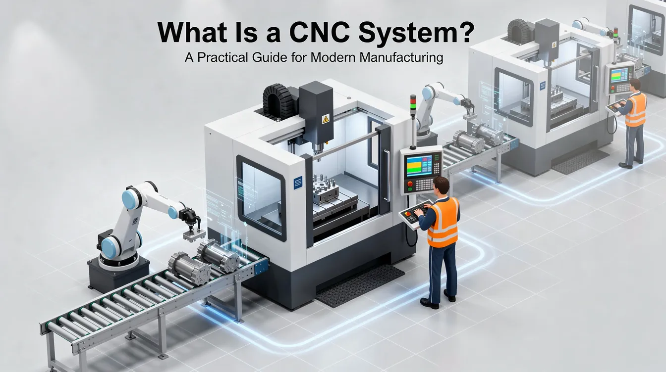
What Is a CNC System? A Practical Guide for Modern Manufacturing
If you’ve ever sourced precision parts or worked with a contract manufacturer, you’ve likely encountered the term “CNC system.” But what exactly does it include, and why does it matter for the parts you receive? This guide breaks down the full CNC system – from controller hardware to software workflow – so engineers and purchasing teams can make better-informed decisions when specifying and sourcing machined components.
What Is a CNC System? (Quick Answer for Busy Engineers)
A CNC system is an automated manufacturing setup directing production machinery movement through digital instructions rather than manual control. It is the complete combination of hardware and software that controls cnc machines – including cnc mills, cnc lathes, cnc routers, cnc plasma cutting tables, cnc laser cutters, and more.
In cnc manufacturing, the “system” is far more than the physical machine sitting on the shop floor. It encompasses:
-
The cnc controller (machine control unit)
-
Motor drives and servo motors or stepper motors
-
Feedback devices such as encoders and linear encoders
-
The human-machine interface (HMI)
-
The upstream link to cad software and cam software
This distinction matters. A cnc machine refers to the physical machine tool – the spindle, the bed, the axes. A cnc system refers to the control architecture, software, and machine acting together as one integrated unit. CNC machining uses pre-programmed software to control machinery, meaning the system’s intelligence lives in the digital layer just as much as in the mechanical one.
At Anebon Metal Products Limited, we use advanced multi-axis cnc systems daily to produce OEM parts serving the automotive industry, aerospace, medical device manufacturing, and the electronics industry. Understanding what makes up a cnc system helps our clients specify requirements more effectively and evaluate manufacturing partners with greater confidence.
What Does CNC Stand For and How Do CNC Systems Work?
Understanding the acronym is the starting point for understanding the entire cnc machining process and why cnc technology has reshaped the manufacturing industry.
CNC stands for Computer Numerical Control. The term numerical control refers to tool motion defined by numeric code – specifically g code (geometric code for motion commands) and M-codes that control machine functions unrelated to positioning, such as coolant activation and spindle start/stop. Early numerical control systems in the 1940s and 1950s used punched tape; the shift to digital computers and microprocessors in the 1960s–70s gave birth to computer numerical control cnc as we know it today.
The Basic Workflow
The cnc manufacturing process transforms raw materials into finished parts through four main stages:
-
CAD modeling – A design engineer creates a 2D drawing or 3D solid model using computer aided design cad software. Common file formats include .STEP, .IGES, .DWG, and .DXF.
-
CAM programming – Computer aided manufacturing cam software converts the CAD model into toolpaths. The cnc machinist or programmer selects cutting tool types, machining strategies (roughing, finishing), feed rates, and spindle speeds. The aided manufacturing cam software then generates the g code file and simulates the operation to catch collisions before metal is cut.
-
Program transfer – The computer program is sent to the cnc controller via USB, Ethernet, or DNC (direct numerical control) link.
-
Execution – The controller parses the g code, performs interpolation (linear, circular, spline), and coordinates motion across the x axis, Y, and Z linear axes – plus rotary axes A, B, and C on multi-axis machine tools.
CNC systems operate using a Cartesian coordinate system, and cnc machines can control multiple axes, typically X, Y, and Z. CNC programming uses g code to control machine movements, and cnc programming allows for precise control of tool speed and feed rate. This means cnc programming can automate complex machining tasks that would be impractical or impossible under manual control.
Modern cnc systems store programs in memory, allow real-time edits via MDI (manual data input), and can run lights-out production with minimal cnc operator intervention – enabling faster production and significantly higher throughput than manual labor alone.
Main Components of a CNC System
A cnc system is a tightly integrated set of mechanical, electrical, and software components. Each element plays a specific role, and weakness in any single component limits the whole system’s capability. CNC systems commonly include components such as program input devices, machine control units, and drive systems.
CNC Controller (Machine Control Unit) – The controller is the “brain” of the system. A Machine Control Unit interprets g code and generates electrical signals for machine operations. It calculates toolpaths, manages interpolation across all axes simultaneously, and handles path look-ahead to smooth rapid direction changes. Modern controllers use microprocessors or DSP/FPGA units running real-time operating systems, with look-ahead buffers that can pre-process hundreds or thousands of code blocks. For a deeper look at controller architecture in milling applications, see our guide on what are the main components of CNC milling machine.
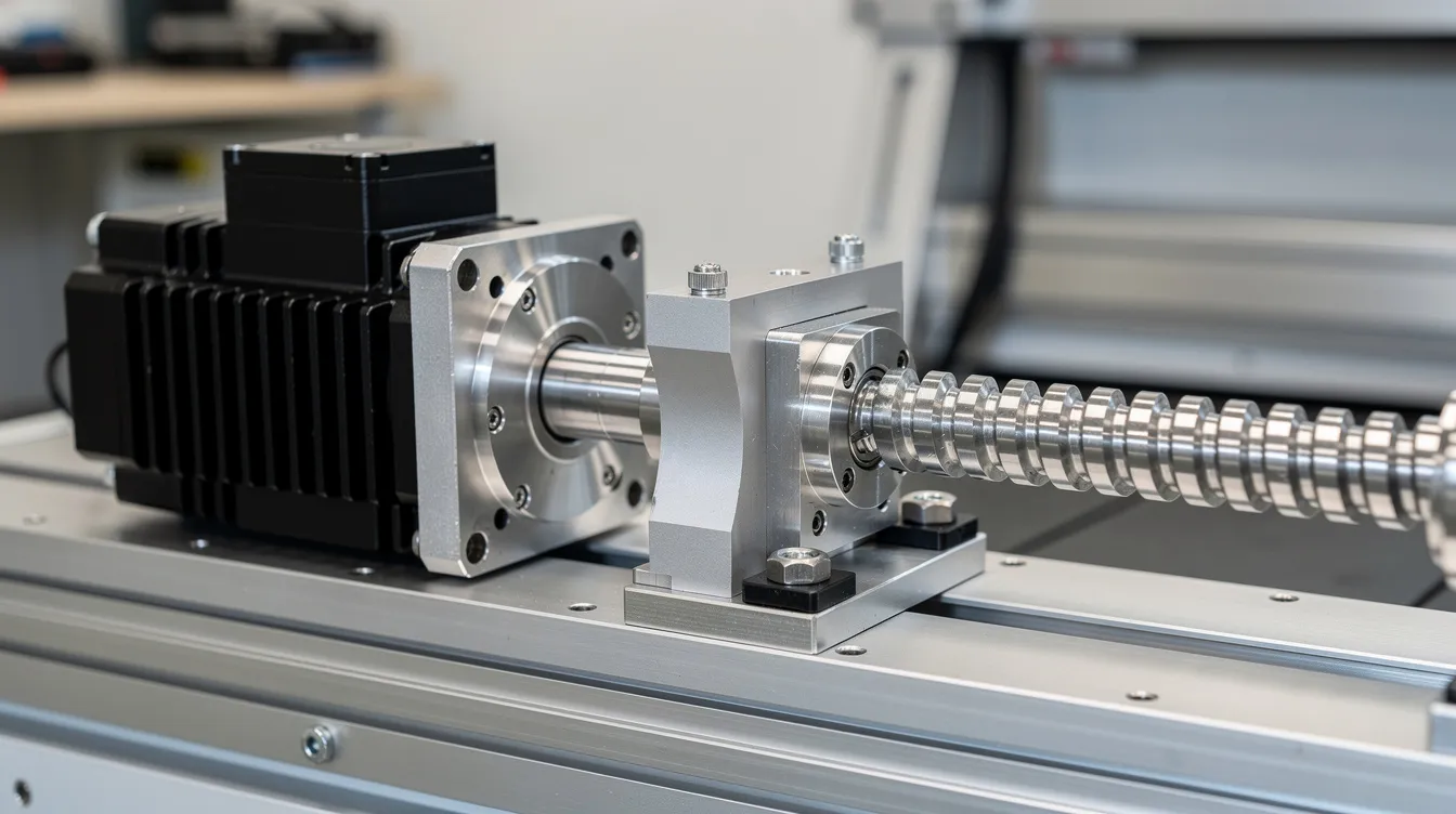
Motors and Drives – A cnc machine uses a drive system consisting of motors and mechanisms for precise movement. Two main motor types dominate:
|
Feature |
Stepper Motors |
Servo Motors |
|---|---|---|
|
Control loop |
Open-loop (typically) |
Closed-loop |
|
Torque at speed |
Drops off at higher RPM |
Maintained across speed range |
|
Feedback |
None (unless hybrid) |
Encoder or resolver |
|
Cost per axis |
Lower (baseline) |
|
|
Best for |
Hobby/light-duty cnc routers |
Industrial cnc machine tools |
Stepper motors move in discrete steps (e.g., 1.8° per step) and work well for lighter, open-loop systems. Servo motors with closed-loop drives deliver high dynamic response, maintain torque at speed, and are the standard for high precision industrial cnc machinery.
Feedback and Positioning Systems – Feedback systems in cnc machines provide real-time data about the tool’s actual position and speed. Closed-loop systems use incremental or absolute encoders (10,000 to 1,000,000 counts per revolution) and linear encoders with sub-micron resolution. This data feeds back to the controller, which corrects positional errors in real time – critical for holding tight tolerances.
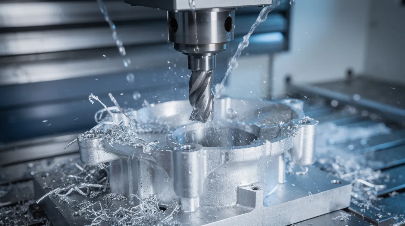
Machine Tool Structure – The mechanical platform – whether a cnc milling machine, cnc lathe, machining center, cnc router, or cnc plasma cutting table – provides the bed, column, spindle housing, linear guides, and ball screws that physically move the cutting tool and workpiece. Machine stiffness, thermal stability, and backlash directly limit achievable accuracy.
Spindle System – The spindle motor rotates the cutting tool (in milling) or the rotating workpiece (in turning). General machining centers run spindles at 12,000–18,000 RPM; high-speed machines for fine detail or plastics reach 30,000 RPM or higher. Torque, balance, and run-out all affect workpiece surface finish.
Tooling and Workholding – End mills, drills, inserts, boring bars, and taps are held in precision tool holders (CAT, BT, HSK tapers). Workholding – vises, chucks, fixture plates, vacuum tables – secures the part and defines datum accuracy. Even the best controller and servo motors cannot overcome poor fixturing.
At Anebon, our high-end servo-driven, closed-loop cnc systems with precision ball screws and linear guides achieve tolerances down to ±0.002 mm, meeting the demands of aerospace, medical, and automotive sectors.
CNC System Architecture: From CAD/CAM to Cutting
CNC systems follow a digital thread from design to finished part. Every step in this chain – from a sketch on an engineer’s screen to chips flying off the workpiece – is governed by the system’s architecture.
CAD – Computer Aided Design – CAD design involves creating a digital blueprint using computer aided design software. Engineers model the part geometry in 2D or 3D, defining dimensions, tolerances, surface finishes, and material callouts. Typical file formats supplied by OEM clients include .STEP, .IGES, .SLDPRT (SolidWorks), and .CATIA. The quality of the CAD model directly affects every downstream step.
CAM – Computer Aided Manufacturing – Computer aided manufacturing software converts the CAD model into executable toolpaths. The cnc machinist selects machining processes (roughing, semi-finishing, finishing), defines tool engagement strategies, and specifies feeds and speeds. The software programs then simulate the entire cnc machining process virtually – checking for collisions, gouges, and inefficient moves – before generating the final g code. CNC systems often utilize CAD and CAM software for programming, forming a seamless digital pipeline.
Program Transfer and Execution – The CNC program transfers to the machine via network, USB, or DNC link. The cnc controller loads the code, and execution begins. In open-loop systems (common on hobby cnc routers), the controller sends step commands without verifying actual position – acceptable for lower-precision work. In closed-loop systems used on industrial cnc mills and cnc turning centers, encoders continuously confirm position, enabling the controller to correct deviations in real time.
At Anebon, our engineering team collaborates with OEM clients at the CAD/CAM stage, providing DFM (Design for Manufacturability) feedback before cnc programming begins. Industry benchmarks show that early DFM involvement can reduce manufacturing cost by 10–30% and compress lead times by optimizing features for machinability.
Types of CNC Machines Within a CNC System
A “cnc system” is an umbrella that controls many kinds of cnc machines, each optimized for specific tasks and materials. The choice of machine type depends on part geometry, material, tolerance, and production volume.
CNC Milling and CNC Mills
CNC mills typically operate on a three-axis system (X, Y, Z), suitable for flat surfaces, pockets, holes, and simple contours. Vertical and horizontal machining centers expand capability with automatic tool changers, pallet systems, and high-speed spindles. For complex geometries – such as turbine blades, impellers, and mold cavities – 5-axis CNC machining enables simultaneous control of three linear and two rotary axes. This eliminates multiple setups, improves accuracy, and reduces cycle time. To understand how cnc milling machine works in practice, the interaction between spindle, cutting tool, and workpiece across multiple axes is key.
CNC Turning and CNC Lathes
CNC lathes are used for producing circular designs – shafts, bushings, housings, threaded fittings, and high-volume automotive industry components. Basic cnc turning machines operate on two axes (X and Z), with the rotating workpiece spinning against a stationary or live cutting tool. Multi-axis turning centers add live tooling, Y-axis, and B-axis capability, enabling milling operations without a second setup. Swiss-type cnc lathes handle very small, slender parts with extreme precision.
CNC Plasma Cutting and CNC Laser
CNC plasma cutting uses plasma cutters that employ a plasma torch to cut materials – typically steel, aluminum, and stainless steel plate. Cnc laser systems offer finer kerf widths and tighter tolerances for sheet metal fabrication. Both are controlled by the same fundamental cnc architecture: controller, drives, motors, and g code.
Specialty CNC Machines
-
EDM (Electrical Discharge Machining) – Electric discharge machines mold workpieces using electrical sparks. Wire edm cuts intricate profiles using a thin electrically charged wire, while sinker edm uses a shaped electrode to form cavities. The electrical arc erodes material without mechanical force, making EDM ideal for hardened steels and complex machinery components. This process is sometimes called spark machining.
-
CNC Routers – Optimized for wood, plastics, composites, and soft metals, cnc routers use high-speed spindles and large work envelopes.
-
Waterjet – Water jet cutters use high-pressure water (often with abrasive garnet) to cut hard materials without heat-affected zones – important for heat-sensitive alloys and composites.
Anebon focuses on precision cnc machining (milling, turning, 5-axis), die casting post-machining, and sheet metal fabrication – rather than selling cnc machines themselves. Our role is applying these modern machines and cnc tools to produce your parts.
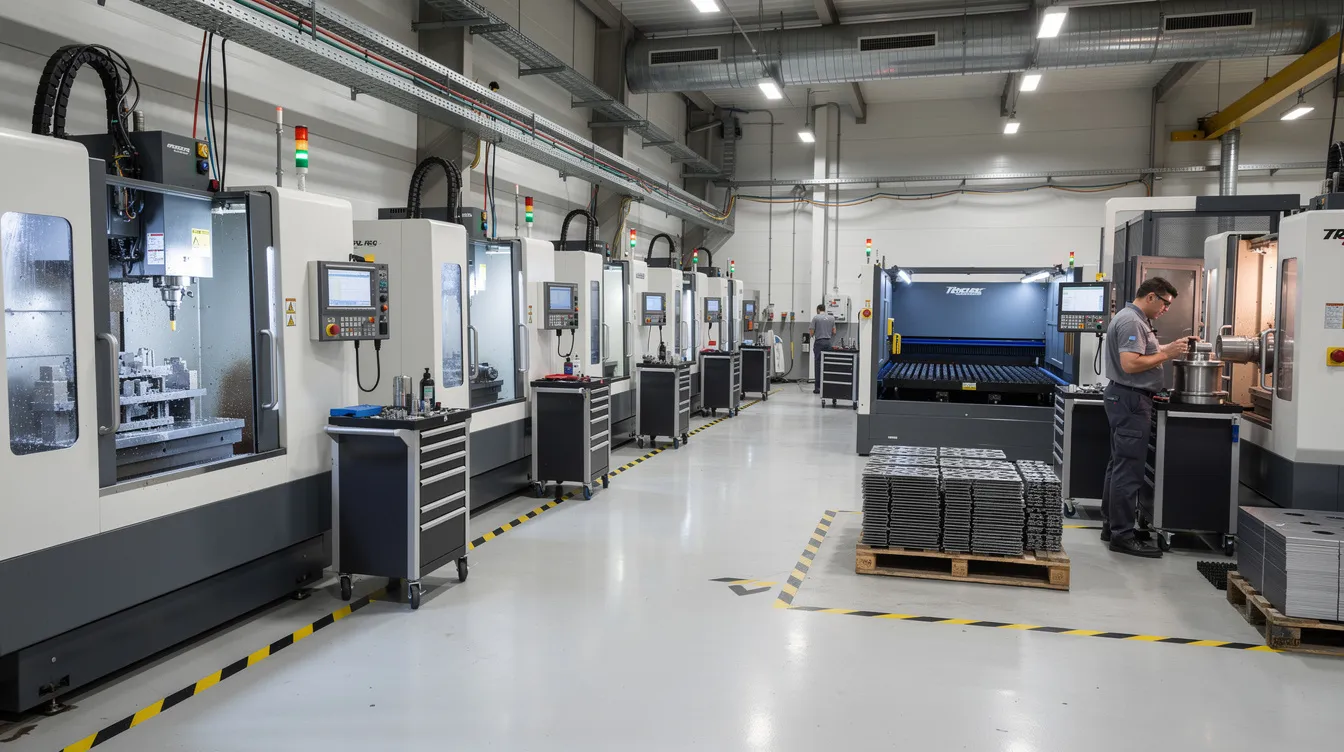
How CNC Systems Are Used in Key Industries
CNC systems underpin high precision production across virtually every manufacturing sector worldwide. CNC manufacturing excels in creating complex, high-tolerance industrial components across multiple industries. Here is where cnc technology delivers the most impact.
Automotive – The automotive industry uses CNC for engine components and body panels, as well as transmission cases, brackets, molds, and custom fixtures. Repeatability across tens of thousands of parts makes cnc systems essential for mass production in automotive sectors. Cnc machining makes it possible to hold dimensional consistency part after part across an entire production line.
Aerospace – CNC machining is extensively used in the aerospace industry. Structural ribs, turbine blades, landing gear components, and lightweight aluminum and titanium parts with complex 5-axis profiles all rely on multi-axis cnc systems. Tolerances in aerospace are among the tightest in any manufacturing process, and traceability requirements demand full data logging.
Medical – CNC machines create parts for the medical industry, including implants, surgical instruments, and housings for diagnostic electronic devices. Medical device manufacturing demands biocompatible materials (titanium, surgical stainless steel, PEEK) machined to micron-level precision. CNC machining makes these parts repeatable and traceable under regulatory frameworks.
Electronics and Robotics – CNC technology is vital for producing electronic components like PCBs, heatsinks, RF enclosures, connectors, and custom robotic frames. The electronics industry requires fine surface finishes and tight tolerances on aluminum and engineering plastics, often in moderate volumes with rapid iteration cycles.
Oil and Gas – CNC machining is used in the oil and gas industry for precise parts such as valve bodies, couplings, drill components, and downhole tools. These parts must withstand extreme pressures and temperatures, requiring robust materials and high precision machining processes.
Anebon serves overseas OEMs across all of these sectors, applying the right combination of cnc tools, materials, and quality systems to meet each industry’s specific requirements.
Benefits of Modern CNC Systems for OEM Manufacturing
CNC systems form the backbone of efficient, scalable cnc manufacturing, and their advantages compound as production volumes and part complexity increase.
Precision and Repeatability – CNC machining achieves high precision with tight tolerances, often ±0.005 mm in standard work and ±0.002 mm at the high end. Once a cnc program is proven, every subsequent part replicates the same dimensions – critical for machine parts that must interchange across assemblies.
Reduced Human Error – CNC systems reduce human error in manufacturing processes by replacing manual control with an automated manufacturing process governed by verified computer code. Unlike manual labor, the system doesn’t fatigue, lose focus, or introduce variation from shift to shift.
Autonomous, Continuous Operation – CNC technology operates autonomously once programmed, eliminating manual intervention. CNC machines can run continuously without breaks, enabling 24/7 lights-out shifts that dramatically improve throughput and reduce cost per part. CNC technology improves production rates significantly compared to conventional methods.
Complex Geometry Capability – CNC technology allows for complex geometries in parts production – undercuts, freeform surfaces, deep pockets, and multi-face features that would be impractical or impossible by hand. Modern manufacturing increasingly demands these geometries for performance-optimized designs.
Flexibility and Speed – Quick program changeovers support rapid prototyping, engineering changes, and small-batch customization for R&D teams. The same cnc machine tools can switch from one part number to another in minutes, enabling faster production across mixed product lines. This flexibility serves the entire manufacturing sector, from one-off prototypes to scaled production.
Quality and Traceability – Modern cnc systems integrate in-process probing, data logging of spindle load and temperature, and direct links to quality management systems. Certifications such as ISO 9001:2015 require documented process control and traceability – capabilities built into today’s cnc systems. Even adjacent processes like injection molding benefit from CNC-machined molds held to tight tolerances.
Anebon leverages all of these cnc system benefits to deliver tight tolerances, broad material options (aluminum, stainless steel, titanium, engineering plastics), and reliable lead times for overseas clients across multiple functions and industries.
Anebon’s CNC System Capabilities and How to Get Started
Anebon Metal Products Limited is a precision cnc machining and fabrication partner – not an equipment vendor. We apply advanced cnc systems to transform your designs into finished, inspected parts ready for assembly.
Our capabilities include:
-
Multi-axis CNC milling (3-axis through full 5-axis machining)
-
CNC turning and multi-axis turning centers
-
Die casting post-machining
-
Sheet metal fabrication (laser cutting, bending, welding)
-
Tolerances as tight as ±0.002 mm on critical features
-
Materials including aluminum alloys, stainless steel, titanium, brass, copper, and engineering plastics
Founded in 2010 in Dongguan, Guangdong, China, Anebon holds ISO 9001:2015 and ISO 14001:2015 certifications. These credentials are not just badges – they represent documented process control, environmental responsibility, and the traceability that overseas OEMs require for aerospace, medical, and automotive supply chains.
Typical Engagement Flow
-
RFQ submission – You send CAD files (STEP, IGES, or native format) along with drawings, material specs, and quantity requirements.
-
DFM review – Our engineering team reviews your design for manufacturability, flagging potential issues and suggesting optimizations to reduce cost and lead time.
-
Process planning and cnc programming – We select the optimal machining processes, cnc tools, fixturing strategy, and program the cnc systems.
-
Sample / prototype – First articles are produced, inspected, and shipped for your approval.
-
Scaled cnc manufacturing – Upon approval, we ramp to your required volumes with consistent quality and on-time delivery.
Whether you need a single prototype or a full production run, understanding what sits behind the cnc system helps you evaluate manufacturing partners with confidence.
A well-designed cnc system plus an experienced manufacturing partner is the foundation of reliable, high precision OEM parts. If you’re ready to move forward, request a quote or share your CAD files with Anebon’s engineering team to start your next cnc machining, cnc milling, or cnc system-based production project.