Unraveling the Calculations: The Link between Cutting Speed and Feed Speed
What do you think is the relationship between cutting speed, tool engagement, and feed speed in CNC machining?
For optimal performance, it is important to understand the relationship between feed speed, cutting speed and tool engagement in CNC machining.
Cutting Speed:
The cutting speed is the rate of rotation or movement through the material. The speed is usually measured in surface feet per minutes (SFM) or meters/minute (m/min). Cutting speed is determined by material to be machined, the cutting tool, and desired surface finish.
Tool Engagement
The tool engagement is the depth to which a cutting tool penetrates a workpiece during machining. The tool engagement is affected by factors such as cutting tool geometry and feeds and speeds as well as desired surface quality and material removal rate. By selecting the appropriate tool size, depth of cut and radial engagements, you can adjust tool engagement.
Feed Speed
The feed speed is also called feed rate or the feed per tooth. It is the rate that the cutting tool advances per revolution through the material of the workpiece. The speed is measured in millimeters or inches per minute. The feed rate directly affects tool life, surface quality, and overall machining performance.
In general, higher cutting speeds result in greater material removal rates. However, they also produce more heat. The cutting tool’s ability to handle higher speeds, and the coolant’s efficiency in dissipating the heat are important factors.
The tool engagement should be adjusted according to the material properties of the workpiece, the geometry of the cutting tools, and the desired finish. Proper tool engagement will ensure effective chip evacuation and minimize tool deflection. It will also improve cutting performance.
The feed speed should be chosen to achieve the desired rate of material removal and finish, without overloading the tool. A high feed rate can cause excessive tool wear. However, a low feed speed will result in poor surface finish and inefficient machining.
The programmer must write the instructions into the CNC program to determine the amount of cutting for each process. Cutting speed, back-cutting amount, feed speed and so on are all part of cutting usage. Different cutting amounts are required for different processing methods.
1. Selection principle of cutting amount
When roughing, the main focus is generally on improving productivity, but economy and processing costs should also be considered; when semi-finishing and finishing, cutting efficiency, economy, and processing costs should be taken into consideration while ensuring processing quality. The specific values should be determined according to the machine tool manual, cutting usage manual, and experience.
Starting from the durability of the tool, the order of selection of cutting amount is: first determine the amount of back cutting, then determine the feed amount, and finally determine the cutting speed.
2. Determination of the amount of knife on the back
The amount of back cutting is determined by the stiffness of the machine tool, workpiece and tool. If the stiffness allows, the amount of back cutting should be equal to the machining allowance of the workpiece as much as possible. This can reduce the number of tool passes and improve production efficiency.
Principles for determining the amount of knife on the back:
1)
When the surface roughness value of the workpiece is required to be Ra12.5μm~25μm, if the machining allowance of CNC machining is less than 5mm~6mm, one feed of rough machining can meet the requirements. However, when the margin is large, the rigidity of the process system is poor, or the power of the machine tool is insufficient, it can be completed in multiple feeds.
2)
When the surface roughness value of the workpiece is required to be Ra3.2μm~12.5μm, it can be divided into two steps: roughing and semi-finishing. The back cutting amount selection during rough machining is the same as before. Leave a margin of 0.5mm to 1.0mm after rough machining and remove it during semi-finishing.
3)
When the surface roughness value of the workpiece is required to be Ra0.8μm~3.2μm, it can be divided into three steps: roughing, semi-finishing and finishing. The back cutting amount during semi-finishing is 1.5mm~2mm. During finishing, the back cutting amount should be 0.3mm~0.5mm.
3. Calculation of the feed amount
The amount of feed is determined by the accuracy of the part and the surface roughness required, as well as on the materials selected for the tool and the workpiece. The maximum feed rate depends on the rigidity of the machine and the performance level of the feed system.
Principles for determining feed speed:
1) If the workpiece quality can be assured, and you want to increase production efficiency, then a faster feed speed is recommended. In general, the feed speed is set between 100m/min and 200m/min.
2) If you are cutting or processing deep holes, or using high-speed steels, it is best to use a slower feed speed. This should be between 20 and 50m/min.
When the requirement for accuracy in machining and roughness of the surface is high, it is best to select a smaller feed speed, usually between 20m/min and 50m/min.
You can choose the maximum feed rate set by the CNC machine tool system when the tool is idle, and especially “returning zero” over a distance.
4. Spindle speed determination
The spindle should be chosen based on the maximum cutting speed allowed and the diameter of your workpiece or tool. The calculation formula for spindle speed is:
n=1000v/pD
The durability of the tool determines the speed.
Spindle speed is measured in r/min.
D —- Workpiece diameter or tool size, measured in mm.
The final spindle speed is calculated by choosing a speed the machine tool can achieve or comes close to, according to its manual.
Shortly, the value of the cutting amount can be calculated by analogy, based on machine performance, manuals, and real-life experience. Spindle speed and cutting depth can be adjusted to the feed speed to create the optimal amount of cutting.
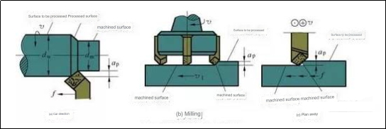
1) Back cutting amount (cutting depth) ap
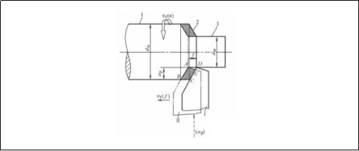
Back cutting amount is the vertical distance between the surface to machine and the surface that has been machined. Back cutting is the amount of cutting measured perpendicularly to the plane of work through the base point. The cutting depth is the amount of cutting that the turning tool makes into the workpiece with each feed. The amount of cutting at the back of the outer circle can be calculated using the formula below:
a p = ( d w — d m ) /2
In the formula, a p——the amount of knife on the back (mm);
dw——The diameter of the surface to be processed of the workpiece (mm);
dm – machined surface diameter of the workpiece (mm).
Example 1: It is known that the surface diameter of the workpiece to be processed is Φ95mm; now the diameter is Φ90mm in one feed, and the amount of back cutting is found.
Solution: a p = (d w — d m) /2= (95 —90) /2=2.5mm
2) Feed amount f
The relative displacement of the tool and the workpiece in the direction of feed motion for each revolution of the workpiece or tool.
According to the different feeding directions, it is divided into longitudinal feed amount and transverse feed amount. The longitudinal feed amount refers to the feed amount along the direction of the lathe bed guide rail, and the transverse feed amount refers to the direction perpendicular to the lathe bed guide rail. Feed rate.
Note: The feed speed v f refers to the instantaneous speed of the selected point on the cutting edge relative to the feed movement of the workpiece.
v f=fn
where v f——feed speed (mm/s);
n——Spindle speed (r/s);
f——feed amount (mm/s).
3) Cutting speed v c
Instantaneous velocity in the main motion at a specific point on the cutting blade relative to the workpiece. Calculated by :
vc=(pdwn)/1000
Where v c —-cutting speeds (m/s);
dw = diameter of the surface to be treated (mm);
—- Rotation speed of the workpiece (r/min).
Calculations should be made based on maximum cutting speeds. Calculations should, for example, be made based on the diameter and wear rate of the surface being machined.
Find vc. Example 2: When turning the outer circle of an object with a diameter Ph60mm on a lathe, the spindle speed selected is 600r/min.
Solution: v c=( p d w n )/1000 = 3.14x60x600/1000 = 113 m/min
In real production, it is common to know the diameter of the piece. Cutting speed is determined by factors like the material of the workpiece, tool material and processing requirements. To adjust the lathe, the cutting speed is converted to the spindle speed of the lathe. This formula can be obtained:
n=(1000vc)/pdw
Example 3: Select vc to 90m/min and find n.
Solution: n=(1000v c)/ p d w=(1000×90)/ (3.14×260) =110r/min
After calculating lathe spindle speeds, select a value that is close to the numberplate, for example, n=100r/min as the lathe’s actual speed.
3. Summary:
Cutting amount
1. Back knife amount ap (mm) ap= (dw – dm) / 2 (mm)
2. Feeding amount f (mm/r)
3. Cutting speed vc (m/min). Vc=dn/1000 (m/min).
n=1000vc/d(r/min)
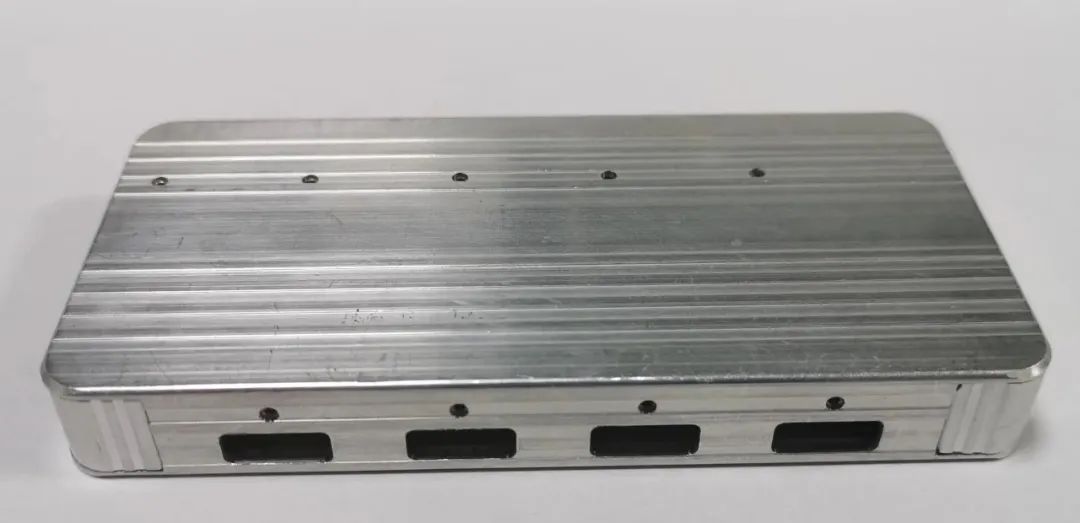
As far as our common CNC aluminum parts are concerned, what are the methods to reduce the processing deformation of aluminum parts?
Proper Fixturing:
Fixturing the workpiece correctly is crucial to minimizing distortion during machining. By ensuring that the workpieces are securely clamped in place, vibrations and movements can be reduced.
Adaptive Machining
Sensor feedback is used to adjust the cutting parameters dynamically. This compensates for material variations, and minimizes deformation.
Cutting Parameters Optimization
Deformation can be minimized by optimizing parameters like cutting speed, feedrate, and depth cut. By reducing cutting forces and heat production by using the appropriate cutting parameters, distortion can be minimized.
Minimizing Heat Generation:
The heat generated during machining may lead to thermal deformation and expansion. To minimize heat production, use coolant or lubricants. Reduce cutting speeds. Use high-efficiency tool coats.
Gradual Machining
It is better to make multiple passes when machining aluminum than one heavy cut. Gradual machining minimizes deformation by reducing the heat and cutting forces.
Preheating:
Preheating aluminum before machining may reduce the risk of distortion in certain situations. Preheating stabilizes the material and makes it more resistant to distortion when machining.
Stress Relief Annealing
Stress relief annealing can be performed after machining to reduce residual stresses. The part can be stabilized by heating it to a certain temperature, then cooling it slowly.
Selecting the Right Tooling
In order to minimize deformation, it is important to select the right cutting tools, with the appropriate coatings and geometries. Specially designed tools for aluminum machining reduce cutting forces, improve surface finish, and prevent the formation of built-up edges.
Machining in stages:
Multiple machining operations or stages can be used to distribute cutting forces on complex cnc aluminum parts and reduce deformation. This method prevents localized stresses and reduces distortion.
Anebon pursuit and company purpose is always to “Always satisfy our consumer requirements”. Anebon keep on to acquire and style and design remarkable high-quality products for each our outdated and new customers and reach a win-win prospect for Anebon’s consumers as well as us for Original Factory Profile extrusions aluminum, cnc turned part, cnc milling nylon. We sincerely welcome friends to barter business enterprise and start cooperation with us. Anebon hope to hitch hands with close friends in different industries to produce a brilliant long run.
China Manufacturer for China High Precision and Metal Stainless Steel Foundry, Anebon is seeking the chances to meet all the friends from both at home and abroad for the win-win cooperation. Anebon sincerely hope to have long-term cooperation with all of you on the bases of mutual benefit and common development.
If you want to know more, please contact the Anebon team at info@anebon.com.


