Understanding Thread Depth: Key Insights for Accurate Measurement
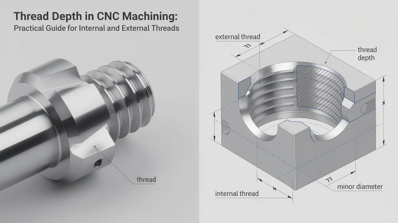
Thread Depth in CNC Machining: Practical Guide for Internal and External Threads
Thread depth determines whether a fastened joint holds or fails. For engineers specifying threaded features on OEM parts, understanding how deep a thread must go – and why – is the difference between a reliable assembly and a warranty claim. This guide covers everything from definitions and material-dependent engagement rules to measurement methods, CNC programming, and common mistakes.
Quick Answers: What Is Thread Depth and Why It Matters
Thread depth is the axial distance from the first full-formed thread to the last full-formed thread along the hole or boss axis. It is not the same as thread height (the crest-to-root distance perpendicular to the axis).
Why thread depth is critical for OEM parts:
-
Proper thread depth allows load to be distributed evenly across multiple engaged threads, preventing localized overload.
-
Insufficient engagement causes fastener failure under load as the threads may shear or snap.
-
A secure, deep enough fit ensures that the stress is evenly distributed across multiple threads, preventing stripping in applications like M10x1.5 wheel hub bolts or titanium bone screws.
-
Correct depth supports clamp force, leak-tight seals, and fatigue resistance across automotive, medical, aerospace, and electronics assemblies.
Anebon Metal Products Limited routinely machines internal thread and external thread features with controlled depths from prototype through series production, certified to ISO 9001:2015.
Relevant standards for depth decisions include ISO 965 for metric threads, ASME B1.1 for UNC/UNF, and application-specific specifications in aerospace and medical sectors.
Thread Depth vs. Thread Height (hs / hn)
These two terms appear on drawings constantly – and confusing them causes trouble.
-
Thread height is the distance from the crest to the root, measured normal to the axis. ISO notation uses hs for external threads and hn for internal threads. For the standard 60° v shape profile, the theoretical height H ≈ 0.8660 × pitch, while the functional height after truncation is approximately 0.54125 × pitch.
-
Thread depth refers to the vertical distance between the crest and the root of a screw thread in a geometric sense, but in practice engineers use it to mean the axial length of usable engagement along the hole or shank.
-
The formula for thread height is: hn = hs = (major diameter − minor diameter) / 2 ≈ 0.54125 × P.
-
Most hardware features a 60° thread angle with a calculated thread depth that accounts for flat crests and rounded roots – the full theoretical v shape is never fully present.
-
Thread depth is also described as the distance the thread extends from the minor diameter to the major diameter of a screw.
Design engineers should specify axial thread depth on drawings when functional engagement is critical, and never rely on height alone.
Designing Internal Threads: Depth, Materials, and Standards
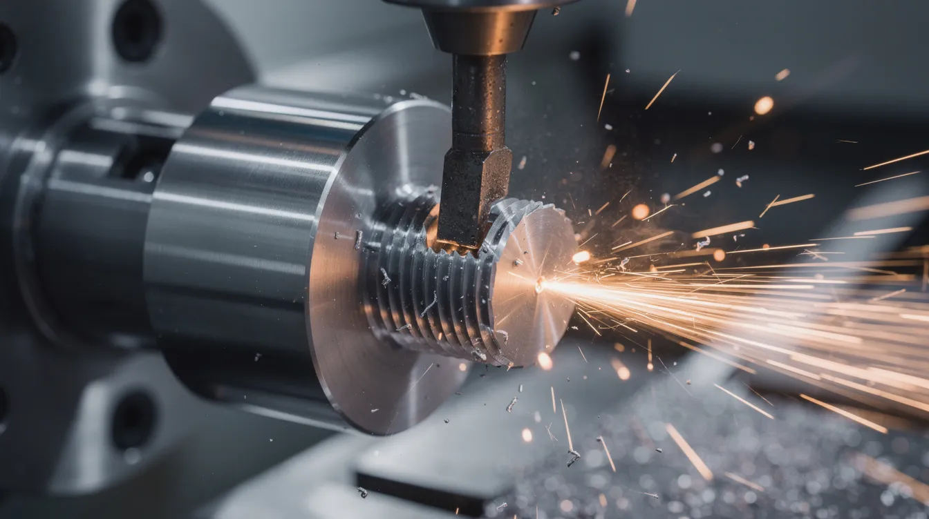
Internal threads are female forms in tapped or milled holes – common in housings, brackets, and enclosures. Getting the minimum thread depth right depends on material, load, and whether the hole is blind or through.
-
Deeper threads increase the shear area of the engaged material, directly raising pull-out strength.
-
In steel, engagement of 1.0–1.5 × nominal diameter is typically sufficient: a 1 2 13 UNC hole in medium-carbon steel needs roughly 0.625–0.75 inch effective depth.
-
Soft materials need deeper threads to prevent stripping. For aluminum 6061 or die-cast zinc, use 1.5–2.0 × diameter. Deeper threads provide a better bite into softer materials like wood or plastic.
-
Example: M4×0.7 in steel requires 6–8 mm min full depth for small electronics screws; M10×1.5 in a structural aluminum joint may need 20–25 mm.
-
Usable thread depth indicates the distance of the last full-formed thread, which is critical for calculating engagement strength.
-
Fastener standards are engineered with a specific depth profile to develop full tensile strength in the bolt before the internal thread strips.
-
In blind holes, allow 1–1.5 × pitch unthreaded clearance at the bottom to avoid tap bottoming.
-
Internal thread classes (2B/3B for UNC, ISO 6H for metric) affect tolerance for depth-related burrs. Thread Class 1B, 2B, 3B are for internal threads.
-
Recommend calling out “M8×1.25 – 16 mm MIN FULL THREAD” on drawings rather than vague notes.
Designing External Threads: Length, Boss Diameter, and Chamfers
External threads are male forms on shafts, studs, and fasteners. Here, “thread depth” is discussed as threaded length along the shank.
-
Thread Class 1A, 2A, 3A are for external threads, with 2A being the most common for general-purpose bolt and stud applications.
-
If threads are cut too deeply, the crests and roots become too thin, weakening the fastener and risking fracture at the root.
-
Lead-in chamfers consume 1–2 pitches at each end where threads are incomplete – do not count these toward full engagement.
-
Boss diameter and undercuts on turned parts influence usable length. A 1″-12 UNF external thread with a relief groove near the shoulder may lose 3–5 mm of engagement.
-
Shallower threads have more surface contact area, reducing the likelihood of loosening under vibration – relevant for fine-pitch external threads in automotive and aerospace.
-
Specify “usable thread length” on drawings (e.g., “3/8-16 UNC, 18 mm MIN FULL THREAD”) and allow extra run-out for manufacturing tolerance. Surface finish targets (Ra) and class also affect mating depth and torque behavior.
Standard Thread Dimensions and the Case of 1/2 – 13 UNC
Basic dimensions – major diameter, minor diameter, pitch diameter, and theoretical height – come from standards tables like ASME B1.1.
-
The 1 2 13 UNC thread has 13 threads per inch (tpi), giving a thread pitch of approximately 0.0769 inch. The theoretical thread height ≈ 0.54125 × 0.0769 ≈ 0.0416 in.
-
1/2 – 13 UNC has three external thread classes (1A, 2A, 3A) and three internal thread classes (1B, 2B, 3B). Tighter classes require closer control of depth-related burrs and chamfers.
-
Permissible values are calculated for a length of engagement of 5×Pitch, which for this size equals about 0.385 in.
-
For full-strength joints in medium-carbon steel, 0.625–0.750 in internal thread depth is typically recommended – enough engagement for the bolt to reach full tensile capacity before the threads strip.
-
CNC calculators and thread calculation formula references help machinists select tap drill size, oversize allowances, and safe maximum thread depth for 1 2 13 and comparable UNC sizes like 1 4 20 and 8 32.
Metric Threads: Depth Guidelines and Common Sizes
ISO metric threads use the designation format M[diameter]×[pitch] – e.g., M6×1, M12×1.75. The thread pitch directly determines cutting depth and height.
-
Coarse threads typically have a greater thread depth compared to fine threads. For example, M10×1.5 (coarse) has a greater per-thread height than M10×1.25 (fine), meaning coarse vs fine selection affects engagement calculations.
-
Hard materials require shallower threads to avoid stripping and allow for precise alignment. Shallow threads provide less bite but retain a larger root diameter, making them better for hard materials like hardened steel or brass.
-
Common ranges: M4×0.7 in steel needs 6–8 mm depth; M10×1.5 needs 15–18 mm; M12×1.75 needs 18–24 mm. These increase by 50–100% in aluminum or softer alloys.
-
Anebon handles metric threads in CNC machining and die casting, accounting for casting draft and machining stock to achieve final depth and accurate dimensions.
-
Switching between inch (like 1 4 or 3 4 size) and metric threads on the same part requires re-evaluating engagement depth – do not copy values directly between systems.
Measuring and Verifying Thread Depth on the Shop Floor
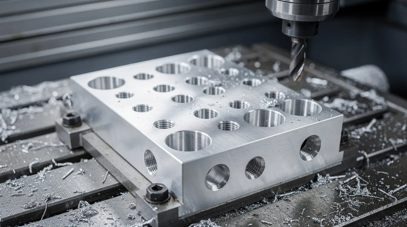
Accurate verification prevents rejected parts and field failures.
-
Common tools include go/no-go plug gage sets for internal threads, ring gauges for external threads, and dedicated thread depth instruments.
-
For measuring usable thread depth in a hole, thread a bolt in fully and measure the protruding length – the difference between bolt length and protrusion gives engagement distance.
-
Counting turns works for coarse QC: for 1 2 13, 13 turns ≈ 1 in axial distance. Quick, but insufficient for ±0.1 mm tolerances.
-
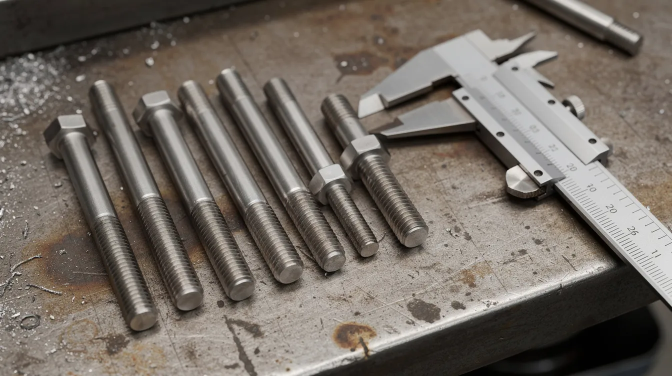
Digital and analog thread depth gauges are commonly used. Operators often prefer durable analog thread depth gauges for shop-floor reliability, while a sliding gage can provide accurate depth measurements in production. Calipers can measure thread depth by zeroing on the bolt crest.
-
For critical aerospace or medical threads, advanced measurement tools like CMM scanning probes or X-ray CT provide full profile and depth mapping.
-
Specify realistic tolerances (e.g., ±0.25 mm) and inspection plans on drawings so that QC can match customer specifications.
Thread Milling vs Tapping: Impact on Achievable Thread Depth
The process you choose directly affects how reliably you can hit a target depth.
-
Tapping (rigid or floating) is fast and cost-effective for production but offers limited flexibility for non-standard depths. In blind holes, taps risk bottoming if clearance is insufficient.
-
Thread milling uses a cutter on a CNC milling machine to interpolate the thread profile. It allows precise depth control, programmable chamfers, and easy switching between sizes – a single tool can cut M6 through M12 or 1 4 20 through 1 2 13 with a program change.
-
Thread milling can achieve precise thread depth measurements, making it ideal for blind holes where controlled bottom clearance and exact full-depth are crucial (e.g., titanium M8×1.25 with 10 mm engagement).
-
Anebon leverages 3-axis and 5-axis CNC thread milling for thin-walled parts and difficult materials such as Inconel and hardened stainless steel.
-
CNC G-code for thread milling must account for pitch, diameter compensation, and programmed depth – errors translate directly into reduced engagement and weaker joints.
Thread Depth in CNC Programming: Practical Considerations
Programmers hold the final say on whether a threaded feature meets the drawing spec.
-
On turning centers, threading cycles (G76/G92 for a 1 2 13 UNC pass, for example) require Z-end values that include chamfer overlap, run-out, and safety distance from shoulders or hole bottoms.
-
For thread milling, programmed Z-depth (e.g., Z-12.0 for M10) must clearly define whether it represents full thread depth or total hole depth.
-
Maintain process sheets showing “design-specified full thread depth” vs “programmed Z depth” so operators can cross-check – this is standard practice in Anebon’s CNC programming workflow.
-
First-article inspection using both gauges and direct depth measurements validates new programs before production runs.
-
For mixed-unit parts (e.g., 1 2 13 UNC and M12×1.75 on the same drawing), add explicit unit notes to avoid 1 8 inch vs mm mix-ups that could modify programmed pitch and depth.
Typical Depth Recommendations for Common Sizes (Including 1/2 – 13 UNC)
These guidelines assume steel fasteners and are starting points – actual requirements depend on load, material, and safety factor. Tested engagement values may differ for your specific application.
|
Thread Size |
Steel (min–max depth) |
Aluminum / Soft Alloys |
|---|---|---|
|
1 4 20 UNC |
0.38–0.50 in |
0.50–0.75 in |
|
8 32 UNC |
0.31–0.44 in |
0.50–0.63 in |
|
1 2 13 UNC |
0.625–0.750 in |
1.0–1.2 in |
|
M6×1 |
8–10 mm |
12–16 mm |
|
M10×1.5 |
15–18 mm |
20–25 mm |
|
M12×1.75 |
18–24 mm |
28–32 mm |
-
Softer materials may require maximum depth values approaching 2.0–2.5 × diameter engagement.
-
Repeated assembly/disassembly (maintenance covers, service panels) and safety-critical components typically use the upper end of these ranges.
-
Improper thread depth can cause fastener failure under load – these calculated values ensure the bolt reaches full tensile capacity before the internal thread strips.
-
Anebon’s engineering team can help determine required depth based on clamp load, safety factor, and material pairings, so these tables serve as a reliable starting reference.
Common Mistakes and How Anebon Helps Avoid Them
Even experienced machinists and engineers run into thread depth problems. Here are the most frequent issues and how to address them.
-
Unspecified full thread depth on drawings – calling out “thread depth 20 mm” without noting whether it means full thread, total hole depth, or includes run-out.
-
Assuming a through hole automatically provides enough engagement without checking the mating bolt length or other features of the assembly.
-
Mixing standards: calling out 1 2 13 UNC but dimensioning in mm without clarity causes a problem for the machinist and QC alike.
-
Taps bottoming in blind holes because the drill depth didn’t account for clearance – a concern that adds cost when broken taps must be extracted.
-
Failing to account for coatings (anodizing, plating) that build up on crests and reduce effective fit and engagement in the threaded hole.
-
Notches or burrs at the thread entry masking true depth, reducing accuracy of gage checks.
Anebon’s DFM support addresses these by reviewing customer drawings for thread depth clarity, recommending optimized engagement length based on material, and suggesting when thread milling or special tools are warranted. Every critical threaded feature is tested during first-article inspection to confirm it meets the drawing’s specifications.
If you’re designing parts with threaded features, share your drawings with Anebon’s engineering team. We’ll provide manufacturability feedback, accurate depth recommendations, and a precise quote – so your threads hold exactly as intended.