Understanding the Simple Machine: Types and Applications Explained
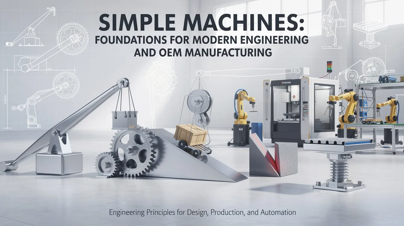
Simple Machines: Foundations for Modern Engineering and OEM Manufacturing
Introduction to Simple Machines
Every crane on a construction site, every press in a stamping shop, and every robotic arm on an assembly line owes its capability to a handful of ancient principles. A simple machine is a mechanical device that can multiply force or change the direction of a force applied to it, making tasks easier and forming the building blocks of more complex machines. Simple machines have few or no moving parts, yet they underpin nearly every piece of equipment in modern manufacturing. There are six types of simple machines: lever, pulley, wheel and axle, inclined plane, wedge, and screw. These six classical simple machines were formally categorized during the Renaissance, building on foundational work by the Greek philosopher Archimedes in the 3rd century BCE, and they remain just as relevant today.
At Anebon Metal Products Limited, we precision-machine the components that bring these principles to life – fulcrum pins for levers, precision shafts for wheel and axle assemblies, threaded lead screws, pulley sheaves, and countless other parts used in aerospace, medical devices, robotics, and industrial machinery. This article explores each of the six simple machines, explains the concept of mechanical advantage, shows how simple machines combine into compound machines, and connects these physics fundamentals to the practical realities of OEM part design and manufacturing.
The Six Simple Machines and Mechanical Advantage
All six basic types of simple machines operate on a single core idea: mechanical advantage. Mechanical advantage is the ratio of output force to input force, and it describes how much a device amplifies the force exerted by an operator. Simple machines make work easier by changing the magnitude or direction of a force – and sometimes both at once.
Here are the six simple machines and what each does:
-
Lever – pivots around a fixed point to amplify or redirect force
-
Inclined plane – a flat surface set at an angle to reduce lifting effort
-
Wheel and axle – converts rim force into higher-torque axle rotation
-
Pulley – a grooved wheel with a rope or belt that redirects or reduces force
-
Wedge – two inclined planes joined to split or clamp materials
-
Screw – an inclined plane wrapped helically to convert rotational motion into linear motion
The trade-off is universal: when a machine increases the output force, it demands that the input force applied travels a longer distance. Pushing a crate up a long ramp requires less force than lifting it straight up, but you cover more distance moved in the process. This proportional decrease in force comes at the cost of increased travel – energy is conserved in an ideal system.
In real-world mechanical systems, friction, material deformation, and wear consume some of that energy. That is exactly why material choice, tight tolerances, and surface treatments matter so much when manufacturing simple machine components. Mechanical advantage allows less force to move an object, but only if the parts are made well enough to minimize parasitic losses.
The Lever
A lever is a rigid bar that rotates around a fixed point – called the fulcrum or pivot point – to amplify or redirect force. A lever amplifies force by pivoting around a fulcrum, and it is one of the simplest mechanisms in engineering. The concept of a lever’s force amplification is often called leverage.
There are three classes of levers, each defined by the relative positions of load, effort, and fulcrum:
|
Class |
Fulcrum Position |
Example |
Typical Advantage |
|---|---|---|---|
|
First |
Between effort and load |
Crowbar, seesaw |
Can give large mechanical advantage |
|
Second |
Load between fulcrum and effort |
Wheelbarrow, nutcracker |
Usually MA > 1 (force multiplier) |
|
Third |
Effort between fulcrum and load |
Tweezers, fishing rod |
Speed/distance advantage |
Moving the fulcrum closer to the load increases mechanical advantage. Levers can multiply force applied by a factor of distance – a longer effort arm relative to the load arm means a smaller input force can lift heavy objects. Levers allow small forces to lift heavy weights, which is why lever-based tools remain indispensable in factories and workshops worldwide.
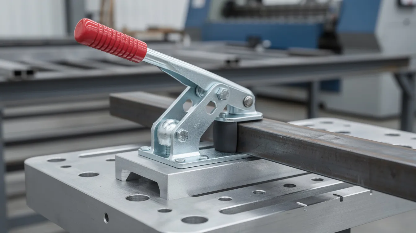
In OEM and industrial settings, you encounter levers everywhere: press handles, toggle clamps on welding jigs, manual material-handling devices, and linkage arms inside automation cells. These components need high stiffness, precise pivot point locations, and controlled surface finish to minimize friction.
At Anebon, lever arms, fulcrum pins, and bracket components are CNC machined from aluminum, stainless steel, or tool steel with tolerances as tight as ±0.002 mm. That level of precision ensures smooth, predictable motion and long service life even under repeated high-load cycling. The term refers to real, measurable manufacturing accuracy – not marketing language.
The Inclined Plane (Ramp)
An inclined plane is a flat surface set at an angle that connects a lower level to a higher level, allowing loads to be raised using less force than lifting objects vertically. The trade-off is distance: a gentler slope (longer ramp) reduces the force required but increases the path length.
Inclined planes reduce the force needed to lift objects, and you see them everywhere in the world of logistics and manufacturing:
-
Cargo ramps at loading docks that let forklifts and pallet trucks move heavy objects between truck bed and warehouse floor
-
Wheelchair ramps designed to meet ADA accessibility standards
-
Switchback roads in mountainous regions, where long zigzag paths replace steep, direct climbs
-
Conveyor infeed chutes that feed raw material into CNC machining cells
Every time you push something up a ramp instead of lifting it straight up, you trade distance for force – the force needed drops as the ramp lengthens. Inclined planes reduce force needed to lift objects vertically, which is why they remain among the most practical simple tools in everyday engineering.
It is worth noting the underlying mathematical similarity between the inclined plane and two other simple machines: the wedge (essentially two inclined planes joined back-to-back) and the screw (an inclined plane wrapped around a cylinder). All three share the same geometric principle of trading distance for force.
Components such as ramp brackets, guide rails, and wear plates for inclined systems can be produced via CNC machining or sheet metal fabrication, with optional surface treatments like anodizing, hardening, or low-friction coatings to resist abrasion and extend service life.
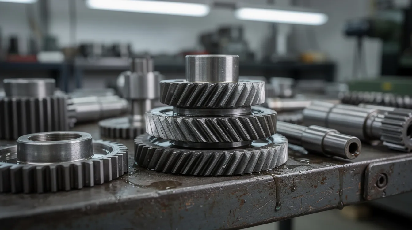
Wheel and Axle
The wheel and axle is a simple machine consisting of a larger wheel rigidly attached to a smaller shaft (the axle) so that a force applied at the wheel’s rim turns the axle with increased torque. The mechanical advantage equals the ratio of wheel radius to axle radius – a modest input force at the rim becomes a much larger force exerted at the axle.
Wheel and axle systems reduce friction in transport, which is one reason this device transformed civilization. Concrete examples include:
-
Car wheels transferring engine torque to the road
-
Handwheels on machine tools for precise manual feed adjustments
-
Door knobs converting a light grip into rotational motion sufficient to retract a latch
-
Winch drums used in material handling
-
Gear-driven wheel and axle assemblies inside factory automation systems and AGVs
Wheel and axle mechanisms often work alongside other simple machines – pulleys, levers, gears – to change the direction of motion and distribute loads across mechanical systems. A single load force at the wheel rim can be converted into controlled axle torque for driving conveyors, rollers, or drive wheels in robotic platforms.
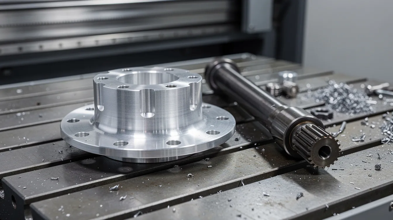
At Anebon, precision-machined axles, hubs, and gear blanks are produced via CNC turning and 5-axis milling from materials like hardened steel, aluminum alloys (6061, 7075), and engineering plastics such as POM and PEEK. Concentricity and cylindricity are tightly controlled to prevent vibration and premature bearing wear – critical for high-RPM or high-load applications in robotics and conveyor systems.
Pulleys and Changing the Direction of Force
A pulley is a grooved wheel combined with a rope, belt, or chain that can change the direction of a force and, in multi-pulley systems, reduce the input force needed to lift loads. Pulleys change the direction of force to lift objects, making them essential force amplifiers in construction, maintenance, and manufacturing.
There is an important distinction between pulley types:
-
A fixed pulley only changes the direction of the single applied force – you pull down to lift a load up. No force multiplication, but a significant ergonomic and safety benefit.
-
A movable or compound pulley (block and tackle) distributes the load across multiple rope segments, providing real mechanical advantage. Compound pulleys can achieve a large mechanical advantage – for example, a six-line block and tackle lets an operator lift a load six times heavier than the force applied, at the cost of pulling six times more rope.
Specific examples include construction cranes on high-rise projects, workshop hoists, overhead gantry systems in assembly plants, and elevator counterweight systems. Pulleys change the direction of force for lifting, allowing operators to pull downward – leveraging body weight and gravity – rather than straining upward. This is safer and reduces fatigue on assembly lines and in maintenance workshops.
Pulley housings, sheaves, side plates, and bearing seats can be CNC machined or fabricated from aluminum, stainless steel, or carbon steel. Anebon’s ISO 9001:2015 quality assurance processes ensure consistent fit between sheave grooves, bearings, and shafts – dimensional reports covering runout, concentricity, and position are standard.
Wedge and Screw: From Cutting to Fastening
A wedge is essentially two levers – or more precisely, two inclined planes joined back-to-back – that convert a pushing force into lateral forces capable of splitting or clamping materials. A wedge is used to split or lift objects by applying force along its length, making it one of the simplest mechanisms for concentrating energy into a narrow edge.
Wedges are used for splitting and lifting objects across manufacturing and maintenance:
-
Cutting tools and chisels for material removal
-
Punches and press brake tooling for sheet metal forming
-
Shims for leveling heavy machinery on factory floors
A screw is an inclined plane wrapped around a cylinder, converting rotational motion into linear motion or fastening force. The Italian scientist Archimedes studied this device extensively, and his water-lifting Archimedean screw remains in use today. The mechanical advantage of a screw is based on its thread pitch – a finer pitch yields greater force amplification but requires more turns to achieve the same linear travel. The velocity ratio of a screw relates input rotation to output linear displacement.
Screw examples in engineering and OEM contexts include:
-
Lead screws on CNC milling machines providing precise axis feed
-
Jacks used for lifting vehicles or heavy equipment
-
Bone screws in medical devices that must meet strict biocompatibility and dimensional standards
-
Threaded fasteners holding sheet metal enclosures together
Anebon produces precision threaded components – lead screws, custom bolts, inserts – via CNC turning and milling from titanium, stainless steel (304, 316, 17-4 PH), and engineering plastics. Surface treatments like passivation, anodizing, and plating improve wear and corrosion resistance, directly affecting how efficiently a screw converts applied force into clamping or linear force.
From Simple Machines to Compound Machines
A compound machine combines two or more simple machines into a single device that can perform more complex tasks with greater efficiency and control. Most complex tools and machines combine multiple simple machines, and understanding how these different simple machines interact is essential for OEM product development.
Examples of compound machines include wheelbarrows and bicycles. Here are a few concrete cases:
-
Scissors – a lever combined with a wedge (the blade edge)
-
Wheelbarrow – a lever combined with a wheel and axle
-
Bench vise – a screw combined with a lever
-
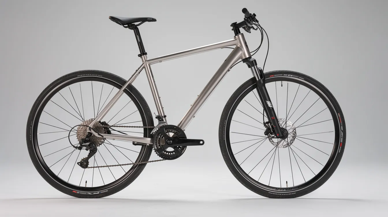
Bicycle – a bicycle uses wheels, levers, and pulleys as compound machines, integrating chain-and-sprocket drives, handlebars, and brake levers into a single vehicle
-
CNC machine tool – lead screws, levers, wheels and axles, and belt-driven pulleys integrated with motors and digital controls create more complex machines capable of micron-level material removal
The mechanical advantage of a compound machine is the product of its simple machines’ advantages. If a lever provides MA = 3 and a screw provides MA = 10, the combined system ideally delivers MA = 30. However, friction accumulates at every interface, so actual performance depends on material quality, surface finish, and assembly precision. Compound machines can amplify force or change the direction of force – often both simultaneously.
For OEM engineers, understanding this matters because it enables better design of jigs, fixtures, press tools, and automation modules. A well-designed compound machine is easier to operate, cheaper to maintain, and more reliable over its service life.
Anebon supports customers from rapid prototyping to full production of parts for compound machines, providing DFM feedback to optimize lever arms, brackets, housings, and motion components for manufacturability and durability. The complete dynamic theory of how simple machines interact within a compound assembly may be complex, but the manufacturing principles are straightforward: hold tight tolerances, choose the right material, and control surface finish.
Designing and Manufacturing Simple-Machine Components with Anebon
The physics of simple machines – force amplification, direction change, distance-force trade-offs – translate directly into engineering specifications on a part drawing. Every lever arm needs a defined stiffness. Every axle needs concentricity. Every threaded screw needs pitch accuracy. Turning these basic tools from concept into functional hardware demands precision manufacturing.
Anebon’s CNC milling, CNC turning, and 5-axis machining capabilities enable tight tolerances (as precise as ±0.002 mm) and complex geometries for custom simple-machine components used across aerospace, medical, automotive, robotics, and industrial machinery applications.
The material range covers the demands of virtually any simple machine application:
|
Material Category |
Common Grades |
Typical Use |
|---|---|---|
|
Aluminum alloys |
6061, 7075 |
Lightweight lever arms, pulley housings, wheel hubs |
|
Stainless steels |
304, 316, 17-4 PH |
Corrosion-resistant shafts, screw components, medical parts |
|
Titanium alloys |
Ti-6Al-4V |
High strength-to-weight aerospace and medical screws |
|
Copper / Brass |
C360, C110 |
Low-friction bushings, electrical contacts |
|
Engineering plastics |
POM, PEEK, PTFE |
Self-lubricating bearings, lightweight pulleys |
Complementary processes include die casting for higher-volume wheel hubs or housings and sheet metal fabrication for brackets, guards, and mounting plates that surround or support simple-machine elements.
Quality and reliability are backed by ISO 9001:2015 and ISO 14001:2015 certifications. In-process inspections occur every two hours during production, and final QA reports cover all critical dimensions. Prototyping turnaround for 5-axis CNC parts is typically 3–7 working days, allowing design engineers to iterate quickly before committing to full OEM production runs. The term simple machine originated in ancient Greece, but manufacturing these basic types of components to modern standards requires decidedly modern equipment and quality systems.
Conclusion: Simple Machines as Strategic Design Tools
The six simple machines – lever, inclined plane, wheel and axle, pulley, wedge, and screw – are not just textbook concepts. They are practical design tools that shape how engineers create everything from handheld instruments to multi-ton industrial presses. Every mechanical device in a factory, every piece of automation equipment on a production floor, traces its lineage back to these simplest mechanisms.
The benefits are concrete and measurable: reducing the force required to move or lift heavy objects, improving ergonomics for operators, allowing engineers to change the direction of motion to suit workspace constraints, and forming the backbone of compound machines used across factories and product lines worldwide. Whether you are working at the other end of a design table from a robotics team or specifying parts for a medical device, these principles inform every decision about load paths, material selection, and part geometry.
For design engineers and R&D teams, a solid grasp of how simple machines work – and how they combine – leads to mechanisms, jigs, and fixtures that are easier to manufacture, simpler to maintain, and more cost-effective to produce at scale.
If you are developing products that rely on levers, screws, pulleys, or any combination of these basic tools, Anebon Metal Products Limited is ready to help. From DFM feedback and rapid prototyping through full-volume OEM production, we bring the precision, materials expertise, and quality certifications needed to turn simple-machine principles into reliable, high-performance parts. Reach out to request a quote and see how we can support your next project.