Understanding the Raking Angle: Best Practices for Precision Machining
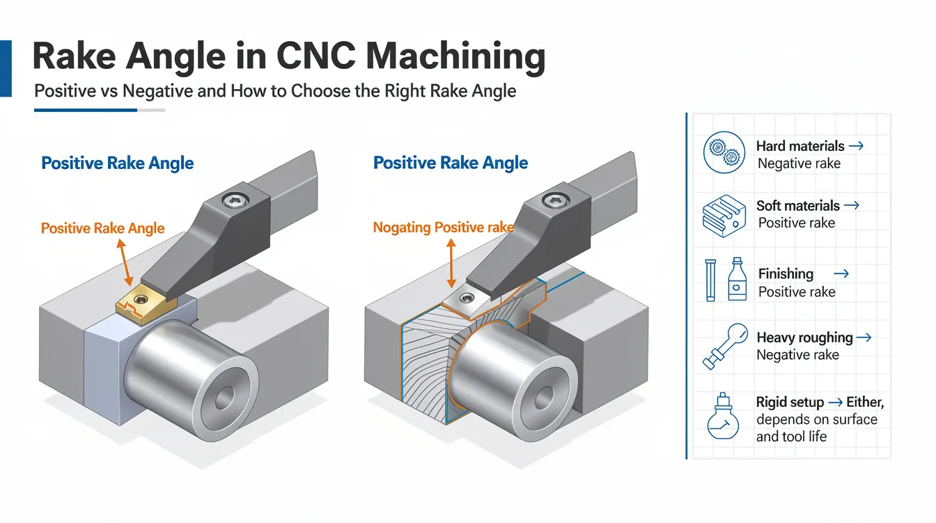
Rake Angle in CNC Machining: Positive vs Negative and How to Choose the Right Rake Angle
Choosing the right rake angle on a cutting tool can mean the difference between a flawless finished part and a scrapped workpiece. This guide covers positive, negative, and zero rake angles, explains how each affects chip formation, tool life, and surface finish, and offers material-specific recommendations from Anebon Metal Products Limited’s precision machining experience.
Quick Answer: What Is Rake Angle and Why It Matters in CNC Machining
Rake angle is the angle between the rake face of the cutting tool and a line perpendicular to the workpiece surface or feed direction. It is a vital geometric parameter that dictates how a cutting tool engages the material and controls how the chip slides off the cutting edge.
Choosing the correct rake angle-positive, negative, or zero-directly affects surface finish, tool life, power consumption, and chip evacuation. Rake angle influences cutting forces, chip evacuation, and tool longevity in every precision OEM part. In Anebon’s CNC machining projects, including aluminum 6061 aerospace housings and stainless steel 304 medical components, fine-tuning rake angles has been a key lever to achieve ±0.002 mm tolerances and stable production.
-
Positive rake angle: choose when machining soft materials like aluminum, brass, or plastics where lower cutting forces and smooth chip flow matter most.
-
Negative rake angle: choose when edge strength is critical, such as in hardened steels, cast iron, or titanium.
-
Zero rake angle: choose as a starting point for general-purpose work or when simplifying tool inventory.
Note: The term “rake” appears in other fields too. In automotive design, rake refers to the setting of the vehicle’s rear higher than the front for aerodynamics, and calculating rake angle in vehicles involves measuring the height difference between front and rear. In construction, the rake angle is used when building a rake wall that follows the slope of a gable roof, where rake walls form a right triangle based on the roof’s pitch. This article focuses exclusively on rake angle in machining.
Fundamentals: Definition of Rake Angle and Cutting Edge Geometry
The rake face-also called the cutting face-is the surface of the tool over which the chip slides during machining. The cutting edge is the line where the rake face meets the flank. Rake angle is the angle of the cutting tool face, measured relative to a line perpendicular to the cutting speed or feed direction. Rake angle affects chip formation and cutting forces across every machining operation.
Other tool angles work alongside rake angle. The relief angle (or clearance angle) prevents rubbing behind the cutting edge. The wedge angle is formed between the rake face and the flank. Together, relief angle + rake angle + wedge angle define the edge’s sharpness and strength:
-
A larger positive rake angle creates a sharper but weaker cutting edge-suited for shearing ductile materials.
-
A negative rake angle creates a blunter but stronger cutting edge-suited for absorbing impact in hard materials.
In single-point turning tools, the side rake angle is the primary reference. In milling cutters, radial and axial rake angles along each axis influence chip evacuation and cutting forces differently.
Types of Rake Angles: Positive, Negative, and Zero
Rake angles are classified as positive, zero, or negative. Tool catalogs typically list ranges such as +5° to +20° for positive rake, 0° for neutral, and −5° to −15° for negative rake, depending on insert geometry and cutting tool material.
Positive Rake Angle: When and Why to Use It
A positive rake angle allows the cutting tool to slice material rather than plow it, which reduces cutting force and heat generation. Positive rake angles are best for ductile materials. A positive rake angle reduces cutting force and power usage, and tools with high positive rake angles reduce necessary cutting forces for lower horsepower machines.
Common ranges: +10° to +20° side rake angle for aluminum 6061/7075, brass, copper, and engineering plastics.
Advantages: improved surface finish, easier chip flow, less power required, reduced chatter, better tool life in soft materials. Positive rake angles create thin, curled chips during cutting, improving chip evacuation. Positive rake angles improve cutting efficiency and surface finish.
Limitations: weaker cutting edge prone to chipping in hard or abrasive materials; less suited for heavy interrupted cuts. Larger rake angles reduce cutting force but may damage cutting edges under shock loads.
At Anebon, positive rake inserts are standard for thin-walled aluminum housings where minimizing cutting pressure prevents dimensional distortion during aerospace prototypes.
Negative Rake Angle: Where Edge Strength Matters
A negative rake angle leans the tool face away from the cut, increasing the wedge angle and producing a stronger cutting edge. Negative rake angles suit brittle materials like high-carbon steel and are better for cutting hard materials like titanium. A negative rake angle increases edge strength for harder materials.
Practical ranges: −5° to −10° radial rake on carbide inserts for hardened steels, cast iron, and nickel superalloys. Negative rake angles produce thicker, segmented chips. Negative rake angles increase cutting force and friction during machining, generating higher temperatures and requiring more friction management through coolant strategy.
CBN and ceramic inserts for hard turning above 55 HRC often require negative side rake angles to keep the cutting edge supported. Anebon uses these tools for automotive and robotics OEM production runs in hardened steel to maximize tool life and reduce downtime.
Zero or Neutral Rake Angle: A Compromise Option
Neutral rake angles are perpendicular to the feed direction, with the cutting face effectively at 90° to the feed line. A zero rake angle is also used for simplifying the design of certain form tools.
Where used: general-purpose inserts, medium carbon steels, initial process development.
Advantages: simple tool design, decent edge strength, versatile across materials. Disadvantages: higher cutting forces than positive rake, less efficient chip evacuation, potentially requiring more power.
Anebon’s engineers sometimes start with neutral rake inserts for new OEM projects and then refine to more positive or more negative geometry after initial cutting trials.
Side Rake Angle, Cutting Edge Angle, and Other Related Terms
The side rake angle is measured in the plane perpendicular to the cutting edge, affecting chip thickness and the direction of chip flow across the rake face. Adjusting it modifies chip formation, cutting forces, and the chip evacuation path. The tool cutting edge angle-the angle between the main cutting edge and the feed direction-determines how load distributes along the edge and is essential for correct tool nose radius compensation in CNC programs.
Chip Evacuation and Chipbreaker Geometry
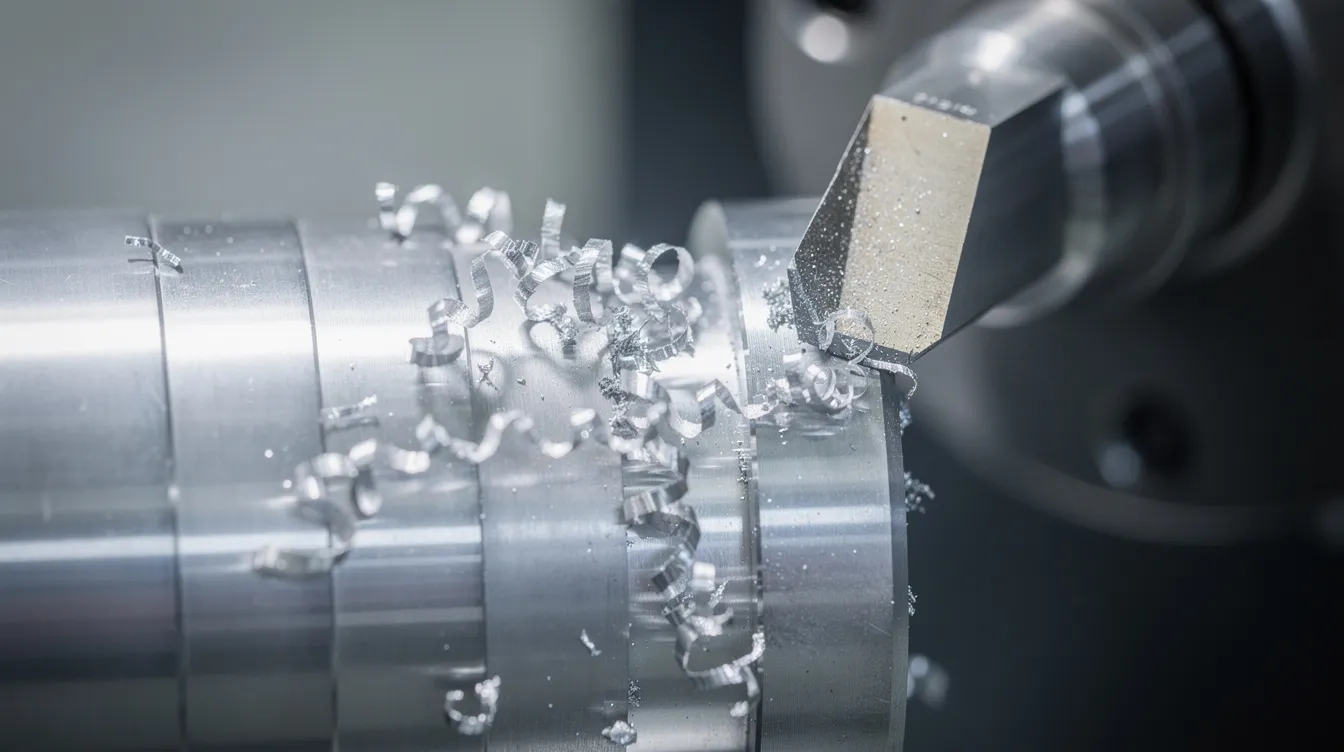
Chip evacuation is a major quality and safety factor, especially in deep pockets and unattended cycles. Rake angle directly shapes chip thickness and curl. Chipbreaker geometry built into carbide inserts modifies the effective rake by introducing micro-angles and grooves on the rake face. Toolholders with different inclination angles further change the effective cutting angle at the workpiece. Positive rake angles create thinner, curled chips for better evacuation in deep-pocket aluminum machining.
Side Rake Angle for CBN and Ceramic Inserts
CBN and ceramic cutting tools are harder but more brittle than carbide. They typically use negative side rake angles around −8° or lower to maintain a stable wedge behind the cutting edge during hard turning. Manufacturers publish effective side rake and cutting angle data for each insert geometry-interpreting these charts is crucial for selecting the correct rake angle.
Correct Rake Angle by Material and Operation
There is no single right rake angle. Positive rake angles are better for soft materials while negative rake angles are better for harder metals. A proper rake angle decreases the power required to remove material. The table below suggests typical ranges:
|
Material |
Positive Rake |
Neutral |
Negative Rake |
|---|---|---|---|
|
Aluminum alloys |
+12° to +25° |
+5° to +10° |
Rarely needed |
|
Brass / Copper |
+10° to +20° |
+5° to +10° |
0° to −5° |
|
Low-carbon steel |
+10° to +15° |
+5° to +10° |
−5° to 0° |
|
Stainless steel / Nickel alloys |
+5° to +12° |
0° to +5° |
−5° to −10° |
|
Cast iron |
0° to +5° |
0° to +3° |
−5° to −10° |
|
Hardened steel (HRC 50+) |
Rarely used |
0° to +5° |
−5° to −20° |
Anebon’s DFM feedback to OEM clients includes recommendations on material and rake angle combinations that balance cost, machinability, and performance.
Rake Angle in CNC Turning, Milling, and Drilling
In CNC turning, side rake angle and back rake angle define how chips flow over a single-point tool, impacting surface roughness and tool wear. Research on mild steel turning showed that a +20° rake achieved the longest tool life and best surface finish compared to lower angles.
In CNC milling, radial rake angle and axial rake angle in end mills determine entry shock, chip thickness, and spindle load. For drilling, the helix angle and flute design set a combination of rake angle and side rake angle that control chip evacuation from deep holes.
At Anebon, cutting speed selection and rake angle decisions are made together to ensure consistent performance from prototype to full production.
How Rake Angle Affects Tool Life, Surface Finish, and Power Consumption
Small changes in rake angle produce large differences in tool wear, surface roughness, and power requirements. A larger rake angle reduces cutting force during machining. Larger rake angles also reduce friction and lower cutting temperatures. A more positive rake angle reduces cutting forces and extends tool life in softer materials while improving surface finish by reducing vibration. A machine running positive rake tools draws less power.
A more negative rake angle generates higher cutting forces and higher temperatures but reinforces the cutting edge in hard or abrasive materials. Incorrect rake angles can cause premature wear or catastrophic tool failure. Poor selection leads to crater wear on the tool face, edge chipping, and dimensional drift-all of which raise scrap rates.
Chip Evacuation, Safety, and Automation
Reliable chip evacuation is essential for part quality, operator safety, and lights-out CNC machining. Correct rake angle and chipbreaker selection create chips that break and clear predictably. Rake angles control how easily chips form and break. Anebon configures rake angles and chip control features to suit long-duration production runs with automatic part loading, minimizing operator intervention.
Practical Selection of Rake Angles with Anebon Metal Products Limited
Optimal rake angle selection is a collaborative effort between tool suppliers, process engineers, and OEM customers. Anebon’s engineers review 3D models, 2D drawings, and material specifications to determine toolpaths, cutting tools, and rake angles that meet required tolerances and delivery timelines.
For rapid prototyping projects, Anebon starts with forgiving positive rake tools to shorten setup time, then refines insert geometry for full-scale production. Across aluminum, titanium, stainless steels, and plastics, every material gets a tailored chip control strategy.
Ready to optimize your next project? Submit your drawings or request a quote so Anebon can recommend the right rake angles, tooling, and machining strategies for your specific OEM parts-whether you need a single prototype or a stable, high-volume production run.