Understanding the Properties and Applications of Bent Steel Sheet
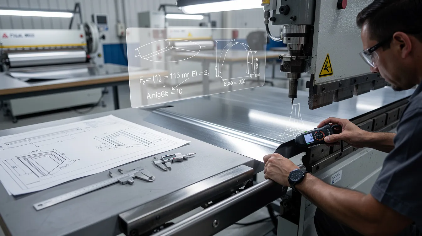
Bent Steel Sheet: Design, Bending Methods, and Precision Fabrication
Bending steel sheets is one of the most common manufacturing operations in OEM production today. From automotive brackets to medical device frames, the ability to transform a flat sheet of steel into a precise three-dimensional shape drives modern product design across nearly every industry. This guide covers everything design engineers and procurement teams need to know about bent steel sheet – from core bending concepts and material behavior to design rules, tolerances, and how to work with an experienced fabrication partner.
Overview of Bent Steel Sheet in Modern Manufacturing
A bent steel sheet is a flat piece of steel that has undergone plastic deformation – reshaped through controlled force without removing material – into angles, channels, U-profiles, Z-bends, brackets, enclosures, or other formed geometries. Bent steel sheets are foundational in construction and manufacturing, serving as the backbone for everything from machine guards to vehicle chassis components.
Since 2010, Anebon Metal Products Limited has supplied precision bent sheet metal parts to overseas OEMs in industries including automotive, electronics, medical devices, industrial machinery, robotics, and aerospace. Anebon offers sheet metal bending, CNC machining, die casting, and full fabrication services from its Dongguan facility, certified to ISO 9001:2015 and ISO 14001:2015 standards.
This article focuses specifically on bending sheet steel – cold-rolled, hot-rolled, stainless steel, and galvanized variants – rather than generic metal bending or other forming processes. Here is what we will cover:
-
Bend radius fundamentals – what drives minimum bend radius and how material thickness, grade, and grain direction play a role.
-
Bending methods – when to use air bending, bottom bending, coining, or folding, and how each affects part quality.
-
K factor and flat patterns – how the k factor, bend allowance, and bend deduction govern accurate blank development.
-
Design rules – minimum flange length, feature placement near the bend line, and relief strategies.
-
Tolerances and QC – what angular and linear tolerances to expect from CNC press brake operations.
-
Material selection – choosing between mild steel, stainless steel, galvanized, and aluminum for your application.
-
Working with Anebon – DFM feedback, instant pricing responsiveness, and scaling from prototypes to production.
What Is Bent Steel Sheet and How Is It Produced?
Bent steel sheet starts as flat steel sheet or plate that is formed into angles, channels, U-profiles, Z-bends, and complex brackets through a bending process that does not remove material. The result is a near-net-shape component ready for assembly, welding, or surface finishing.
Anebon typically handles steel sheet in thicknesses from about 0.5 mm up to 12 mm for most OEM bent sheet components. Here are the key applications and how bent parts are formed:
-
Automotive – the automotive industry uses bent steel for vehicle body panels and brackets, as well as structural reinforcements. Bending enables the creation of lightweight shapes that absorb impact energy in crash zones.
-
Electronics – cold-rolled steel enclosures and housings (typically 1.2–2 mm) with folded edges that eliminate sharp angles and protect internal components.
-
Medical devices – stainless steel cover plates and frames requiring clean bends and passivated surfaces for sanitary environments.
-
Aerospace – the aerospace industry utilizes bent steel for components like wings and propellers, as well as precision brackets requiring tight tolerances.
-
Industrial machinery – machine enclosures and protective covers in manufacturing, plus heavy machine bases with stiffening flanges from 3–5 mm hot-rolled steel.
-
Construction and HVAC – bent sheets are used for ventilation ducts and HVAC systems to shape airflow paths. Applications also include roofing and cladding materials, drainage facilities, and bridge components. Cold-formed steel members are used for building frames and trusses.
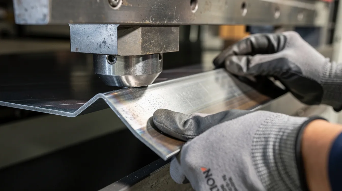
The typical production sequence at Anebon follows a clear path:
-
Accept flat sheet or coil stock.
-
CAD review and flat pattern development with proper bend allowance and bend deduction values.
-
Laser cutting or CNC punching to create the blank profile.
-
Edge finishing and deburring.
-
Bending on a CNC press brake using air bending, bottom bending, or other methods.
-
Optional welding (spot, MIG/TIG), then surface treatment (powder coating, plating, galvanizing, passivation).
Bent steel sheets are produced in batches from rapid prototypes (1–20 pieces) through full production runs of 1,000+ pieces. Concrete examples include a control panel door with 3–5 bends of 90° made from 3 mm hot-rolled steel, or a stainless cover for a medical device with multiple U-shapes in 1.2 mm sheet.
Core Bending Concepts: Bend Radius, K-Factor, Bend Allowance, and Bend Deduction
Accurate flat patterns for bent steel sheet depend on understanding how the material stretches and compresses during forming. Four interrelated concepts govern this: inside bend radius, k factor, bend allowance, and bend deduction.
-
Inside bend radius – the radius measured at the material’s inner surface in the bend. Outside bend radius equals the inside radius plus material thickness. The minimum bend radius increases with material thickness and hardness – for cold-rolled mild steel up to 3 mm, a common rule of thumb is a minimum inside bend radius of roughly 1× the sheet thickness. For thicker or harder grades, expect 1.5–3× thickness.
-
K factor – the k factor predicts material stretch during bending by expressing where the neutral axis sits relative to the total thickness. A k factor of 0 means the neutral axis is at the inside face; 0.5 means dead center. For steel in air bending, typical values range from 0.33 to 0.45. The k factor varies based on material properties and bending method – tighter radii push it lower, while bottoming or coining shifts it higher.
-
Bend allowance – bend allowance measures material used in the bend arc. It represents the length of material consumed along the neutral axis as the sheet forms the desired angle. The bend allowance formula is: BA = (θ × π / 180) × (R + K × T), where θ is the bend angle, R is the inside bend radius, K is the k factor, and T is the thickness.
-
Bend deduction – bend deduction is subtracted from flange lengths for flat patterns. It accounts for the difference between the sum of outside flange dimensions and the actual flat length needed.
Worked example: Consider a 2 mm thick cold-rolled steel part, bent with a specific radius, air bent to a 90° bend angle with an inside bend radius of 2 mm and a k factor of 0.38.
-
Bend allowance = (90 × π / 180) × (2 + 0.38 × 2) = 1.5708 × 2.76 ≈ 4.34 mm.
-
Outside setback for a 90° bend = R + T = 2 + 2 = 4 mm.
-
Bend deduction = 2 × 4 − 4.34 = 3.66 mm.
-
If flanges measured to the outside are 50 mm and 30 mm, the flat blank length = 50 + 30 − 3.66 ≈ 76.34 mm.
Why does this matter? If the bend allowance or bend deduction is wrong – say you use a k factor of 0.50 when the material actually behaves at 0.40 – the flat pattern ends up too long or too short. On multi-bend components like U-channels, these errors stack with each bend, causing flanges that do not meet dimensional specs. The result is rework, scrap, and delayed delivery. Bend radius also affects the minimum bend angle required to achieve a given geometry without excessive springback risk.
Key Bending Methods for Steel Sheet
Choosing the right bending method directly affects achievable tolerances, surface finish, and cost. V-bending is the most common method for bending sheet metal, but several variations exist. Anebon primarily uses CNC air bending and bottoming for their combination of flexibility, repeatability, and controllable bending force.
-
Air bending – the punch presses the workpiece into the v die without fully closing the material into the v shape. Advantages include lower tonnage requirements, the ability to achieve different angles and bend radii from the same tooling, and rapid changeover. Typical for 1–8 mm sheet steel. The v opening of the die determines the effective bend radius. Springback is more pronounced, so operators program compensation. Cold bending is done at room temperature for high accuracy, which is the standard for air bending.
-
Bottom bending – the material is seated fully in the v die, reducing springback and producing tighter angle tolerance (often ±0.5° on critical bends). Anebon uses this for thicker materials like 6–10 mm plates or when angular precision is non-negotiable. The trade-off is higher bending force and greater tooling stress.
-
Coining – extremely high tonnage permanently thins the material at the bend line through strain hardening. Rarely used in production because of tool wear and energy consumption, but justified for very small inside bend radius requirements on thin (0.8–1.0 mm) stainless steel where springback must be nearly eliminated.
-
Folding and wiping – used for long panels and enclosure sides. Folding minimizes surface damage on painted or brushed stainless steel, making it suitable for decorative parts. Wiping is faster but can scratch the surface, so it is reserved for parts where finish is less critical.
-
Three-point bending and rotary bending – specialized methods. Three-point bending offers very precise angle control on thick plate with short bends. Rotary bending uses rotating dies or urethane pads for scratch-free forming of pre-coated or decorative sheet steel, protecting the surface while achieving the desired angle.
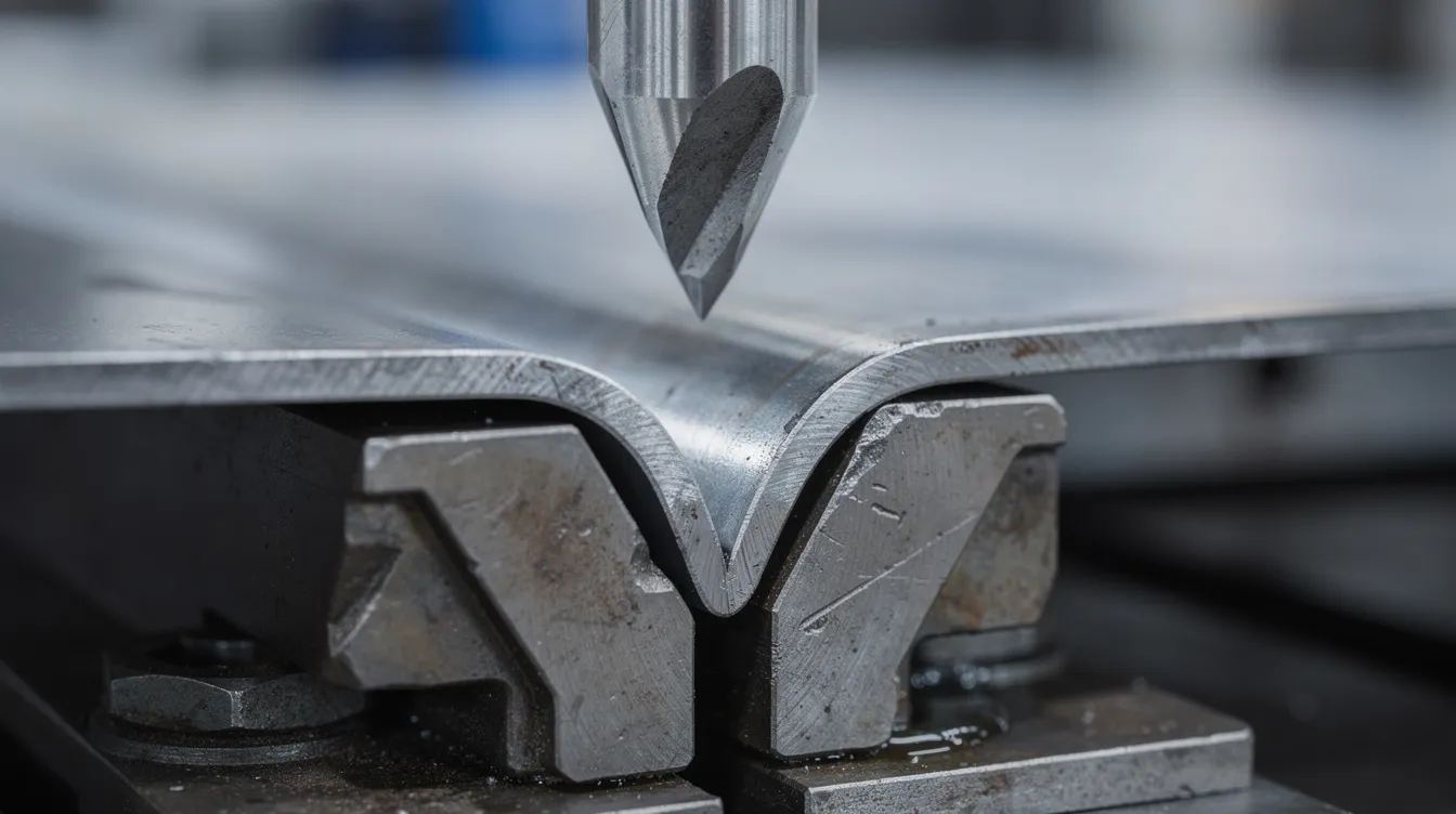
Press brake machines can bend sheet metal into precise angles across all of these methods. The choice depends on the material type, sheet thickness, required tolerances, and surface finish expectations.
Material Behavior: Grain Direction, Springback, and Minimum Inside Bend Radius
Steel sheet behavior during bending is not isotropic. The grain direction from the rolling process, along with thickness and grade, significantly influences cracking risk, bend radius limits, and springback. Precise bending processes are essential for avoiding material breaking, especially on harder or thicker grades.
-
Grain direction – steel sheet develops a directional grain structure during mill rolling. Bending transverse to the grain (perpendicular to the rolling direction) typically allows a tighter inside bend radius because the material stretches more evenly. Bending against the grain increases cracking risk – longitudinal bends (parallel to the rolling direction) may need a larger bend radius or even larger bend radii across the part to prevent fracture. For a practical example, a 4 mm stainless steel bracket should have bends oriented transverse to the grain to reduce cracking risk. More detail on stainless applications is available in Anebon’s guide on how to bend stainless steel sheet metal.
-
Springback – springback occurs when metals try to regain their original shape after the bending force is released. The amount of elastic recovery is related to material yield strength – high strength materials and stainless steel spring back more (4–7° for stainless vs. 2–3° for mild steel targeting 90°). Designers may specify that parts are over bent (e.g., bending to 92° to achieve a final 90° angle). Anebon manages this through springback compensation techniques programmed into CNC press brake routines.
-
Minimum inside bend radius rules of thumb – for 2 mm low-carbon steel bent transverse to grain, minimum inside bend radius ≈ 1× thickness (≈ 2 mm). For 5–8 mm thick plate or high-strength structural steels, 1.5–3× thickness is recommended. Localized stress can limit inside bend radius tightness, especially where the edges have been hardened by thermal cutting.
-
Heat-affected zones – laser cutting and plasma cutting can harden the cut edge. Anebon keeps critical bend lines a safe distance from heat-affected zones and dresses edges on thick plates before bending to prevent crack initiation.
-
Hot forming – hot bending occurs above the metal’s recrystallization temperature. For heavy sections like 20–25 mm structural steel plates, preheating or hot working bends metal above its recrystallization temperature to enable tight bends without cracking. However, most OEM bent sheet metal parts are cold-formed at room temperature for dimensional accuracy and cost efficiency.
Design Rules for Bent Steel Sheet Parts
Good DFM practices for bent steel sheet reduce cost, prevent cracks and distortion, and make CNC press brake setups more reliable. Bend quality is affected by multiple factors including material thickness and die size, so aligning your design to standard tooling and proven guidelines is critical.
-
Uniform thickness – keep wall thickness uniform across the part. Mixing drastically different thicknesses in one bent component forces compromise in v die selection and bend radius, increasing setup complexity and cost.
-
Minimum flange length – for air bending mild steel, minimum flange length should be at least 2.5× material thickness plus the inside radius. If leg height is too small relative to the punch or die geometry, flanges may collapse or the tool may collide with the part. For 2 mm steel with a 2 mm radius, minimum flange length ≈ 2.5 × 2 + 2 = 7 mm.
-
Bend radius selection – avoid sharp bends on heavy-gauge steel. Favor standard radii (1× or 1.5× thickness) that match common tooling. Standard choices reduce cost and lead time; exotic radii require custom tooling and longer setup.
-
Features near bend lines – maintain a minimum distance of at least 2× material thickness from the tangent line of the bend for holes, slots, and notches. Features placed too close to the bend line will distort or tear as the material stretches during forming. Provide bend reliefs for deep flanges and U-profiles.
-
Successive bends and Z-bends – leave enough spacing so one flange does not hit the punch or die during the bending sequence. For Z-bends, minimum step heights should be at least 4× material thickness to avoid tool interference.
-
Hems, curls, and U-profiles – hems stiffen edges and remove sharp corners. On thicker steels, design open or teardrop hems instead of tight closed hems, which are difficult to form and prone to cracking. Avoid very deep, narrow U-channels that wrinkle during forming.
Properly formed bends can improve structural integrity and aesthetic quality – but only when the design respects the material’s limits.
Process Flow at Anebon: From Laser Cutting to Precision Bending
Anebon’s integrated workflow covers quoting, DFM review, laser cutting, bending, secondary operations, inspection, and packaging – all under ISO-certified quality control. Sheet metal bending reshapes flat metal sheets into angles, channels, and complex shapes through this controlled process.
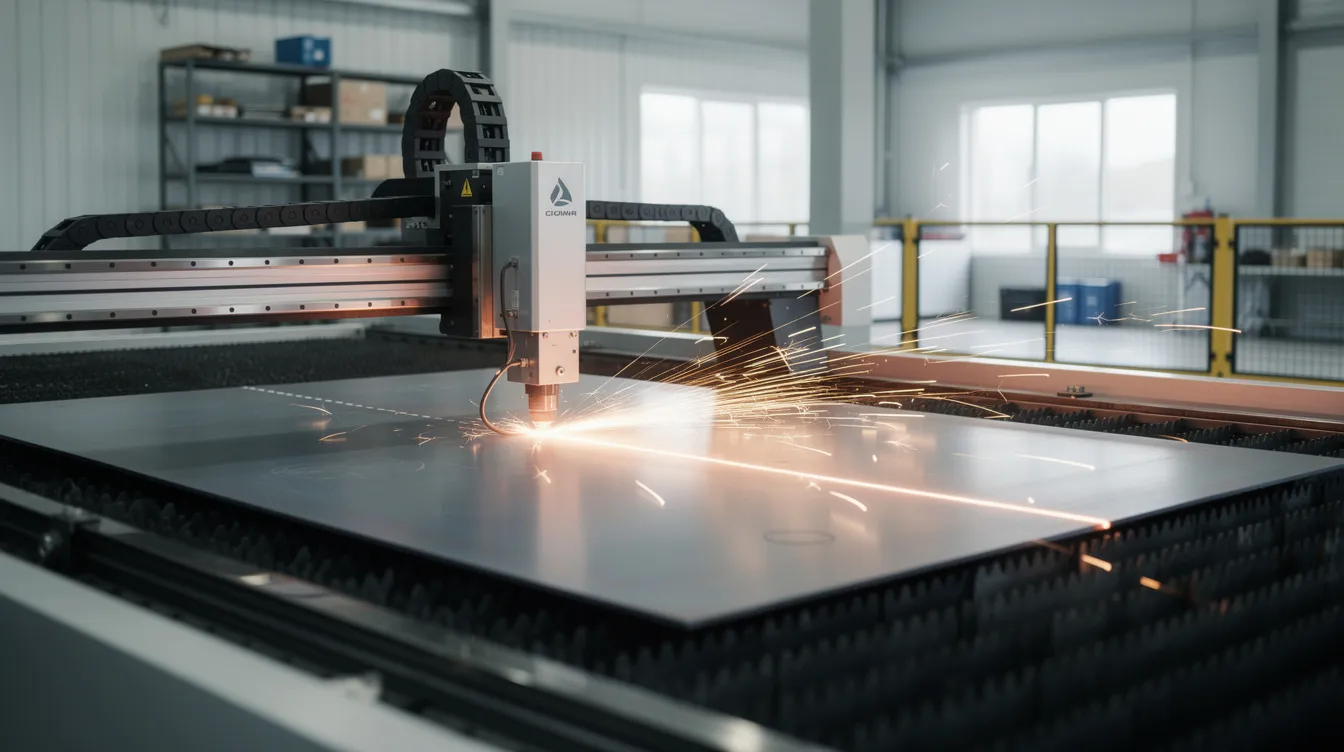
Laser cutting directly supports precise bending: tight tolerances on blanks (typically ±0.1 mm) ensure that bend lines land exactly where they should. Fiber lasers produce clean edges that minimize secondary machining, and optimized nesting algorithms reduce waste and improve material utilization.
Here is a typical process for a 3 mm cold-rolled steel enclosure:
-
CAD review and DFM – engineering reviews the 3D model for bend radius feasibility, feature placement, and material selection.
-
Flat pattern development – bend allowance and bend deduction values are applied using the correct k factor for the material and bending method.
-
Laser cutting – fiber laser cuts the blank with positional accuracy of ±0.1 mm on features.
-
Deburring – edges are cleaned to remove burrs that could initiate cracks during bending.
-
CNC press brake bending – air bending or bottoming on press brakes with maximum bending lengths around 3,000 mm and tonnage up to approximately 160–200 tons.
-
In-process inspection – digital angle gauges and calipers verify critical dimensions at each bend stage.
-
Surface treatment – powder coating, zinc plating, galvanizing, or passivation depending on end-use environment.
Anebon also offers CNC machining and die casting for assemblies that combine bent sheet and machined components – for example, welded assemblies where bent steel housings are mated to CNC-milled bases for rigid structural integrity.
Tolerances, Quality Control, and Repeatability for Bent Steel Sheet
Dimensional control is critical when multiple bent sheet metal parts must fit together in assemblies like medical device frames, electronics racks, or automotive sub-systems. A misaligned bend angle or incorrect flat pattern means parts that will not mate correctly.
-
Typical tolerances – Anebon holds linear tolerances of approximately ±0.15–0.3 mm on features after bending (depending on part size) and bend angle tolerance around ±0.5° for standard parts. Tighter specs are achievable with prior agreement, specialized tooling, and additional inspection steps.
-
First-article inspection – flat blanks are verified for cut dimensions and feature locations before bending begins.
-
In-process angle checks – digital protractors and go/no-go gauges confirm each bend angle during the bending process. For critical dimensions, a coordinate measuring machine (CMM) is used.
-
Springback compensation – Anebon programs over-bend angles into the CNC press brake using material-specific setups. Different programs handle cold-rolled steel, stainless steel, aluminum, and high strength materials, because springback occurs when metals regain shape after bending at different rates for each alloy.
-
Traceability and documentation – material certifications (mill test reports, heat numbers), process records (machine, operator, die), and the capability to provide PPAP or FAI reports are standard for regulated industries. This delivers consistent results across production batches.
-
Sampling and SPC – for larger batches, statistical process control and sampling plans ensure that bent parts maintain quality throughout the run, not just on the first article.
Choosing the Right Steel and Thickness for Bent Parts
Selecting the right material and sheet thickness is one of the earliest and most impactful decisions in a bent steel sheet project. The k factor estimates material stretch during bending differently for each grade, and forming behavior varies significantly across steel types.
-
Cold-rolled mild steel (CRS) – excellent surface finish, tight thickness tolerances, good ductility. Ideal for precise enclosures, brackets, and bent accurately held parts. Most common for electronics and machinery clients.
-
Hot-rolled steel – lower cost, less dimensional flatness, suitable for heavy structural brackets and machine bases where surface finish is secondary.
-
Stainless steel (304, 316) – for corrosion resistance, sanitary environments, or medical applications. 304 is widely used; 316 for chloride exposure. Stainless has more springback risk and may need polishing. Anebon’s thickness selection guide covers the balance between bend radius and load-bearing capacity.
-
Galvanized steel – pre-coated for corrosion resistance. Bending may crack the zinc layer unless the radius and tooling are chosen carefully to avoid coating damage.
Common thickness ranges in 2024–2026 OEM projects: 1.0 mm, 1.5 mm, 2.0 mm, 3.0 mm, and 4.0 mm for mild steel and stainless steel. Practical scenarios include choosing 2 mm galvanized steel for an outdoor electrical box versus 1.2 mm stainless for a medical device cover.
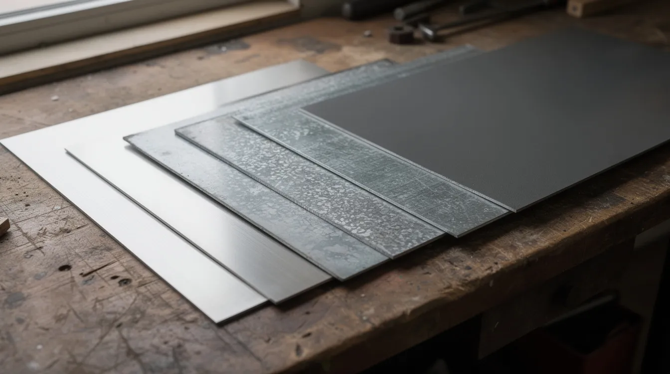
Thinner sheets (0.8–1.5 mm) allow tighter bends and finer features but may deform near holes under load. Thicker materials (4–8 mm) require larger bend radii, stronger tooling, and more force. Designers should involve Anebon early to balance material selection, bend radius, and cost – especially when switching from machined blocks to bend sheet metal for weight and cost reduction.
Cost Drivers and Lead Time for Bent Steel Sheet Parts
Sheet metal bending is generally a cost-effective near-net-shape process, but several factors drive the final price and schedule.
Primary cost drivers:
-
Number of bends – more bends per part mean more setups, tool changes, and cycle time. A simple 2-bend bracket costs significantly less than a complex 8-bend chassis with tight tolerances.
-
Special tooling – non-standard punch or die shapes, unusual bend radii, or custom v die blocks increase setup cost.
-
Material grade and thickness – stainless steel and high strength materials cost more in both raw material and processing (higher tonnage, more springback compensation). Thicker materials require more energy and slower cycle times.
-
Secondary operations – welding, machining, and surface finishing (powder coating, zinc plating, galvanizing) each add time and cost.
-
Tight tolerances – demanding linear or angular specs increase inspection frequency, trial bending, and potential scrap.
How to reduce cost:
-
Standardize on common bend radii, standard angles (90°, 135°), and uniform thickness across parts.
-
Use in house standard punch and die sets rather than custom tooling.
-
Optimize nesting for laser cutting to reduce waste on larger panels (2–3 m long).
Lead time: Anebon typically turns around simple bent steel sheet prototypes in 5–10 working days after order confirmation. Production runs depend on volume, complexity, and surface treatments, with typical ranges of 2–6 weeks for larger batches. Cold bending is performed at room temperature for high accuracy and fast cycle times, which helps keep lead times competitive.
Working with Anebon Metal Products for Bent Steel Sheet Projects
Anebon Metal Products Limited is a long-term B2B manufacturing partner founded in 2010 in Dongguan, focused on overseas OEMs needing precision bent sheet metal parts and assemblies.
-
Engagement process – begins with an NDA and drawing review, followed by DFM feedback on bend radius, grain direction, feature placement, and surface treatment recommendations. Iterative prototyping refines the design before scale-up to volume production.
-
Integrated capabilities – CNC press brakes, fiber laser cutting, CNC machining, die casting, welding, and assembly allow Anebon to deliver complete, ready-to-assemble units – not just single bent parts.
-
Quality and certification – ISO 9001:2015 for quality management and ISO 14001:2015 for environmental management. Experience meeting industry standards for automotive, medical devices, aerospace brackets, and electronics across Europe, North America, and other markets.
-
What to send – 3D models (STEP/IGES) and 2D drawings with clear bend notes: bend direction, inside bend radius, material spec, grain direction if critical, and which dimensions are functionally critical. This speeds up quoting and reduces design iterations.
Anebon works with design engineers and R&D teams from concept through production, helping to bend metal into components that meet both functional and economic requirements.
Requesting a Quote and Getting DFM Feedback
The fastest way to validate a bent steel sheet design is to get expert feedback based on real manufacturing constraints.
What to include for a precise quote:
-
3D CAD file in a neutral format (STEP or IGES) showing all bends and geometry.
-
2D drawings with bend callouts: bend angle, inside bend radius, material type and thickness, surface finish requirements.
-
Material grade (cold-rolled steel, stainless 304/316, galvanized), temper condition, and any grain direction requirements.
-
Quantity (prototypes vs. production), target delivery date, and any regulatory requirements (PPAP, FAI).
-
Clear specification of which tolerances are critical and which can be relaxed to optimize cost.
What you get back:
-
Anebon’s engineering team provides DFM suggestions on bend radius, bend sequence, hole positions near bends, and feasible tolerances.
-
While there is no generic instant pricing tool on the website, the team responds quickly – typically within 24–48 hours on working days – with cost estimates, lead times, and possible optimizations like standardizing radii, adjusting hole distances, or recommending alternate materials to achieve better part quality at lower cost.
Whether you need a single prototype or thousands of production parts, Anebon’s in house capabilities cover every step from flat blank to finished bent part.
Submit your next bent steel sheet project for review. Send your 3D model and 2D drawings with bend callouts to Anebon’s engineering team and get DFM feedback that ensures your parts are bent accurately, delivered on time, and manufactured at a competitive price point for your original shape and functional requirements.