Understanding the Numerical Control Machine: Types and Applications
Numerical Control Machine: From Classic NC to Modern Computer Numerical Control CNC
Every precision metal part starts with a command. Whether it’s an aerospace bracket, a medical implant, or an electronic enclosure, the path from raw materials to finished component runs through a numerical control machine. This guide covers the full evolution of NC technology, how CNC machines work, what separates legacy systems from modern ones, and how to select the right equipment for your production needs.
Overview: What Is a Numerical Control Machine Today?
A numerical control machine is any machine tool whose movements are governed by coded numerical instructions rather than manual handwheels or mechanical controls. Instead of an operator physically guiding a cutting tool across a workpiece, the machine follows digital instructions that dictate every axis movement, spindle speed, and feed rate with repeatable accuracy.
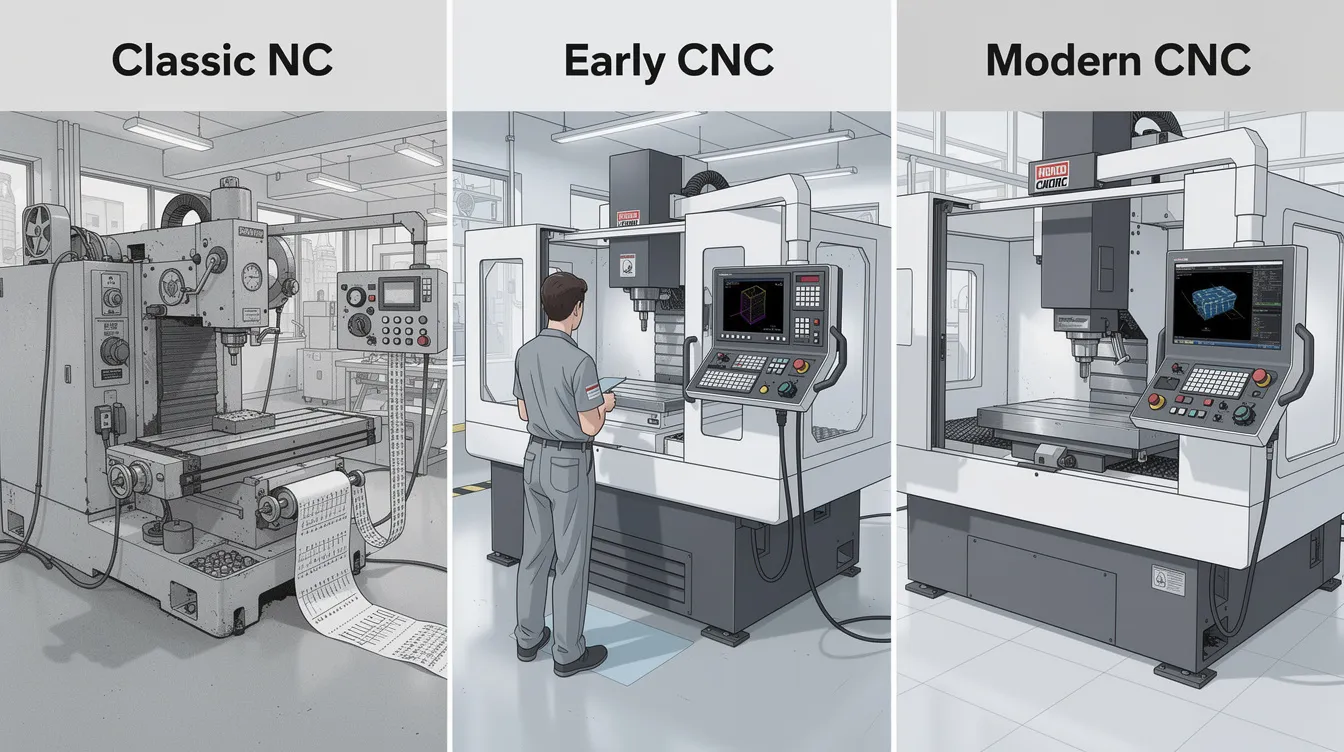
The distinction between legacy numerical control and modern computer numerical control CNC is significant. Early NC machines relied on punched tape or hard-wired logic to execute fixed programs. Editing meant physically cutting and splicing tape. Today’s CNC machines use microprocessor-based controllers that store programs digitally, accept edits on the fly, and integrate directly with computer aided design and cam software workflows.
Typical CNC machines today include machining centers, CNC milling machines, CNC lathes, grinders, EDM systems, and laser or waterjet cutters. These machines matter because they deliver tight tolerances (as precise as ±0.002 mm on critical features), surface finishes measured in fractions of a micrometer, and batch-to-batch consistency that manual operation simply cannot match. At Anebon Metal Products Limited, we leverage this technology daily as an ISO-certified CNC machining, die casting, and sheet metal partner serving overseas OEMs across the manufacturing industry.
Definition: Numerical Control vs Computer Numerical Control
Numerical control is the automated control of machine tools by precisely programmed commands encoded as numbers, letters, and symbols. At its core, the concept is straightforward: replace manual operation with machine instructions that a controller executes step by step.
NC machines in their original form used punched tapes for programming. Programs were fixed on physical media, editing was cumbersome, and controllers relied on hard-wired logic with limited flexibility. NC machines are limited to simpler tasks and operations, typically point-to-point work like repetitive drilling patterns.
Computer numerical control CNC is NC implemented via a computer that stores, edits, and executes programs digitally. CNC systems interpret g code and m codes generated from CAD/CAM data to control machine tools across multiple axes, managing spindle speed, feed rate, tool changes, and auxiliary functions simultaneously. CNC machines can be easily reprogrammed without physical changes, making them the dominant form of numerical control in modern manufacturing.
Here’s a quick comparison:
|
Factor |
NC (Legacy) |
CNC (Modern) |
|---|---|---|
|
Program storage |
Punched tape, cards |
Digital memory / files |
|
Programming |
Fixed, hard to edit |
Flexible, parametric |
|
Feedback |
Often open-loop |
Closed loop systems standard |
|
Integration |
Stand-alone |
CAD/CAM, DNC, Industry 4.0 |
|
Part complexity |
Simple, repetitive |
Complex geometries, multi-axis |
G codes and M codes in plain language: G codes are preparatory commands that tell the machine how to move-linear cuts, arcs, coordinate modes. M codes handle everything else-turning the spindle on, activating coolant, triggering a tool change, stopping the program.
Brief History: From NC Origins to CNC Machines Today
The story of numerically controlled machine tools begins in the late 1940s. John T. Parsons, working with MIT under U.S. Air Force contract, conceived of encoding milling paths as numerical data for aircraft components. By 1949–1950, Parsons developed the “Card-a-matic” concept, and MIT built prototypes based on a modified Cincinnati Hydro-Tel milling machine. In 1952, Parsons filed his foundational patent for motor-controlled machine positioning.
Through the 1950s and 1960s, NC machines proliferated in aerospace and defense. Punched tape remained the primary programming medium, and machines were expensive enough to limit adoption to large firms. The RS-274 standard for g code was published in 1963, establishing a common programming language.
The real transformation came in the 1970s and 1980s. Microprocessors and cheaper digital memory made CNC technology economically viable for a wider range of shops. Controllers evolved from hard-wired logic to embedded computers capable of storing programs, running simulations, and interfacing with CAD/CAM. Multi-axis CNC machines (3, 4, and 5-axis) became increasingly common.
From the 1990s onward, the manufacturing process accelerated: DNC networks connected shop floors, 5-axis machining enabled single-setup freeform surfacing, and hybrid additive-subtractive machines emerged. Today’s trends include AI-assisted process monitoring, digital twins, Industry 4.0 connectivity, and ultra-precision machining at sub-micron scales. ISO 6983 (finalized 1982) still underpins most g code, though newer initiatives like STEP-NC aim to embed richer manufacturing data directly into part programs.
Core Components of a Numerical Control Machine
Every numerical control machine, whether a legacy NC unit or a modern CNC system, shares a set of physical and electronic building blocks. Understanding these components helps engineers specify the right equipment and communicate effectively with manufacturing partners.
Essential components include:
-
Machine tool structure: The bed, columns, spindle, tool holders, table, and workholding clamps that form the mechanical framework-whether it’s a lathe, mill, or machining center.
-
Control system: The NC unit or CNC controller that reads the computer program, interprets commands, and sends motion signals to the drive system.
-
Drive system: Servo motors or stepper motors and their power amplifiers that physically move each axis. Servo motors provide closed-loop precision; steppers are simpler but less accurate under load.
-
Feedback devices: Encoders, resolvers, and linear scales that measure actual axis positions and report them back to the controller for real-time correction.
-
Input/output interfaces: Connections for tool change signals, coolant control, probing, spindle monitoring, and safety interlocks. A computer interface allows program upload and networked operation.
The control system interprets g code into coordinated axis movement within a 3D Cartesian coordinate system (X, Y, Z), plus rotary axes (A, B, C) where applicable. In open-loop systems, the controller sends commands assuming they are followed correctly-errors accumulate. In closed loop systems, feedback devices continuously compare actual versus commanded position, and the controller corrects deviations in real time. For high precision metalworking, closed-loop control is non-negotiable.
Mechanical precision is limited by physical realities: backlash in screws, thermal expansion, and structural deflection. Modern machines mitigate these with ball screws, linear guides, preloaded bearings, and compensation tables for backlash, pitch error, and temperature drift.
Ancillary systems found in CNC machines today include automatic tool changers (storing dozens of multiple tools), coolant systems (flood, mist, high-pressure), touch probes for workpiece alignment and measurement, and safety enclosures to contain chips and protect operators.
Control System and CNC Language (G Codes and Beyond)
The control system is the “brain” of a numerical control machine, executing numerical instructions in real time to coordinate every aspect of the machining process.
G code commands specific movements of CNC machines. These standardized preparatory functions control linear moves (G01), rapid positioning (G00), circular interpolation (G02/G03), coordinate modes (G90 absolute, G91 incremental), tool radius compensation, and work offsets (G54–G59). CNC programming uses g code for tool speed and feed rate, making it the universal language of computerized numerical control.
M codes are used for miscellaneous machine commands in CNC: spindle start (M03/M04), spindle stop (M05), coolant on/off (M08/M09), tool change (M06), and program end (M30). Together, g and m codes give the controller complete authority over desired operations.
Modern CNC systems also support macro programming, parametric variables, canned cycles (drilling, tapping, pocketing), and sub-program calls. These features reduce code complexity and enable automatic programming of recurring part families.
Standards like ISO 6983 historically defined g code structure. Newer initiatives like STEP-NC aim to embed geometry, tolerances, and material data directly into the programming model.
CNC programs often start with a percent symbol and program number. Here’s an annotated example:
%
O1001                         ; Program numbe
N100 G90 G54 X0 Y0 Z5.0      ; Absolute mode, work offset, start position
N110 G01 Z-10.0 F200         ; Linear feed into material at 200 mm/min
N120 G01 X50.0 Y0 F400       ; Cut along X at 400 mm/min
N130 G02 X50.0 Y50.0 R25 F400 ; Clockwise arc to Y50, radius 25
N140 G01 Z5.0                ; Retract tool
N150 M05                     ; Spindle stop
N160 M30                     ; End program
%
How Numerical Control Machines Work: From CAD to Finished Part
The digital workflow that drives CNC machines today connects design intent to physical reality through a series of well-defined stages. Each step translates abstract geometry into actual machining.
The production process follows this flow:
-
CAD design: Engineers define part geometry in software like SolidWorks, CATIA, or Fusion 360.
-
CAM toolpath generation: Cam software converts the 3D model into cutting strategies-roughing, semi-finishing, finishing-optimized for tool engagement, chip load, and surface quality. CNC programming can be generated from CAD designs, dramatically reducing manual programming effort.
-
Post-processing: The CAM system outputs machine-specific g code adapted to the controller’s syntax, axis configuration, and tool numbering.
-
Program transfer: Code is sent to the CNC control system via USB, network, or DNC streaming.
-
Setup: Operators secure the workpiece, align fixtures, calibrate tools, and set work offsets.
-
Test run: A dry run or simulation verifies clearances and catches potential collisions before actual machining begins.
-
Production: The machine executes the program. Sensors monitor tool wear, thermal conditions, and cutting forces.
-
Inspection and quality control: Finished parts are measured using calipers, micrometers, CMMs, or in-process probing against GD&T specifications.
Cam software is where most of the intelligence lives. It automatically generates optimized toolpaths, simulates tool motion to prevent crashes, recognizes features (holes, pockets, contours), and stores template processes for recurring part families. This replaces the tedious manual calculation that traditional NC programming required.
CNC machines work in multiple axes by interpolating simultaneous motion across X, Y, Z, and rotary axes to cut complex shapes in a single setup. Feedback systems confirm position via encoders, while load sensors can trigger alarms or adjust feed when conditions change. Closed loop systems correct deviations in real time, maintaining machining accuracy throughout the run.
Tool and machine crashing remains a real risk. Common causes include programming errors, fixture misalignment, and incorrect tool lengths. Mitigation strategies include simulation software verification, soft limits on axis travel, probing cycles before cuts, and operator training.
Positioning Control, Cartesian Coordinates and Accuracy
Every tool position and orientation in a CNC machine is defined using Cartesian coordinates (X, Y, Z) plus rotary axes (A, B, C) for machines with tilting or rotating capability. The controller uses these coordinates to calculate every movement the servo motors must execute.
Absolute coordinates (G90) reference all positions to a fixed work zero. Incremental coordinates (G91) reference each move to the previous position. CNC work offset systems (G54–G59) allow operators to define multiple part setups on one table-each with its own “work zero” relative to the machine’s home position (“machine zero”).
Positioning control uses servo or stepper motors to drive each axis following commanded positions, velocities, and accelerations. In practice, numerical precision meets mechanical reality: backlash in lead screws, thermal expansion of the spindle and frame, and tool deflection all introduce error. CNC controls compensate by applying backlash compensation tables and pitch error maps calibrated from linear scale feedback.
Typical tolerances for precision machining: ±0.05 mm for general features, ±0.01 mm for precision work, and down to ±0.002 mm for critical dimensions. CNC systems can achieve accuracy down to one-hundredth of a millimeter, and CNC machines ensure high precision down to one-hundredth of a millimeter across production batches. Surface roughness ranges from Ra 1.6 µm (standard machining) to Ra 0.4 µm or lower with grinding and polishing.
Types of Numerical Control Machines and CNC Systems
Numerical control machines are categorized by both machine type and control strategy. The right choice depends on part geometry, material, tolerance requirements, and production volume.
Main machine categories include:
-
CNC milling machines and machining centers
-
CNC lathes and turning centers
-
CNC grinding machines
-
EDM machines (wire and sinker)
-
CNC laser cutters and waterjet cutters
-
Plasma cutters
-
CNC routers
Control strategies divide into point-to-point (drilling, punching-tool moves to position, performs operation, moves again) and contouring (milling, profiling-axes move simultaneously to follow a continuous path). CNC systems support complex multi-axis operations, and modern metalcutting CNC systems are virtually always closed-loop for accuracy. Adaptive control systems can even adjust feeds and speeds based on sensor input during the cut.
CNC Milling Machines and Machining Centers
CNC milling machines move a rotating cutting tool relative to a stationary or repositioned workpiece along multiple axes. CNC milling machines can produce highly complex geometries, including pockets, slots, contours, and freeform surfaces.
Vertical machining centers (VMCs) orient the spindle vertically-ideal for prismatic parts and accessible tool changes. Horizontal machining centers (HMCs) orient the spindle horizontally, providing better chip evacuation and access to multiple workpiece faces.
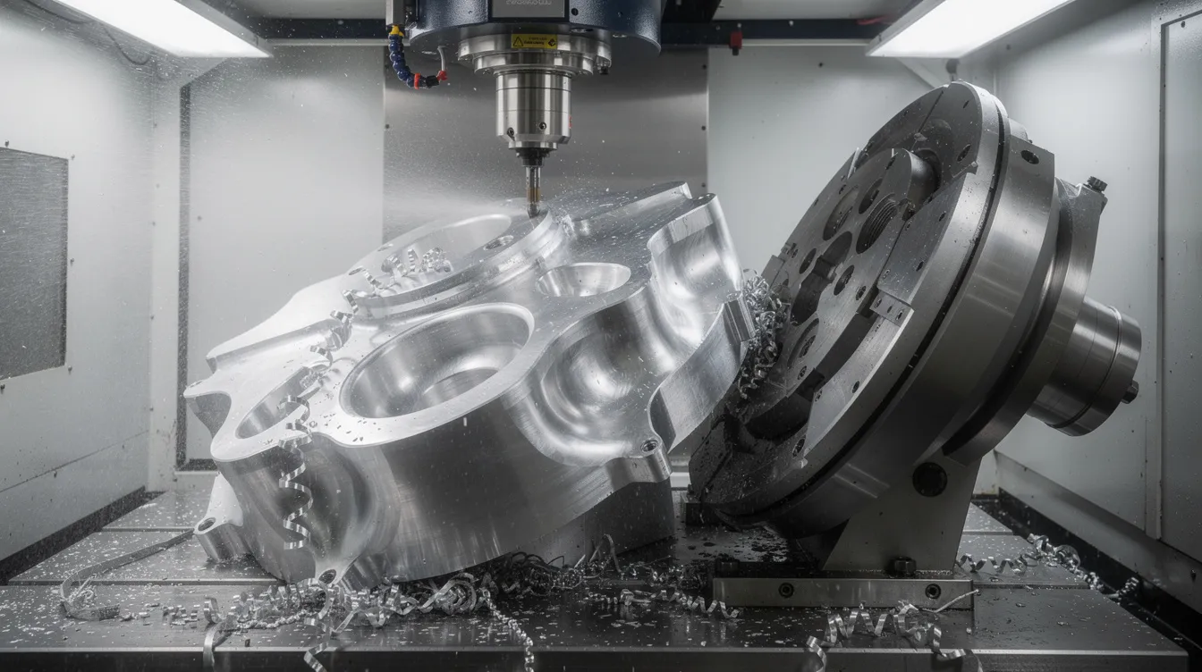
5-axis CNC machines tilt and rotate the workpiece or head, enabling complex freeform surfaces like turbine blades and orthopedic implants to be machined in one setup. CNC machines can operate on multiple axes, including 3, 4, or 5 axes, and can handle complex multi-dimensional curves and geometries accurately. Automatic tool changers and tool magazines enable machining centers to perform complex machining tasks-drilling, reaming, tapping, pocketing, and contouring-without manual intervention.
CNC Lathes and Turning Centers
CNC lathes are numerical control machines that rotate the workpiece while stationary tools perform turning, facing, threading, and grooving. CNC lathes perform complex tasks like threading and contouring with repeatability that manual lathes cannot match.
Turning centers extend this capability with live tooling (rotating tools mounted on the turret), Y-axis for off-center milling, and sub-spindles for back-working operations. This allows multiple operations-milling, drilling, tapping-in a single setup on one machine.
Typical turned components include shafts, bushings, connectors, fasteners, and medical bone screws requiring tight concentricity and surface finish. For precision turned components in aluminum and other alloys, Anebon’s CNC turning services deliver the tolerances and finish quality that demanding applications require.
Other CNC Machines: Grinding, EDM, Laser and Hybrid Systems
CNC grinders achieve micrometer-level tolerances and high-quality surface finishes on hardened steel tools and precision components. CNC grinders can work in micrometers for high precision, making them essential for bearing surfaces, gauge blocks, and finishing operations where surface integrity is critical.
Sinker EDM and wire EDM are numerical control machines that use electrical discharges to shape conductive materials with minimal cutting forces. They excel at cutting complex parts in hardened tool steels and carbides where conventional cutting tools would fail.
CNC laser cutters use focused lasers for precise cutting of sheet metal and plate, producing clean edges with minimal heat-affected zones. CNC waterjet cutters add the advantage of zero thermal distortion, making them ideal for heat-sensitive materials.
CNC routers are ideal for cutting softer materials like wood, plastics, and composites, and are widely used in sign-making, furniture, and composite aerospace panels.
Emerging hybrid machines combine additive manufacturing (metal 3D printing) and CNC machining in one enclosure, enabling near-net-shape builds followed by precision finishing-reducing both lead time and material waste.
Applications: How CNC Machines Work in Real Industries
Numerical control machines power modern production across various industries: aerospace, automotive, medical devices, electronics, robotics, and industrial machinery. The common thread is a need to perform complex and precise operations at scale with documented, traceable quality.
Concrete examples include:
-
Aerospace: Turbine blades, structural brackets, impellers, and transmission components requiring ±0.002–0.005 mm tolerances and complex shapes machined from titanium and superalloys.
-
Medical: Orthopedic implants, surgical instruments, and dental components produced under medical device manufacturing standards with full traceability. Tolerances often reach ±0.0127–0.05 mm under ISO 13485 requirements.
-
Automotive: Engine blocks, gearbox housings, fuel injectors, and transmission components demanding tight surface finish and mass production repeatability.
-
Electronics: Smartphone frames, electronic enclosures, connectors, and heatsinks with fine features and complex geometries. Anebon’s electronics manufacturing capabilities address these needs directly.
-
Robotics & industrial machinery: Precision joints, actuator housings, and sensor mounts where dimensional accuracy governs assembly fit.
CNC machining supports both rapid prototyping (single to tens of parts) and full production (hundreds to thousands) with the same equipment-you change the computer program and fixtures, not the machine. CNC machining allows for automated, consistent production of complex parts regardless of batch size.
CNC also plays a critical role in mold and die making, where machining accuracy and surface finish directly determine the quality of downstream injection molding and die casting tools.
Benefits of Computer Numerical Control in Production
CNC technology delivers measurable advantages over both manual machining and legacy NC systems:
-
Precision and repeatability: CNC machines offer higher precision and accuracy than NC machines. Production batches targeting Cpk ≥1.33 ensure dimensional consistency across thousands of parts.
-
Complexity without compromise: Modern machines can perform complex machining operations-multi-axis contouring, undercuts, deep cavities-that would be impossible with manual operation.
-
Speed and automation: CNC machines can operate continuously reducing labor costs and production time. CNC technology allows for mass production with minimal supervision, enabling lights-out manufacturing where machines run unattended.
-
Reduced waste: CNC machines reduce material waste through optimized toolpaths that cam software calculates for maximum material efficiency.
-
Lower error rates: CNC machining reduces human error and increases production efficiency. Stored work offsets, tool data, macros, and reusable programs eliminate setup variability.
-
Easy changeovers: CNC machines enhance automation, reducing manual labor requirements. Changeovers require loading a new program and adjusting fixtures-not rebuilding the machine.
For OEM customers, these benefits translate directly into consistent quality across batches, easier design revisions (just update the CAD model and regenerate toolpaths), improved traceability through digital documentation, and lower production costs at scale.
NC vs CNC: Direct Comparison and When Each Still Matters
While CNC systems dominate modern manufacturing, some classic NC or early CNC machines still operate in shops where complex tasks aren’t required and programs remain stable for years.
NC machines typically use punched tape, have limited program editing capability, and are best suited for repetitive point-to-point operations like drilling fixed hole patterns. Their control is often open-loop, and integrating them with modern CAD/CAM workflows is impractical.
CNC machines store programs digitally, integrate with CAD and cam software, allow fast edits, and support complex contouring and multi-axis operations. CNC machines can be reprogrammed for different production tasks easily, and can adapt to new projects by changing programs easily-a flexibility that legacy nc machines simply cannot match. CNC machines operate using g code for precise movements, enabling the controller to automate machine tools with minimal human intervention across the entire production process.
CNC systems enable higher automation with robotics, pallet systems, and lights-out manufacturing, which are impractical on traditional NC hardware. The cost of ownership equation favors CNC: higher upfront investment, but dramatically lower per-part cost, scrap rate, and changeover time.
Key takeaway: CNC is the practical choice for almost all new investments. Legacy NC equipment may still serve niche roles, but for any operation requiring flexibility, complexity, or integration with digital workflows, computer control via CNC is the clear path forward.
Programming, CAM Software and Digital Workflow
Traditional NC programming involved manual calculation of toolpaths and direct code entry-a skilled but slow and error-prone process. Manual programming is still useful for simple operations, but modern CNC programs are generated primarily through cam software.
Cam software automatically generates optimized toolpaths and g code from CAD models, reducing human error and programming time. Practical features include simulation software to verify cuts and avoid crashes, automatic feature recognition for holes and pockets, and template processes for recurring part families.
DNC (direct numerical control) and networked nc systems store programs centrally and stream them to many CNC machines across a shop floor. This eliminates version-control issues and enables centralized process management-a key element of the digital manufacturing process in any modern facility.
Challenges, Limitations and Best Practices in Using CNC Systems
Numerical control machines require proper planning, maintenance, and skilled operation to reach their full potential. Even the best CNC technology cannot compensate for poor process discipline.
Common challenges include:
-
Programming errors: Programming errors in CNC operations can lead to defective part production. Verification through simulation software before actual machining is essential.
-
Setup mistakes: Misaligned fixtures, incorrect tool offsets, and wrong work zeros cause scrap and potential machine crashes.
-
Tool wear: Unmonitored tool degradation leads to dimensional drift and poor surface finish.
-
Thermal drift: Temperature changes in the machine, environment, and workpiece shift dimensions over long runs.
-
Investment costs: CNC machines require significant upfront investments compared to manual machinery, and CNC machines necessitate specialized programming skills for setup and maintenance.
Best practices for process stability:
-
Calibrate spindle runout, ballscrew backlash, and axis alignment on a regular schedule
-
Run first-article inspections and in-process probing on every new job
-
Use CMMs and documented quality control procedures aligned with ISO 9001:2015
-
Train operators on control system interfaces, g code fundamentals, CAM workflows, and basic metrology
-
Maintain coolant systems, replace worn tools proactively, and monitor thermal variation throughout shifts
Choosing the Right Numerical Control Machine for Your Application
Selecting CNC machines is a strategic decision that balances part geometry, material, tolerances, production volumes, and budget.
Key evaluation factors:
-
Required axes and travels: 3-axis VMC for prismatic metal parts, 5-axis for complex surfaces, turning centers for rotational parts
-
Spindle power and speed: Dictated by material-aluminum demands high RPM, titanium needs high torque
-
Control system capabilities: Macro support, probing integration, network connectivity
-
Accuracy and repeatability specs: Match to your tightest tolerance requirements
-
Automation options: Pallet changers, robotic loading, bar feeders for volume work
Matching machine type to work: a 3-axis VMC handles most prismatic sheet metal and plate components, 5-axis machining tackles complex surfaces and undercuts, turning centers address rotational parts, and specialized machines handle grinding or EDM where standard cutting tools fall short.
Engaging a manufacturing partner early helps optimize the entire production process. Design for manufacturability (DFM) feedback can determine whether CNC machining, die casting, or sheet metal fabrication offers the best cost-to-quality ratio for your specific part.
Anebon’s Perspective: Leveraging CNC Technology for OEM Manufacturing
Anebon Metal Products Limited has operated as a precision CNC machining, die casting, and sheet metal fabrication provider since 2010, headquartered in Dongguan, China. We built our business around a straightforward principle: deliver the precision, consistency, and communication that overseas OEMs demand.
Our capabilities span multi-axis CNC milling, CNC turning, 5-axis machining, and precision grinding, with tolerances as tight as ±0.002 mm on critical features. We work across a wide material range-aluminum, titanium, stainless steels, copper alloys, and engineering plastics-and apply surface treatments (anodizing, plating, coatings) in-house.
We hold ISO 9001:2015 and ISO 14001:2015 certifications, reflecting our commitment to quality assurance and environmental responsibility. Our typical customers are overseas OEMs, design engineers, and R&D teams in aerospace, medical devices, automotive, electronics, robotics, and industrial machinery.
Our service model covers the full arc: rapid prototyping for design validation, bridge tooling to fill the gap before mass production tooling is ready, and full-scale production with DFM consulting, CAM programming, and quality control under one roof. Whether you need a single prototype or tens of thousands of production parts, we scale to your needs.
Ready to get started? Upload your CAD files for a fast, engineering-driven quotation. Our team reviews geometry, materials, and tolerances to recommend the most cost-effective manufacturing process for your project-whether that’s precision CNC machining, die casting, or sheet metal fabrication.