Understanding the Joggle: Essential Techniques for Sheet Metalworking
Joggle: Definition, Sheet Metal Applications & Manufacturing Guide
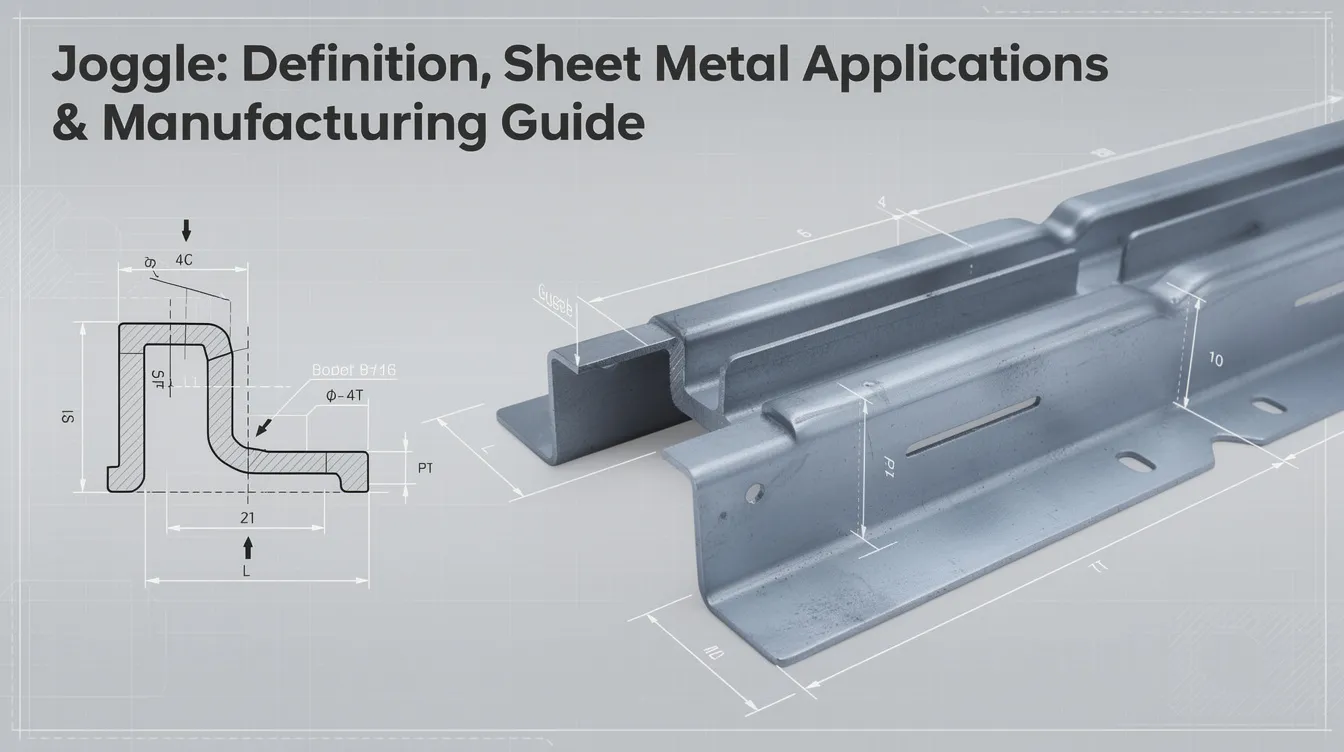
A joggle is one of those terms that pulls double duty in English. In everyday language it means to shake slightly or jostle. In sheet metal fabrication, the word refers to a precise, Z-shaped offset bend that lets overlapping panels share a flush surface. This guide will walk you through both meanings, then dive deep into how joggles are designed, formed, and applied across industries.
What is a Joggle? (Answer the Query Fast)
To define joggle in the simplest way: as a verb, it means to jog or shake something with small, repeated motions-rocking it to and fro. As a noun in metalworking, a joggle is a small offset or step created near the edge of a sheet so two pieces can overlap without a visible bump on the outside.
-
A joggle creates a Z-shaped bend in sheet metal, displacing one plane relative to another by roughly the thickness of the mating sheet.
-
Joggle bends are typically less than 90 degrees-often between 30° and 60° per bend.
-
The term is called an offset bend or step bend interchangeably in engineering, though “joggle” implies a relatively small offset.
-
Joggles are used in aircraft and automotive sheet metal work, as well as enclosure covers and structural panels.
-
The first known use of “joggle” was in 1513, derived from the word jog.
-
Pronunciation: /ˈdʒɒɡl/ (“JOG-uhl”).
General Meanings of “Joggle” in English
Before focusing on metalworking, it helps to understand the broader meaning of this term.
-
As a verb, “joggle” means to move unsteadily or shake slightly-to jostle with repeated small jerks. Example: “The train joggled the passengers as it crossed the old bridge.” The verb form has been used in the context of movement since at least 1820.
-
The past participle “joggled” appears commonly: “He joggled the handle until the stuck drawer gave way.”
-
As a noun, it describes a slight push or irregular movement. The noun form of “joggle” was first used around 1727.
-
In stonemasonry, a joggle joint often features a tongue-a projection-that fits into a matching groove, functioning much like a dowel to lock heavy stones together. In historic construction, joggles prevent sliding in arches or lintels.
-
In traditional boat building, joggles are notches cut into ribs to fit planks flush against the frame.
-
Beyond engineering, there is also a software platform called Joggle that integrates website, bookings, and customer communications for hospitality businesses. Joggle updates menus and events instantly across all platforms, handles bookings and deposits automatically via Stripe, and can answer customer inquiries 24/7 through multiple channels. The average small business pays £180–£500/month for disconnected tools, whereas Joggle replaces multiple subscriptions with one simple plan-though that type of joggle is a different page entirely from the one we cover here.
What is a Joggle in Sheet Metal Fabrication?
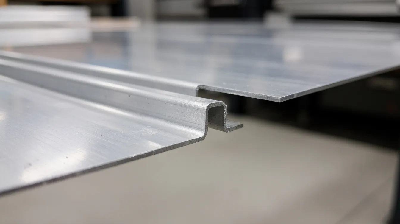
In sheet metal fabrication, a joggle is a small, Z-shaped offset bend formed close to the edge of a sheet. It allows one piece to overlap another while maintaining a flush outer joining surface.
-
Geometrically, two opposite bends in close succession create a step. Joggle dimensions depend on sheet metal thickness and required clearance-the step height typically matches or slightly exceeds the mating sheet’s thickness.
-
Joggles are used in sheet metal construction to allow two sheets to overlap without increasing overall stack height.
-
Common material types include aluminum alloys (5052, 6061), mild steel, galvanized steel, and stainless steels (304, 316).
-
Typical thickness range: approximately 0.7 mm to 3.0 mm for enclosure and panel work; thicker gauges for structural applications require heavier tooling.
-
Joggles can be produced by press brake joggle tools, dedicated joggle benders, or custom CNC-machined dies. In Anebon’s precision environment, every joggle is modeled in 3D CAD and verified through DFM review before production-no time lost waiting for trial-and-error on the shop floor.
Purpose and Functional Benefits of Joggles
The primary point of a joggle is clearance: joggle allows two surfaces to join flush in crafts and manufacturing without doubling the stack thickness at the overlap.
-
Strength: Joggles increase the structural integrity of joints in heavy machinery. They resist shear forces and lateral movement between connected members, and a joggle prevents two components from sliding or shifting past each other. Joggles create stronger, flush joints and save material in manufacturing.
-
Assembly: Self-locating joints simplify riveting, bolting, or spot welding, delivering consistent gaps and easier alignment. Flush joints are critical in aerospace and automotive applications.
-
Performance: Flush overlaps improve gasketing, adhesive bonding, and EMI shielding in electronics enclosures. In masonry, joggles lock stones together to prevent sliding-a principle that finds its parallel in metal, where the step form keeps mating sheets from shifting.
Compared to a simple lap joint, a joggle keeps the outer surface level, whereas a plain lap creates a visible step and possible interference. There is no doubt that this change in geometry pays for itself in assembly time and final fit.
Joggle Forming Process in Sheet Metal
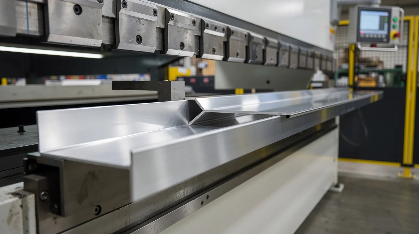
Joggle forming involves a punch and die in metal fabrication. The sheet is placed between a matched joggle punch and die set, then a CNC press brake applies force to form the Z-shaped offset-often in a single hit.
-
Select tooling with an offset height equal to or slightly greater than the mating sheet thickness.
-
Align the bend line, set the backgauge, and run a test piece before committing to production.
-
Key parameters to specify: offset height, run length (distance between bends), inside bend radius, and tolerances (commonly ±0.30 mm for offset height).
-
Equipment: CNC press brakes in the 80–160 ton class with segmented joggle tooling.
-
Stainless steel may require 50–60% more tonnage than mild steel of the same thickness. Aluminum forms more easily but cracks if the radius is too tight.
-
Minimum inside bend radius ≥ 1× sheet thickness for mild steel; slightly larger for stainless. Maintain ≥ 2× thickness from holes and edges to avoid distortion.
-
Anebon validates new setups with first-article inspection, using calipers or CMM to check offset height and angles before full production begins.
How to Make a Joggle in Sheet Metal (Practical Steps)
This is a step-by-step guide for design engineers collaborating with a fabricator-simply read through and adapt to your project.
-
Define joggle geometry in CAD – specify offset equal to mating sheet thickness, run length, bend centerline positions, and tolerances. Include callouts on 2D drawings. Designs can be edited and resubmitted as the DFM process raises questions.
-
Confirm material type and thickness – for example, 2.0 mm 5052-H32 aluminum or 3.0 mm mild steel. Document grain direction for fatigue-sensitive parts.
-
Review with manufacturer (DFM) – have Anebon’s engineers check whether the joggle can be formed in a single hit, whether special tools or multi-stage forming is required, and if reliefs are needed.
-
Tool selection and trial – choose appropriate punch and die; perform samples on scrap; measure offset height, run length, and flatness.
-
Adjust press brake parameters – fine-tune tonnage, backgauge, and bend allowance to compensate for springback, particularly on high-strength stainless or titanium.
-
Implement in production – lock down setup sheets, inspection plans, and gauge fixtures so joggles remain repeatable across batches and operators.
Applications of Joggles in Different Industries
Joggles find their place across a great range of sectors. Project owners from Mexico to Munich to Chicago rely on joggled features for cleaner assemblies.
-
Electronics enclosures: Joggled edges on doors and covers create flush overlaps that improve appearance and EMI shielding; typical materials include 1.5 mm cold-rolled steel or 2.0 mm aluminum. See sheet metal enclosure examples.
-
Aerospace and aviation: Joggled skins and stiffeners in fuselage panels and wing structures allow overlapping without aerodynamic steps. Joggling creates smooth joints without adding weight in aerospace applications.
-
Automotive and transport: Brackets, body panels, and floor assemblies use joggles where components must nest in compact spaces.
-
Construction and building material systems: Joggled steel components appear in curtain wall brackets, façade sub-frames, and roofing trims-anywhere a water-shedding overlap or clean architectural line matters. Joggles are also used to connect braces, joists, or posts to beams in timber-and-steel hybrid structures.
-
Civil and infrastructure: In reinforced concrete, steel rebar is joggled to provide secure connections at lap splices while maintaining concrete cover.
Sheet Metal Joggle Tooling and Example Project
A joggle tool set is a matched punch and die pair with a built-in offset. Lengths can reach 1,500–2,000 mm for long panels, with cross-sections sized per material thickness. Common tool steels such as 42CrMo are hardened to ~50–55 HRC to withstand repeated forming-especially against stainless steel, which causes galling on softer tools.
-
Example case: Anebon exports a 2,000 mm joggle die set (hardened steel, ~20 kg) and 50 sample joggled parts in 2.0 mm 5052-H32 aluminum to an OEM site in Chicago. Parts ship in a wooden crate with rust-preventive oil and protective wrapping. Transit from Dongguan by sea takes roughly 25–35 days. Each shipment includes a measurement report-a document confirming offset height ±0.30 mm, bend radii, and surface condition.
-
Anebon can also CNC machine custom joggle dies for non-standard offsets or unique aerospace profiles not found in catalog tooling. Think of it as the difference between buying off-the-shelf and having an in-house solution built to your exact specifications.
Design Considerations & Best Practices for Joggled Parts
If you’ve given any thought to adding joggles to your next design, these guidelines will help you avoid common pitfalls.
-
Keep edge distance from joggle to sheet edge ≥ 2–3× material thickness to prevent distortion or cracks during forming.
-
Minimum run length between bends: start at ≥ 3× thickness and refine through DFM. This gives the chance for tooling clearance and reduces thinning.
-
Avoid placing holes, slots, or cutouts directly in bend zones. Features too close to the offset step will distort.
-
Decide which surface must remain flush-outer cosmetic face vs. inner functional face-and assign tighter tolerances only where needed. This is a great way to control cost without sacrificing fit.
-
For high-precision assemblies, combine joggle forming with secondary CNC machining (reaming, countersinking) after bending.
-
Submit 3D models and drawings early. Anebon’s team replies with DFM feedback-proposing radius changes, reliefs, or alternate joint layouts-so every joggle is manufacturable at day-one production scale.
The table below summarizes key design parameters:
|
Parameter |
Guideline |
|---|---|
|
Edge distance |
≥ 2–3× material thickness |
|
Run length (between bends) |
≥ 3× material thickness |
|
Inside bend radius (mild steel) |
≥ 1× thickness |
|
Inside bend radius (stainless) |
≥ 1.2–1.5× thickness |
|
Offset height tolerance |
±0.30 mm (±0.012 in) typical |
|
Feature distance from bend |
≥ 2× thickness |
How Anebon Metal Products Limited Supports Joggle & Offset Bend Projects
Anebon is an ISO 9001:2015 and ISO 14001:2015 certified precision manufacturer based in Dongguan, Guangdong, China. Since 2010, we have served overseas OEMs who need everything from rapid prototyping to full-scale production-and joggled sheet metal parts are a core part of that experience.
-
Core capabilities: CNC press brake sheet metal fabrication, CNC machining of mating components, die casting of complementary housings, and 5-axis machining for complex joggle tooling.
-
Tolerances: As tight as ±0.002 mm in CNC machining; practical forming tolerances for joggles are defined jointly with each customer based on material and part size.
-
DFM support: Our engineers review joggle designs, suggest optimized offsets, bend radii, and material choices, and plan forming sequences to minimize distortion.
-
Downstream services: Surface treatments (anodizing, powder coating, plating), assembly of joggled sheet metal with machined or die-cast parts, and 100% inspection for safety-critical components.
-
Stay connected: Subscribe to our newsletter or visit our website to find the latest updates. For any questions, email our engineering team directly.
The joy of working with a single-source manufacturer is that nothing gets lost between departments. Send your 3D CAD files and drawings to Anebon today to request a quote for prototypes or production runs involving joggles-we look forward to helping you build something great.