Understanding the Bending of Sheet Metal: Techniques and Tips
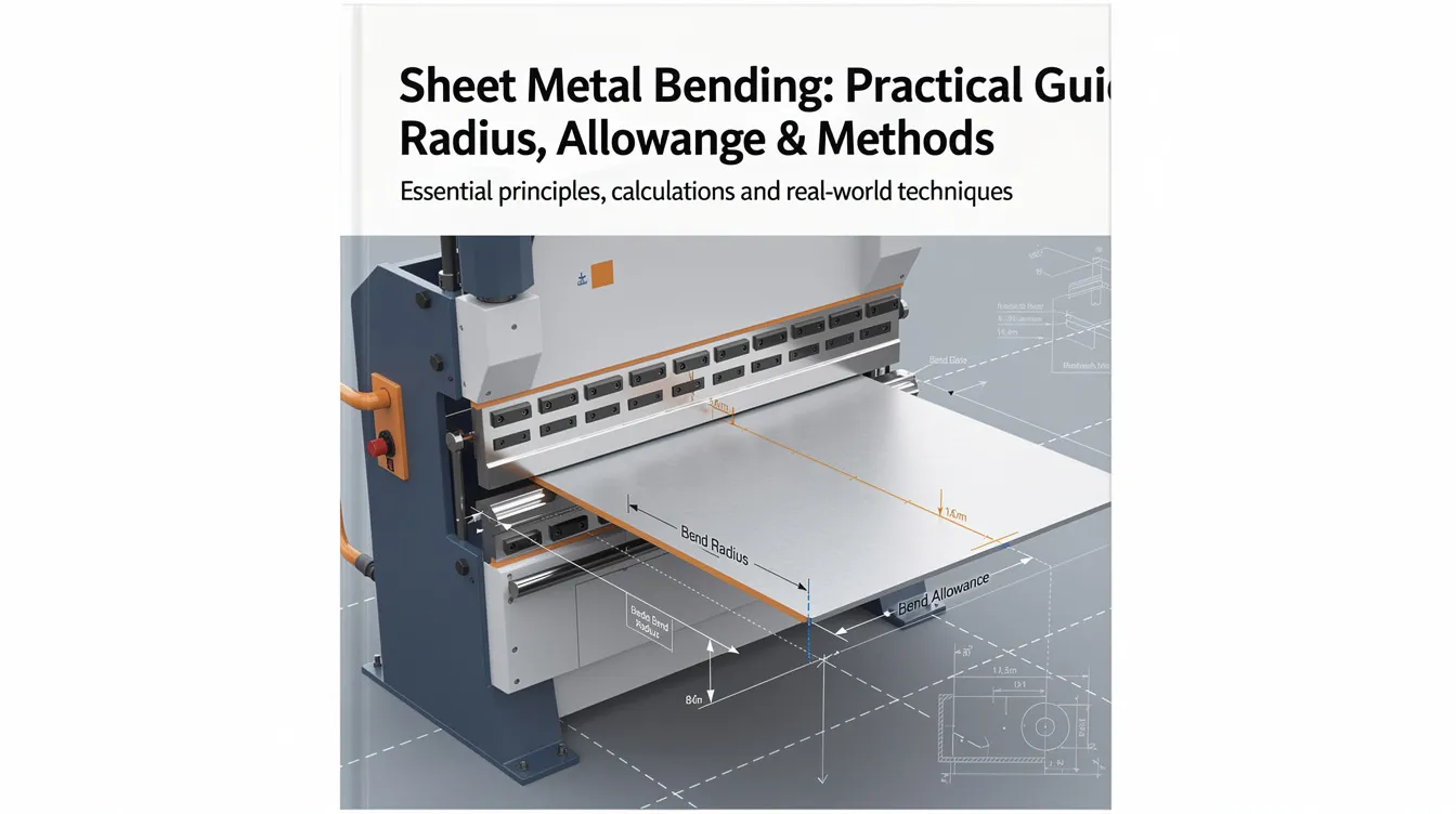
Sheet Metal Bending: Practical Guide to Radius, Allowance & Methods
Introduction to Sheet Metal Bending
Sheet metal bending is one of the most fundamental operations in modern fabrication. It uses force to deform a flat sheet into angles or curves, transforming a simple blank into a functional, three-dimensional component without removing any material. Unlike machining, which cuts away stock, or welding, which joins separate pieces with filler, the bending process reshapes the metal through controlled plastic deformation. The result is a part that retains its structural integrity, wastes less raw material, and is ready for assembly with minimal secondary work. Bending reduces part weight without needing additional materials, making it a go-to process for lightweight structural components across industries.
For design engineers and OEM buyers, understanding the mechanics behind sheet metal bending is not optional. Decisions about bend radius, bending method, bend allowance, k factor, and springback compensation directly affect whether your parts fit together, survive in service, and stay within budget. A miscalculated allowance or an overly aggressive radius can mean cracked flanges, misaligned holes, or rejected batches.
This guide covers the core concepts you need to make informed design and sourcing decisions: how bend radius and the neutral axis affect your flat pattern, how to choose between air bending, bottom bending, and coining, what material properties matter most, and how to calculate bend allowance for accurate results. Throughout the article, we’ll reference practical examples from Anebon’s own production. In our 2023 electronics enclosure program, for instance, we bent 1.2 mm thick 5052 aluminum on CNC press brakes to ±0.1 mm angular and positional tolerances, a project where getting the allowance and radius right was the difference between a perfect snap-fit assembly and a bin full of scrap.
What Is Sheet Metal Bending?
Sheet metal bending is the process of plastically deforming a metal sheet along a straight or curved bend line so that part of the cross-section stretches on the outer face while the inner face compresses. The neutral axis, a plane within the material where fibers neither stretch nor compress, shifts inward during forming. Sheet thickness stays essentially constant, with only minor thinning at the outer bend face. The deformation is permanent once the material’s yield point is exceeded.
You’ll encounter several names for this process depending on the specific technique or equipment involved: forming, folding, flanging, edging, press braking, and die bending all fall under the broader umbrella of sheet metal fabrication. Each name typically refers to a variation in tooling, clamping method, or machine type rather than a fundamentally different concept.
The press brake is the primary workhorse for most bending operations, but other bending machines include folding machines (for long flanges), roll bending equipment (for large-radius curves), and rotary benders. Machining methods for sheet metal include press brake bending, stamping, and roll forming, each suited to different geometries and volumes. Bending can be performed on materials up to 20mm thick, though most precision OEM work involves thin to medium gauge sheet.
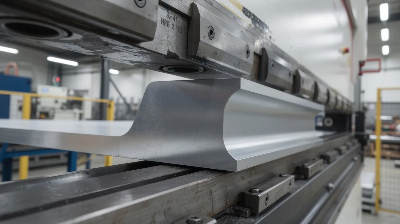
Real-world parts that rely on accurate bending include:
-
Automotive brackets: Small steel or aluminum brackets with multiple bends that provide stiff flanges for mounting engines, sensors, or body panels.
-
Medical equipment chassis: Stainless steel enclosures and frames with precise 90° bends, tight mating surfaces, and finishes that must withstand sterilization.
-
Aerospace avionics trays: Lightweight aluminum or titanium trays with tight bend radii, corrosion resistance, and precision mounting features for sensitive electronics.
Key characteristics of the sheet metal bending process:
-
Permanent plastic deformation without material removal.
-
The neutral axis shifts inward from its theoretical mid-thickness position during forming.
-
Outer fibers stretch, inner fibers compress; excessive strain causes cracking.
-
Springback (elastic recovery) occurs after the bending force is released.
-
Accuracy depends on material properties, tooling, machine type, and bending method.
-
The process can produce an angular shape from flat stock in seconds, making it highly efficient for structural components.
Core Bending Principles: Bend Radius, K Factor & Bend Allowance
Accurate sheet metal bending design depends on three interrelated concepts: the inside bend radius, the k factor (which locates the neutral axis), and the bend allowance or bend deduction used to develop your flat pattern. Getting any of these wrong means your bent sheet metal parts won’t match the 3D model.
Here are the foundational principles every engineer should understand before sending a part to fabrication:
-
Bend radius refers to the inside radius of curvature at the bend. The ratio of inside bend radius to material thickness (R/T) is the single most important factor for crack avoidance. The inside bend radius should generally be equal to or greater than the material thickness to avoid cracking. For low-carbon steel bending transverse to grain, a rule of thumb is minimum inside bend radius ≈ 1× thickness. For stainless steel, that jumps to 2× or more. For aluminum 6061-T6, expect 2× thickness when bending across grain, and even more along grain. Bend radius depends on material properties and tooling geometry, so these are starting points, not guarantees. You can explore practical techniques for bending sheet metal with a specific radius in our related guide.
-
K factor is the ratio of the distance from the inside surface of the bend to the neutral axis, divided by the total sheet thickness. It tells you where the neutral axis actually sits during forming. K-factor helps determine the position of the neutral line during bending. Typical values range from about 0.30 to 0.50. Mild steel in air bending often uses ~0.44; stainless steel ~0.45; soft aluminum (5052) ~0.42; harder alloys (6061-T6) ~0.40–0.45. K-factor varies based on material properties and bending method. Coining tends to push the neutral axis closer to the inside surface (lower K), while air bending produces higher K values.
-
Bend allowance is the arc length of the bend along the neutral axis. It represents how much material you must allocate in the flat pattern for each bend. Bend allowance can be calculated using specific formulas for angles, and we’ll walk through a specific example later in this article. Calculating bend allowance correctly before laser cutting is essential for dimensional accuracy.
-
Bend deduction is the related concept: the difference between the sum of the outside leg dimensions and the flat pattern length. CAD tools like SolidWorks and Inventor compute this automatically, but only if the K factor and radius inputs are correct.
As a rule of thumb, always validate your bend tables with actual forming tests or supplier material data. Batch-to-batch variation in temper, thickness, and yield strength can shift K factor and springback behavior enough to cause problems on multi-bend parts. At Anebon, we maintain empirical bend tables for our most-used material and tooling combinations.
Common Sheet Metal Bending Methods & When to Use Them
The choice of bending method directly affects achievable bend radius, angle accuracy, springback behavior, surface quality, and cost. Understanding common bending methods helps you specify the right process at RFQ stage and avoid overengineering or underspecifying your parts. Bending techniques include V-bending, air bending, bottoming, coin, and roll bending, each with distinct advantages.
Here is a summary of the main bending techniques and when they apply:
-
Air bending: The punch presses the sheet into a V-die without fully contacting the bottom. The bend angle is controlled by punch depth, not die geometry. Air bending allows flexibility in bend angles with lower force requirements, meaning one set of tooling can produce varying bend angles. Air bending accounts for around 90% of all bending jobs. The tradeoff is more springback and greater sensitivity to sheet thickness variation. For a deeper look at bending equipment and technique, see our guide on how to use a sheet metal bender.
-
Bottom bending (bottoming): The sheet is pressed fully into the die so the material conforms to the die angle. Bottom bending provides good precision with less springback than air bending but requires higher bending force and angle-specific tooling. Best for production runs where angle consistency matters.
-
Coining: The punch applies extreme force to plastically deform the material completely into the die shape, virtually eliminating springback. Coining requires 5-8 times more force than air bending, which means heavier bending equipment, more tool wear, and higher cost. Reserved for parts where angular precision justifies the expense.
-
V-bending: V-bending is the most common bending method and encompasses both air bending and bottoming, depending on whether the punch fully seats the material into the V-die.
-
Wiping / edge bending: The sheet is clamped on one side, and a wiping die folds the free flange over. Useful for short legs and specific profiles.
-
Folding: A folding beam rotates to bend the sheet while one leg is clamped flat. Good for long flanges and coated or pre-finished surfaces because there is minimal tool-to-surface contact.
-
Rotary bending: Uses a rotating tool to form the bend, reducing surface contact and preventing marks. Ideal for cosmetic or pre-finished surfaces where bending can leave indentations or scratches on the material surface.
-
Roll bending: The metal sheet passes through a set of rollers to form large-radius curves or cylinders. Rolling can bend materials from 1mm to over 50mm thick. Not suited for tight bends or precise angles, but excellent for curved panels, guards, and cylindrical shapes.
-
Three point bending: A variation of press brake bending where the sheet is supported at two points and loaded at a third, allowing fine control over the desired bend angle.
The press brake, especially CNC hydraulic and electric press brakes, is the primary workhorse for air bending and bottom bending in OEM production. At Anebon, method selection is part of our DFM feedback. We align the bending method with your tolerance requirements, production volume, material type, and surface finish constraints so you get the best balance of cost and quality.
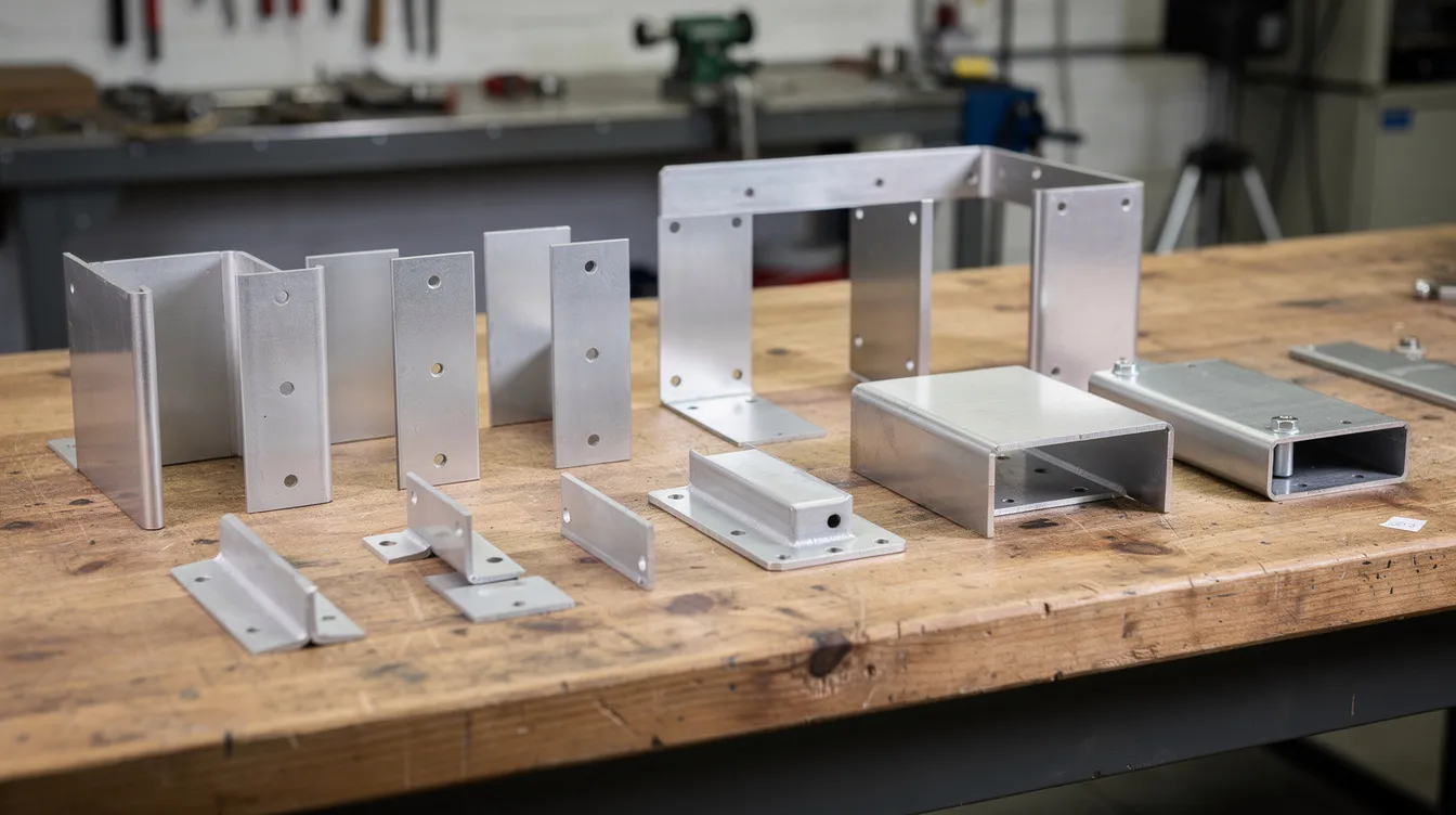
Design for Sheet Metal Bending: Practical Rules of Thumb
This section provides high-level design guidelines to make your parts “press-brake friendly.” These aren’t exhaustive specifications. They are practical starting points that reduce scrap, rework, and cost. Key design considerations for sheet metal bending include material type, thickness, and bend allowance.
Minimum bend radius by material family:
-
Mild/carbon steel (cold rolled, annealed): Inside bend radius ≈ 1× material thickness for 90° bends across the grain. If bending along the grain or working with thicker materials, increase to 1.5–2× thickness.
-
Stainless steel (304, 316): Higher yield strength and work hardening mean the minimum bend radius is typically 2× thickness or more, especially when bending along the grain.
-
Aluminum 5052 (soft temper): Inside radius ≈ 1× thickness is usually achievable. Soft temper allows tight bends without cracking.
-
Aluminum 6061-T6 (hard temper): Significantly more restricted. Across grain, expect at least 2× thickness. Along grain, 3–4× is common. Consider annealing before bending if the design demands tight radii.
-
Titanium: Low ductility, high strength. Inside radii typically ≥ 3–4× thickness. Specialized tooling and higher costs are the norm.
Minimum flange length:
-
For air bending, the minimum flange length should be at least 2.5× material thickness plus the inside bend radius. Shorter flanges risk deformation, warping, or slipping off the die.
-
Bottom bending and coining may require even longer flanges to accommodate the full V-die opening width.
Bend-to-bend spacing and successive bends:
-
Minimum spacing between adjacent bend lines should be at least material thickness plus inside bend radius to avoid tooling collision and material distortion during successive bends.
-
Z-bend step heights must provide clearance for the punch nose and any adjacent formed features.
Hole and cutout placement:
-
Proper hole placement is crucial to prevent deformation during bending. Keep hole centers at least one material thickness plus the inside bend radius from the bend tangent line. Holes too close to bends can cause deformation during bending, pulling the hole into an oval or distorting adjacent features.
-
Slots or cutouts crossing the bend line will distort unpredictably. Avoid them or add bend relief cuts.
Bend relief:
-
Bend reliefs are used when a bend terminates close to an edge to prevent tearing. These small notches at the ends of a bend line allow the material to fold cleanly without pulling or cracking at the bend edges.
Thickness and angle standardization:
-
Consistent material thickness is crucial for effective bending. Variation in sheet thickness causes inconsistent springback, which leads to angular errors across a batch.
-
Standardize bend angles to 90°, 45°, or 135° whenever possible. Nonstandard angles require additional setup, die changes, and programming time.
-
Bend length is limited by the maximum width of bending machines, so check your fabricator’s press brake capacity early.
Material Factors: Grain Direction, Springback & Hot vs Cold Bending
Material grain, strength, and ductility are the hidden variables that determine whether a bend comes out clean or cracks on the first hit. Material properties such as ductility and yield strength affect bending process requirements, and understanding them saves time during both design and production.
-
Grain direction: Sheet metal is produced by rolling, which aligns the grain structure in the rolling direction. Bending perpendicular to the material grain (across the grain) provides better ductility and allows smaller radii. Bending parallel to the grain direction increases cracking risk, particularly in aluminum alloys like 6061-T6, where the required radius may need to be 50–100% larger when bending along the grain. Always orient your bend lines relative to grain when possible. For stainless steel specifics, see our guide on how to bend stainless steel sheet metal.
-
Material types and behavior: Mild steel is the most commonly used bending material due to its good ductility and predictable forming behavior. Aluminum alloys can be bent to tight radii without cracking, provided the temper is appropriate (soft tempers like 5052-O are forgiving; hard tempers like 6061-T6 are not). Stainless steel contains at least 10.5% chromium for corrosion resistance, which also contributes to its higher yield strength and work-hardening tendency. Copper is a less common material used in sheet metal bending, typically seen in electrical or thermal applications where conductivity is paramount.
-
Springback: Springback occurs when metal tries to regain its original shape after the bending force is released. The material’s yield strength and the material stress in the bend zone drive this elastic recovery. Springback generally amounts to 1-2° of difference after bending. Typical ranges vary: soft aluminum (5052) shows about 1–2°; harder aluminum (6061-T6) can spring back 3–6°; cold-rolled mild steel typically 2–3°; and stainless steel 304/316 around 4–7°. Springback is influenced by material properties and bend radius: higher yield strength and larger bend radii produce more springback. The k-factor helps calculate springback in sheet metal bending by modeling neutral axis position. Compensation for springback is necessary to achieve desired angles. In practice, springback must be compensated for during the bending process, either by overbending the part, using CNC angle sensors for real-time correction, or selecting a method like coining that nearly eliminates elastic recovery. Springback typically amounts to 1-2° after bending for most common materials.
-
Laser-cut edge effects: Laser cutting produces edges with a heat-affected zone (HAZ) that may contain a recast layer or microcracks. If the bend line falls too close to these edges, cracks can initiate during forming. Edge dressing or grinding before bending is advisable for critical parts, and choosing cutting parameters that minimize HAZ helps.
-
Cold bending vs hot forming: Most precision sheet metal bending is cold bending, performed at room temperature. Hot forming is reserved for thick plate, high strength materials like titanium or hardened steels, where room-temperature ductility is insufficient. Hot forming allows tighter radii without cracking but adds equipment complexity, cost, distortion risk, and surface quality issues. Anebon’s core capability is cold-formed thin to medium gauge sheet for precision OEM parts.
From Flat Pattern to Finished Part: Process Flow at Anebon
Getting from a 3D CAD model to a finished bent part requires a controlled sequence of steps, each building on the accuracy of the one before. Here is the typical process flow at Anebon:
-
DFM Review: When you submit a 3D model or flat pattern, our engineers review material selection, thickness, inside bend radii, K-factor assumptions, hole positions relative to bend lines, proposed bend sequence, tooling availability, and surface finish requirements. We flag issues before cutting begins.
-
Flat Pattern Development: Using validated K-factor and bend allowance data specific to your material and our tooling, we generate an accurate flat pattern. This ensures the laser-cut blank will produce correct formed dimensions after bending.
-
Laser Cutting and Blanking: Our fiber lasers cut flat blanks to tight positional tolerances, providing consistent bend line locations and edge conditions. Accurate laser cutting improves bending precision by eliminating variability in where the bend line falls on the blank. Deburring follows where needed.
-
Press Brake Programming and Setup: We select the bending method (air, bottom, or coining), install appropriate punch and die tooling, set back-gauges and tonnage, and program springback compensation. For cosmetic surfaces, we use protective films, urethane tooling, or soft jaws.
-
Bending Operation: Bends are executed in the planned sequence, typically starting with outer flanges. CNC press brakes with angle sensors provide real-time feedback for accurate bending. Sheet metal bending can achieve accuracy levels of ±0.05 mm under favorable conditions with precision equipment.
-
Inspection: First-article inspection verifies critical angles, leg lengths, hole-to-bend distances, and radius using gauges or CMM. For production runs, statistical process control (SPC) monitors consistency.
-
Secondary Operations: After bending, parts may proceed to CNC machining, welding, powder coating, anodizing, or assembly depending on the project scope.
Typical achievable tolerances: ±0.2–0.3 mm linear and ±0.5° angular for standard production. For critical fit applications, we can hold ±0.1–0.15 mm linear and ±0.1–0.25° angular with additional setup and inspection.
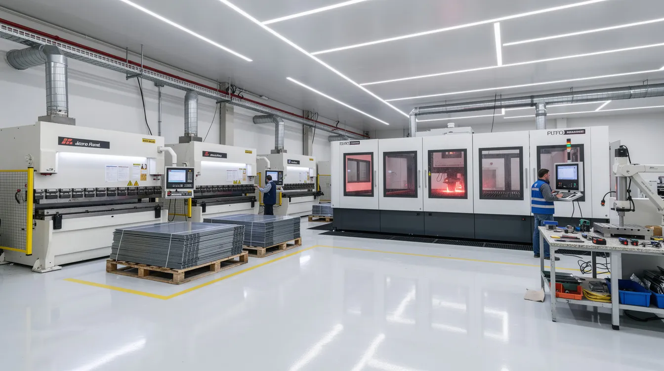
Calculating Bend Allowance & Using K Factor in Practice
This section gives a practical, engineer-friendly overview of calculating bend allowance for everyday design work. The goal is to help you understand how flat pattern dimensions relate to your finished part so you can catch errors before they reach the shop floor.
The standard bend allowance formula is:
BA = (π / 180) × A × (R + K × T)
Where:
-
A = bend angle in degrees
-
R = inside bend radius
-
T = material thickness
-
K = K-factor
Here is a worked example:
-
Material: 1.5 mm thick 304 stainless steel
-
Bend angle: 90°
-
Inside bend radius: 2.0 mm
-
K-factor: 0.38 (typical for stainless steel at this R/T ratio)
Calculating bend allowance:
BA = (π / 180) × 90 × (2.0 + 0.38 × 1.5) BA = (π / 2) × (2.0 + 0.57) BA = 1.5708 × 2.57 BA ≈ 4.04 mm
This means you need to allocate approximately 4.04 mm of material in your flat pattern for this single 90° bend, measured along the neutral axis arc.
Now, what happens if someone incorrectly uses K = 0.50 instead of 0.38?
BA = (π / 2) × (2.0 + 0.50 × 1.5) = 1.5708 × 2.75 ≈ 4.32 mm
That is a difference of about 0.28 mm per bend. On a part with multiple bends, this error compounds, potentially resulting in a part that is over a millimeter out of spec. The desired shape simply won’t match the design intent.
How K-factor varies by method:
-
Air bending: K ≈ 0.38–0.45 (neutral axis stays closer to mid-thickness)
-
Bottom bending: K ≈ 0.45–0.50 (more material compression)
-
Coining: K ≈ 0.45–0.50, but with the neutral axis pushed even closer to the inside surface under extreme compression
CAD sheet metal modules (SolidWorks, Inventor, etc.) embed bend tables that use K-factor or bend deduction values. At Anebon, we can share our recommended bend table values for specific material and tooling combinations, or validate customer-provided settings during DFM review. If you are working with an unfamiliar material or a new tooling setup, we recommend requesting a test bend to establish the correct K-factor empirically rather than relying on generic handbook values.
Choosing the Right Bending Method for Your Project
Selecting the right bending method at the RFQ stage saves time, reduces tooling cost, and improves first-pass yield. The decision depends on volume, tolerance requirements, surface finish, and material type. Here are concrete scenarios to guide your thinking:
Low-volume prototype in 2 mm 5052 aluminum (e.g., electronics or telecom bracket):
-
Use air bending on a CNC press brake. Generous radius (≈ 2× thickness), minimal tooling investment, fast setup. Protective tooling if cosmetic finish is needed. This is the most flexible approach for the desired bend geometry when designs may still evolve.
Medium-volume stainless steel medical enclosure (3 mm, 304) with critical mating surfaces:
-
Bottom bending or selective coining for bends where tight angle tolerance (±0.5° or better) is required. CNC press brakes with angle sensors compensate for the higher springback of stainless. Expect higher tooling cost but better repeatability.
High-volume automotive bracket in cold-rolled sheet steel (1.5 mm):
-
Bottom bending with standardized punch and die sets minimizes changeover. For high-stress joints, coining specific bends may be justified. Cost per part drops with volume, but tooling amortization must be factored in. Note that bending is less cost-effective for high-volume production over 1,000 units compared to stamping, so evaluate whether progressive die stamping makes more sense at scale.
Large-radius curved panels and housings:
-
Roll bending produces smooth, large-radius curves for guards, architectural panels, or cylindrical enclosures. Step (bump) bending on a press brake is an alternative for larger bend radii where roll bending equipment isn’t available.
Parts with painted, anodized, or pre-finished surfaces:
-
Rotary bending or urethane-top tools prevent surface damage. Protective film over the sheet during forming is standard practice. Avoid wiping or folding methods that drag tooling across the finished surface.
Anebon’s engineers recommend methods during quoting, balancing bend accuracy, cycle time, and tooling investment against your project requirements. We can provide test bends on your specific material to validate the approach before committing to production.
Cost, Lead Time & Quality Considerations in Sheet Metal Bending
Understanding the cost drivers in a sheet metal bending project helps you make smarter design decisions and set realistic expectations with your fabrication partner.
Primary cost drivers:
-
Material type and sheet thickness: thicker materials require higher tonnage for bending, increasing costs through greater machine wear, slower cycle times, and potentially specialized tooling.
-
Number of bends per part and bend complexity: each additional bend adds setup time, back-gauge repositioning, and potential for cumulative tolerance error.
-
Total bending line length and required precision: longer bends need larger press brakes. Tighter tolerances demand more inspection and slower, more controlled forming.
-
Tooling changes: nonstandard angles or radii require die changes and programming time.
How to optimize cost:
-
Standardize bend angles and radii across your design to reduce setup changes.
-
Accept the loosest tolerances your function allows.
-
Group similar bend features where possible.
-
Choose common material thicknesses and grades.
Lead times for overseas OEM projects:
-
Prototypes: typically 3–7 days if materials are in stock.
-
Production orders (small to mid volume): 2–4 weeks including bending, finishing, and inspection.
-
Complex parts with special alloys or finishes: 4–6 weeks or more, especially if specialized tooling is required.
Quality assurance: Anebon operates under ISO 9001:2015 with incoming material certification, first-article inspection (FAI) on all critical dimensions, and ongoing SPC for recurring production. We verify bend angles, radii, flatness, and bend-to-feature distances using calibrated gauges and CMM. Superior bend accuracy and surface protection-through protective films and non-marring specialized tooling-can reduce rework and total project cost, even when per-part bending cost is slightly higher.
Applications & Industries Using Sheet Metal Bending
Sheet metal bending is central to Anebon’s work across multiple customer industries. Common applications for sheet metal bending include automotive, aerospace, and electronics industries, but the process reaches much further. Here is how bending supports specific sectors:
Aerospace:
-
Avionics mounting trays, airframe brackets, interior panels. Design priorities: weight reduction, corrosion resistance, fatigue performance, and precise bends for tight assembly fitment.
Medical Devices:
-
Surgical equipment frames, instrument carts, stainless steel enclosures. Priorities: cleanability, corrosion resistance (stainless steel grades 304/316), cosmetic finish quality, and tolerance for mating surfaces that must seal or align precisely.
Automotive and EV:
-
Mounting brackets, chassis gussets, battery enclosures. Priorities: high volume, cost efficiency, uniform wall thickness, structural stiffness, and compatibility with coatings or galvanization.
Electronics and Telecom:
-
EMI-shielded housings, rack-mount panels, connector enclosures. Priorities: precise angles for mating, sharp angles for clean edges, hole-to-bend accuracy for connectors, and surface finish for paint or anodize.
Robotics and Industrial Machinery:
-
Robotic arm covers, machine guards, control panel enclosures. Priorities: larger sheet metal parts, sometimes roll-bent curved panels, paint adhesion, and integration with welded assemblies.
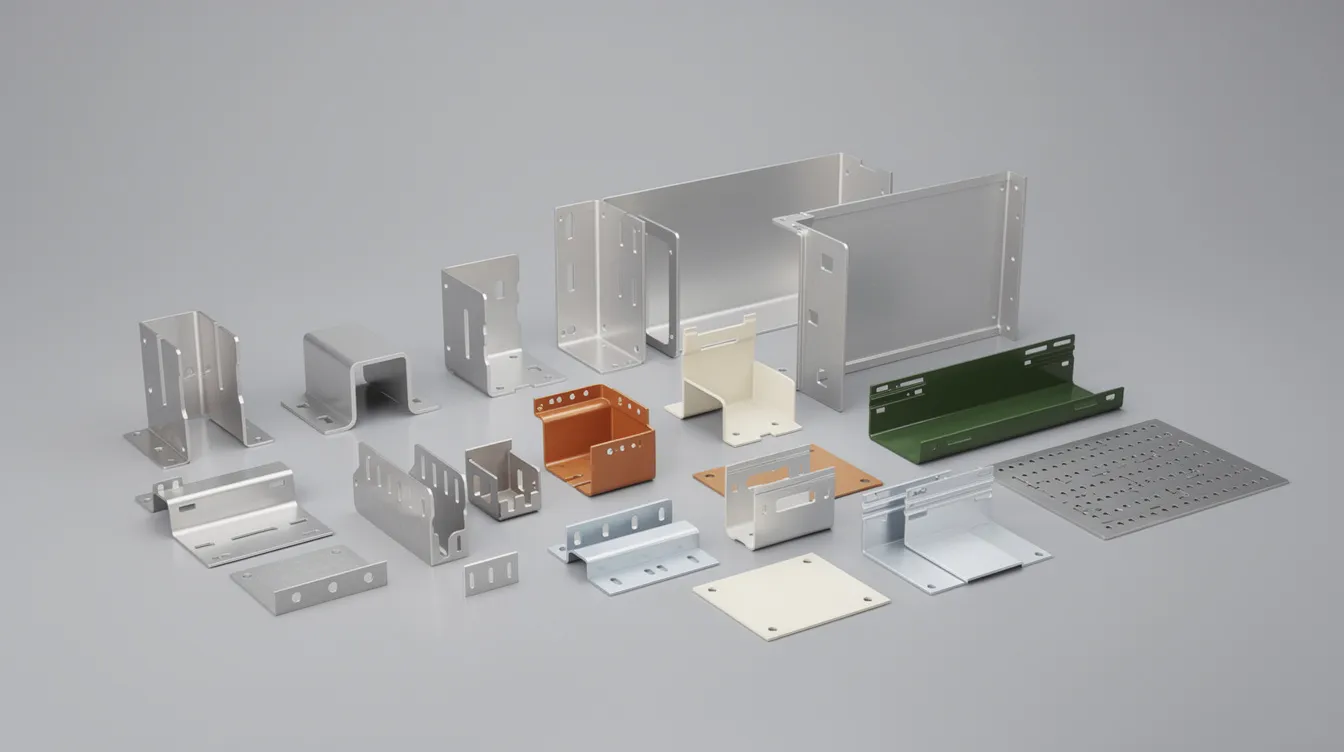
Design priorities differ by sector. In aerospace, you optimize for weight and fatigue life. In medical, for cleanability and the desired shape that accommodates sterilization paths. In automotive, for cost at volume. In electronics, for precise fit and EMI shielding. But across all of them, getting the bending operation right is what turns a flat metal sheet into a functional component.
Anebon supports both rapid prototyping and full production across these sectors from our Dongguan facility, providing custom precision sheet metal bending parts with full traceability.
Working with Anebon Metal Products Limited
Anebon Metal Products Limited was founded in 2010 in Dongguan, Guangdong, China. We hold ISO 9001:2015 and ISO 14001:2015 certifications, ensuring robust quality management and environmental practices across all our fabrication processes.
Bending capabilities:
-
CNC hydraulic and electric press brakes for air bending, bottom bending, and coining.
-
Tooling variety covering a wide range of V-die openings to support different R/T ratios and material types.
-
Surface-protective tooling (urethane, soft jaws, protective films) for cosmetic and pre-finished parts.
-
Achievable tolerances down to approximately ±0.1 mm on bends and ±0.002 mm on machined features.
Materials we bend:
-
Aluminum (5052, 6061, and others), stainless steel (304, 316), carbon steel, mild steel, titanium, and copper. We maintain empirical bend data for our most-used alloys.
Value-added services:
-
DFM feedback on bend radius, k factor, hole placement, grain direction, finish, and cost implications before you commit to production.
-
Integrated process from laser cutting and deburring through bending, CNC machining, welding, and surface finishing (anodizing, powder coating, painting).
-
First-article inspection, material certifications, and full QA documentation for traceability.
Ideal for: Overseas OEMs, design engineers, and R&D teams who need high strength materials formed to tight tolerances with repeatable quality, whether for a single prototype or ongoing production.
Ready to start your next sheet metal bending project? Send us your 3D CAD models and flat patterns for a free DFM review. Our engineering team typically responds within 24–48 hours for prototype parts and 3–5 business days for complex assemblies. Request a quote today and let us help you bend metal right the first time.