Understanding Surface Texture Ra: Key Insights for Manufacturing
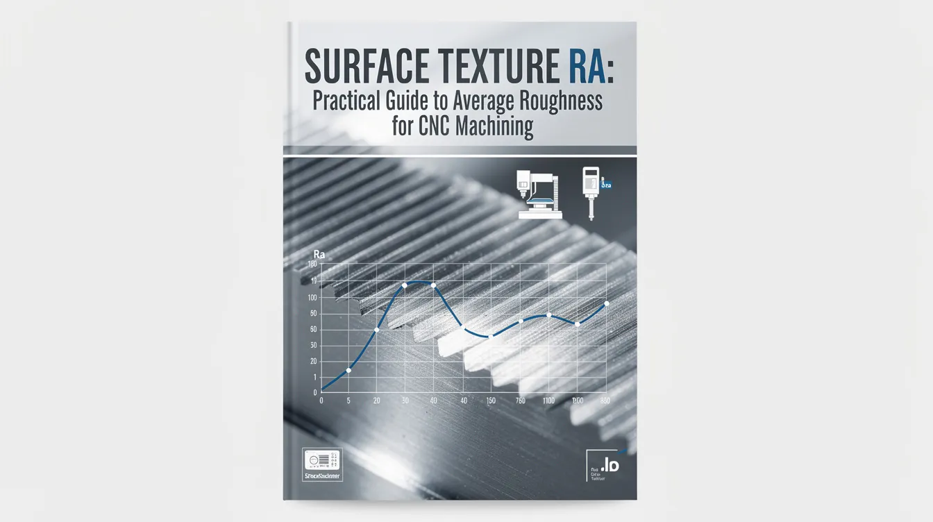
Surface Texture Ra: Practical Guide to Average Roughness for CNC Machining
Surface texture Ra is a widely used parameter in manufacturing that tells you how smooth or rough a machined surface actually is. Whether you are specifying finishes on technical drawings or evaluating quotes from a contract manufacturer, understanding Ra helps you make better decisions about function, cost, and quality.
This guide walks through what Ra means in practice, how it is measured, how it affects part performance, and how to choose the right Ra value for your project.
What is surface texture Ra? (fast, high-level answer)
Ra stands for arithmetic average roughness, sometimes called center line average or roughness average. It is the most common surface roughness parameter used on engineering drawings worldwide.
In simple terms, Ra is the average height of microscopic peaks and valleys above and below a mean line, measured along a defined evaluation length on a surface. Surface roughness measures the smoothness of a surface’s profile, and Ra provides a quantifiable measure of how smooth or rough a surface is. Ra measures average surface roughness in micrometres (µm), though it can also be expressed in micro inches (µin). For quick shop-floor conversions, one micrometer is approximately 40 micro-inches (precisely 1 µm ≈ 39.37 µin).
Many mechanical engineers use “surface finish,” “surface texture,” and “surface roughness” almost interchangeably in conversation. Technically they describe different things (more on that below), but when someone says “what’s the finish on that part?” they usually mean the Ra value.
Here is a simple comparison: a turned shaft finished to Ra 0.8 µm will feel smooth to the touch and is suitable for light bearing or sealing contact. Compare that with an as-cast surface at Ra 6.3 µm, where you can see and feel the rough surfaces and texture clearly. At Anebon Metal Products Limited, we routinely work with Ra values from about 0.4 µm (fine grinding or polishing) to 6.3 µm (standard rough machined or pre-finishing surfaces) on cnc machined parts across aluminum, steel, titanium, and engineering plastics.
Surface finish vs surface texture vs surface roughness
These three terms are related but describe different things, and using them correctly prevents miscommunication between design and manufacturing teams.
-
Surface texture is the most comprehensive term. It covers the complete surface geometry, including roughness (small-scale irregularities), waviness (longer-wavelength undulations), and lay direction (the directional pattern left by the cutting tool or finishing operation). Think of it as the full fingerprint of how a surface was made.
-
Surface roughness refers specifically to the fine-scale vertical deviations-the closely spaced peaks and valleys that make a surface feel gritty or smooth. Ra is one of several surface texture parameters that quantify this roughness.
-
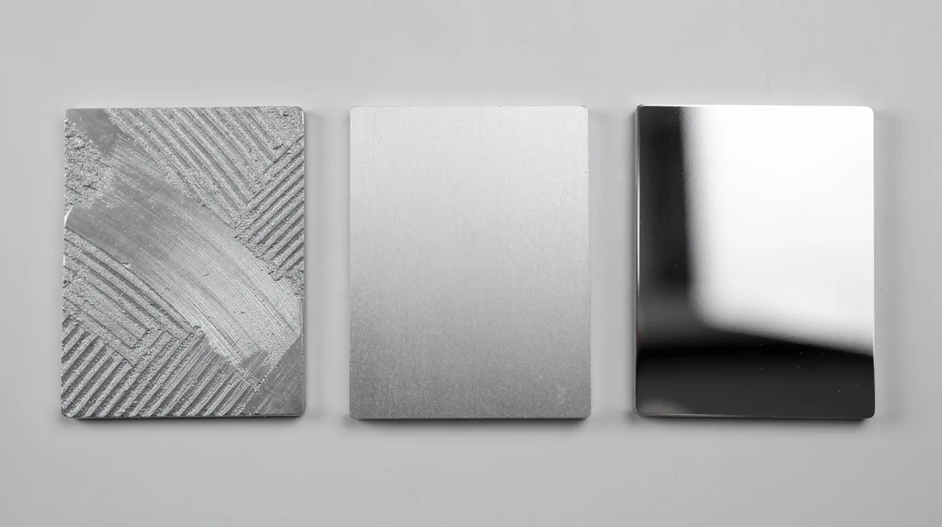
Surface finish in machining shops often describes the practical end-state of a product’s surface after a manufacturing process or post-treatment: “as-machined,” “bead blasted,” “anodized,” “mirror polished.”
For example, the same machined surface might be described as:
-
Roughness: Ra 1.6 µm, Rz 8 µm
-
Finish: bead blasted + Type II anodize
-
Texture: milled, lay direction parallel to long axis, waviness controlled
At Anebon, we use both numeric roughness parameters (Ra, Rz) and process descriptors (as-machined, anodized, bead blasted, polished) in drawings and quotes. This eliminates ambiguity and ensures the desired surface finish matches what gets manufactured.
Key roughness parameters: Ra, Rz, RMS and peak-to-valley
Ra is not the only roughness parameter engineers use. Depending on the application, other key parameters may be just as important.
-
Ra (roughness average) is the arithmetic average of the absolute deviations from the mean line across the sampling length. Non-math version: imagine drawing a perfectly flat line through the middle of a surface profile, then measuring how far, on average, every point strays above or below that line. That average values of those absolute values is your Ra.
-
Rz (average maximum height) divides the roughness profile into five equal sampling lengths and measures the vertical distance from the highest peak to the deepest valley in each segment, then averages those five values. Rz measures the average height of the five highest peaks and valleys, making it far more sensitive to occasional deep scratches or burrs than Ra. Ra is typically lower than Rz for the same surface-often by a factor of 4 to 7×.
-
Rt or Rmax is the single maximum peak to valley distance within the evaluation length. It captures the worst-case scenario and is critical for sealing applications or fatigue-sensitive parts.
-
Rq (root mean square roughness) is the root mean square average of deviations from the mean line. Because it squares each deviation before averaging, the square average weights larger deviations more heavily. A common rule of thumb: Rq ≈ 1.1 × Ra for typical machined surfaces.
The concept of peak to valley matters whenever a single extreme feature could cause a functional failure-a leak path under a gasket, a stress riser on a rotating shaft, or a scratch that compromises a coating. Engineers often supplement Ra with other parameters for critical applications, adding Rz or Rmax limits to catch what the ra average alone cannot.
For most CNC machined OEM components, Anebon’s customers specify Ra. But for sealing and bearing surfaces, they often add Rz or Rmax limits to bound those extremes.
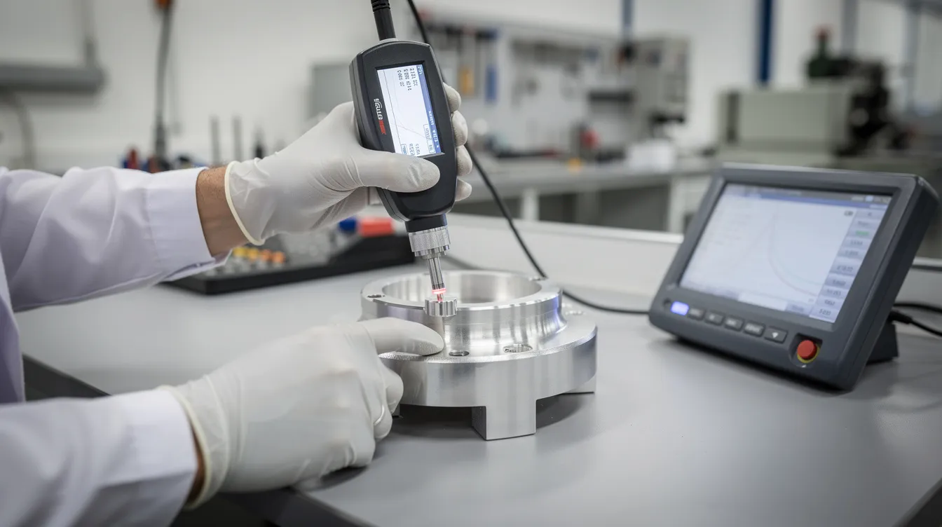
How Ra is measured: contact and non-contact methods
Surface roughness is typically measured using either contact stylus instruments or non contact optical systems, and each approach has trade-offs worth understanding.
Contact profilometers are the workhorse of surface measurements in manufacturing. A diamond stylus traverses across the surface at controlled speed and force, recording vertical deviations as it rides over the roughness profile. Software then filters the data (separating roughness from waviness using defined cut-off lengths) and calculates Ra, Rz, Rt, and other parameters. Surface roughness is measured using a profilometer in the vast majority of machine shops and quality labs worldwide. Contact measurement methods are standardized under ISO 4287 and ASME B46.1, making them widely accepted for compliance documentation.
Non contact methods include white light interferometry, confocal microscopy, and laser scanning profiling techniques. These capture 3D surface topography without physically touching the part, making them ideal for very fine finishes or delicate surfaces. Optical profiling is suitable for delicate surfaces where a stylus might cause damage. However, non contact methods can be sensitive to surface reflectivity and steep slopes.
Measurements are taken perpendicular to the lay direction with defined sampling length and cut-off lengths per ISO 4287/ISO 4288. Without specifying these parameters, surface roughness tester readings from different vendors may not agree.
Anebon uses calibrated contact and non-contact equipment for Ra verification and can provide surface roughness reports on request.
Typical Ra values for CNC machining and manufacturing processes
Rather than a full surface roughness comparison chart, here is a practical ladder linking common Ra ranges to the various manufacturing processes that produce them. Ra values range from 12.5 μm (very rough) to 0.4 μm (very smooth), and the standard surface finish for machined parts is 3.2 μm Ra.
-
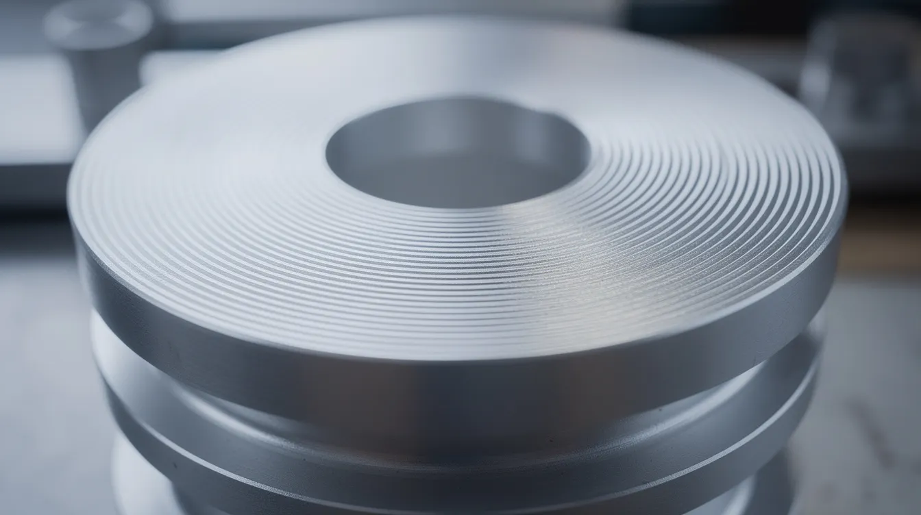
12.5–6.3 µm Ra: as-cast, rough milling or turning. These rough surfaces are typical for internal features, non-critical faces, or parts destined for secondary finishing. Very rough finishes at this level are usually produced by casting, forging, sandblasting, or coarse grinding rather than precise cnc machining.
-
3.2 µm Ra: standard as-machined CNC milling/turning finish. A typical CNC machining finish is Ra 3.2 µm-this is what most shops deliver without special instructions. Suitable for general-purpose brackets, housings, and enclosures.
-
1.6–0.8 µm Ra: fine machining with optimized tools and feeds, or with a dedicated finishing pass. Achievable using sharper tools, lower feed rates, and high speeds. Appropriate for mating faces, visible surfaces, and moderate-contact interfaces.
-
0.4–0.2 µm Ra: precision grinding, lapping, or polishing. Required for critical sealing faces, optical surfaces, precision bearings, and mold cavities.
Anebon’s standard CNC as-machined finish is typically around 3.2 µm Ra, and 1.6 µm Ra is achievable with fine machining on request. For guidance on optimizing finish during turning operations, see our guide to achieving superior surface finishes in CNC turning.
Secondary processes also shift Ra values:
-
Bead blasting creates a matte finish using small glass beads, typically producing Ra ~2.5–4.0 µm depending on media size and pressure.
-
Anodising adds a protective oxidised layer to metal parts. Anodising type II produces a coating thickness of up to 25 μm and generally preserves the substrate’s relative smoothness, while anodising type III can achieve a coating thickness of up to 125 μm and may slightly alter the surface profile.
-
Manual polishing can push Ra below 0.4 µm for cosmetic or functional requirements.
Different manufacturing processes-CNC machining, die casting, sheet metal forming-naturally yield different roughness ranges before finishing. Material properties also matter: aluminum alloys like 6061 and 7075 generally achieve a smoother finish at given parameters than stainless steel or titanium.
How Ra affects function: friction, sealing, fatigue and coatings
Selecting the right ra value is a functional decision, not just an aesthetic one. Surface roughness affects how parts interact with their environment, and getting the specification wrong can cause real performance failures.
Friction and wear. Surface roughness affects friction between sliding parts. Lower Ra often reduces friction for sliding parts like shaft-bushing assemblies-smoother surfaces reduce friction and improve durability. However, overly smooth surfaces can starve lubrication films, leading to stick-slip or boundary lubrication failure. A rougher surface can increase wear performance in certain applications by retaining oil in microscopic valleys. For a shaft running inside a bushing, Ra 0.4–0.8 µm is a common target.
Sealing surfaces. Surface roughness impacts the effectiveness of seals in mechanical parts. Even when Ra looks acceptable, excess peak-to-valley height or deep isolated valleys can create leak paths under gaskets or O-rings. This is why CNC machining surface finish impacts functional performance in sealed assemblies-Ra alone is not enough; Rz or Rmax limits are often needed.
Fatigue and stress. Sharp peaks and high Rz act as stress concentrators on rotating shafts, structural brackets, and any part subject to cyclic loading. Controlling surface roughness to Ra 0.8–0.4 µm can meaningfully improve fatigue life.
Coatings and adhesion. Surface roughness can affect adhesion of coatings and finishes. A slightly higher Ra improves bonding for paint, powder coating, and adhesive joints through mechanical interlocking. Extremely smooth surfaces may need additional pre-treatment. For more on this topic, see our article on surface treatments in CNC machining.
Corrosion and cleanliness. Smoother Ra reduces crevices where corrosive media or contaminants can accumulate. Low Ra surfaces are essential for cleanliness in food processing, and very low Ra values are essential in the pharmaceutical industry to prevent contamination. Ra impacts how parts fit together and wear rates across all these applications.
A concrete example: for an industrial gear cover (non-contact, painted), Anebon might accept Ra 3.2–6.3 µm. For a medical device housing or surgical tool component, we typically work with Ra 0.4–0.8 µm, specifying both Ra and Rz limits along with controlled lay direction.
Choosing Ra for your project: common surface finish targets
The “right” Ra depends on function, tolerance, and cost. Over-specifying Ra on every face adds unnecessary manufacturing costs without adding value. Here is how to think about typical Ra choices:
-
6.3–3.2 µm Ra: economical for brackets, housings, non-critical faces, or parts to be painted. Achieved with standard CNC milling or turning, no special finishing passes.
-
1.6 µm Ra: general-purpose precision surfaces, light bearing faces, and visible machined surfaces. A modest cost increase (~20–50% on affected faces), requiring optimized feeds and a finishing pass.
-
0.8–0.4 µm Ra: high-precision fits, sealing lands, mold cavities, and high-speed moving parts. May require grinding, honing, or polishing. Smoother surfaces reduce friction and increase wear performance at these levels.
Anebon commonly supplies cnc machined parts at Ra 3.2 µm as standard and offers 1.6, 0.8, and 0.4 µm Ra when design requirements justify the added operations. For detailed guidance on selecting the right surface roughness for your parts, our engineering team can help during quoting.
Ra requirements interact with dimensional tolerances. Tighter Ra and tight tolerances may require additional grinding or lapping and careful process planning-sometimes on different machines entirely.
We recommend choosing Ra together with the expected post-process (anodizing, electroplating, bead blasting, polishing) since these can increase or decrease the final roughness average. Share your functional needs-sliding contact, vacuum seal, cosmetic front panel-with Anebon so our manufacturing engineers can propose realistic Ra targets and the most cost-effective path to achieve them.
Same Ra, different surfaces: why Ra alone can be misleading
Ra is a pure statistical average that cannot capture spatial patterns. Two surfaces with the same Ra can behave very differently in service.
Consider three surfaces, all measured at Ra 1.6 µm:
-
Surface A has many shallow, closely spaced peaks and valleys-a uniform finish typical of fine milling.
-
Surface B has broad, smooth plateaus interrupted by occasional sharp spikes.
-
Surface C has relatively flat peaks but deep, narrow valleys.
Ra cannot distinguish between peaks and valleys, and it cannot distinguish between different surface profiles like these. Yet Surface B may scratch a mating part, Surface C may leak under a gasket, and only Surface A provides the uniform finish expected.
Parameters like Rz, Rsk (skewness), and the bearing ratio (material ratio curve) help describe these differences. Rsk tells you whether the roughness profile is peak-dominated (sharp spikes that cause wear) or valley-dominated (oil-retention pockets that improve lubrication). The bearing ratio curve shows what fraction of the surface is above a given depth-critical information for sealing applications.
For critical applications-hydraulic sealing, aerospace structural parts, medical implants-Anebon engineers may recommend specifying both Ra and additional parameters or process controls. We encourage designers to avoid relying on legacy “one-size-fits-all” Ra callouts copied from older drawings without reviewing the actual functional needs of each surface.
Converting Ra between units and relating Ra to other scales
Global projects often need to convert Ra between metric and imperial units, and sometimes to correlate Ra with older roughness grade numbers or other indicators. Here is a quick surface roughness chart for common conversions:
|
Ra (µm) |
Ra (µin) |
ISO N-Grade |
|---|---|---|
|
0.4 |
16 |
N5 |
|
0.8 |
32 |
N6 |
|
1.6 |
63 |
N7 |
|
3.2 |
125 |
N8 |
|
6.3 |
250 |
N9 |
The rule of thumb: 1 µm ≈ 39.37 µin, often rounded to 40 µin for shop-floor calculations. You can convert Ra between metric and imperial using this ratio for any value.
Approximate relationships exist between Ra and Rz (Rz ≈ 4–7 × Ra for most machined surfaces), but these are rough estimates and not suitable for safety-critical design. Always specify Rz explicitly when it matters.
Older drawings may use roughness grade numbers (N5, N6, N7, etc.) per ISO 1302 instead of numeric Ra. If you encounter these on legacy specs, use a current surface finish conversion chart or ask your manufacturer to interpret them. Anebon’s engineering team can help convert Ra, Rz, RMS (root mean square), center line avg, and grade numbers into a modern, manufacturable requirement.
Surface roughness, manufacturing process and cost
Every increment in surface quality-lower Ra-generally increases machining time, tool wear, inspection effort, and therefore unit cost. Ra specifications directly affect production costs, so understanding the cost curve helps you make smart trade-offs.
CNC machining parameters directly influence the resulting ra value:
-
Feed rate and step-over: higher feed leaves deeper scallops and higher Ra. Reducing feed improves finish but increases cycle time.
-
Cutting tool geometry: a cutting tool with a larger nose radius and appropriate rake angle produces a smoother finish. Sharper tools and fresh inserts outperform worn ones.
-
Machine rigidity and vibration: chatter or fixture instability degrades finish regardless of programmed parameters. The impact of high-speed CNC machining on surface quality is significant.
-
Material selection: free-machining alloys (brass, 6061 aluminum) achieve lower Ra more easily than gummy stainless steels or tough titanium grades.
Achieving Ra 3.2 µm may require only one standard CNC pass. Reaching Ra 0.8 µm may need multiple finishing passes or a change in manufacturing process-grinding, honing, or polishing-which can double or triple cost on those features.
Sometimes a rougher visual appearance is desired. Very rough finishes are sometimes cheaper to obtain by using processes like bead blasting or shot blasting rather than deliberately degrading CNC toolpaths.
In Anebon’s quoting, very low Ra requirements affect both piece price and lead time. We always encourage specifying the “loosest” Ra that still meets functional needs to keep projects cost-effective.
Practical Ra guidelines for common Anebon applications
Here is a quick reference for design engineers working with Anebon on CNC machined parts, die castings, and sheet metal components:
-
CNC machined enclosures and brackets: typically 3.2–1.6 µm Ra as-machined or with light bead blasting. Economical, fast, and suitable for non-critical or internal faces.
-
Shafts, pins, and bush interfaces: typically 1.6–0.8 µm Ra with controlled lay direction. The typical machined surface for these applications balances low friction with adequate lubrication retention.
-
Precision jigs, fixtures, and gauge surfaces: often 0.8–0.4 µm Ra with grinding or polishing. Requires dedicated secondary operations and tighter quality control.
-
Die cast parts before painting or powder coating: accept higher Ra (6.3–3.2 µm) from the casting process and rely on coating for visual appearance.
In medical, robotics, and electronics projects, Anebon often works with customer-specific Ra and Rz bands for critical mating surfaces. The visual appearance of a product’s surface matters in these industries, and so does functional performance.
Mark which surfaces need tight Ra on the drawing, rather than applying a global ultra-smooth requirement to every face. This single practice can cut manufacturing costs by 20–40% on multi-feature parts.
Anebon can help adjust Ra specs when moving from prototype to mass production, balancing performance with production economics for a smoother finish where it counts and a more economical approach everywhere else.
Ra measurement and quality assurance at Anebon Metal Products Limited
Anebon holds ISO 9001:2015 and ISO 14001:2015 certifications, and our quality systems are built around the expectations of overseas OEM customers across aerospace, medical, automotive, and electronics sectors.
We use calibrated surface roughness testers-both contact profilometers and non-contact optical systems-as part of routine in-process and final inspection for CNC machined, die cast, and sheet metal parts. Surface measurements are integrated with CMM and other dimensional inspections when Ra is critical to function or assembly, following our quality assurance inspection protocols.
Anebon can supply Ra and Rz measurement records, inspection reports, and material certificates according to customer or industry requirements. DFM reviews during quoting flag impractical Ra callouts early and propose alternative finishes or processes that achieve equivalent performance at lower cost.
We encourage customers to send 3D models and 2D drawings with any known Ra targets so our engineers can suggest optimal combinations of machining and finishing processes before production begins.

Summary and next steps
Ra-roughness average-is the primary metric for specifying and controlling surface finish on CNC machined parts. It gives you a single number that captures the average roughness of a surface, making communication between design and manufacturing teams straightforward.
Correct Ra selection balances function, manufacturability, and cost, and should always be chosen with the actual manufacturing process in mind. Remember that Ra alone may not describe all functional aspects of surface texture, especially where sealing, fatigue, or lubrication are critical. In those cases, supplement Ra with Rz, Rmax, or other parameters.
Ready to get started? Upload your CAD files and 2D drawings, specify your target Ra values or describe the functional requirements for each critical surface, and request a detailed quote with surface finish options from Anebon Metal Products Limited. Our engineering team provides DFM feedback on surface finish and roughness parameters at the quoting stage-so you can be confident that what gets quoted is what gets delivered.