Understanding Sheet Metal Manufacturing: Key Processes and Techniques
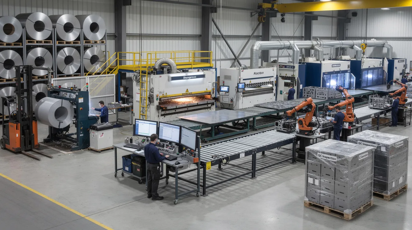
Sheet Metal Manufacturing: From Raw Coil to Finished OEM Assemblies
Introduction to Sheet Metal Manufacturing
Sheet metal manufacturing encompasses everything from producing raw coil and plate stock to converting those sheets into precision components and assemblies. It is a manufacturing process that touches nearly every industry-from EV battery enclosures and 5G base station cabinets to medical device housings shipped worldwide in 2025. Sheet metal is strong and durable yet malleable, making it ideal for enclosures, brackets, panels, and structural frames. It is also 100% recyclable, saving energy in production and reducing environmental impact across the supply chain.
Anebon Metal Products Limited is an ISO 9001:2015 and ISO 14001:2015 certified manufacturer in Dongguan, China, serving overseas OEMs since 2010. This article walks through the entire product journey-from raw material to finished product-covering cutting (including laser cutting), forming, joining, finishing services, and inspection. Sheet metal fabrication is cost-effective for large production runs and equally practical for low volume prototypes, which is why it remains a backbone of end use production across aerospace, medical, automotive, electronics, robotics, and industrial machinery.
What Is Sheet Metal and How Is It Made?
Sheet metal refers to flat steel, aluminum, copper, brass, and other alloys rolled to thicknesses typically between 0.5 mm and 6.0 mm. Anything thicker is generally classified as plate. Thickness is specified in millimeters or gauges-for example, 20 MSG steel is approximately 0.912 mm, while 14 MSG is about 1.897 mm. Common materials include aluminum, brass, copper, and steel, each chosen for specific properties: aluminum is lightweight and corrosion-resistant; steel is known for its strength and durability; copper is excellent for electrical applications and good conductivity properties; and brass is valued for its acoustic properties.
The upstream manufacturing process starts with melting and casting slabs, followed by hot rolling and cold rolling to reach the target thickness, plus annealing or tempering to achieve the required mechanical properties. The result is either coil stock or flat sheets. OEM engineers specify coil stock when continuous feeding suits high volume production runs, and flat sheet stock when working with individual or lower-volume parts. Standard sizes include 1000 × 2000 mm and 1250 × 2500 mm. Consistent incoming metal sheet quality-verified through mill certificates for alloy, temper, and thickness tolerance-directly affects dimensional accuracy, flatness, and downstream process stability.
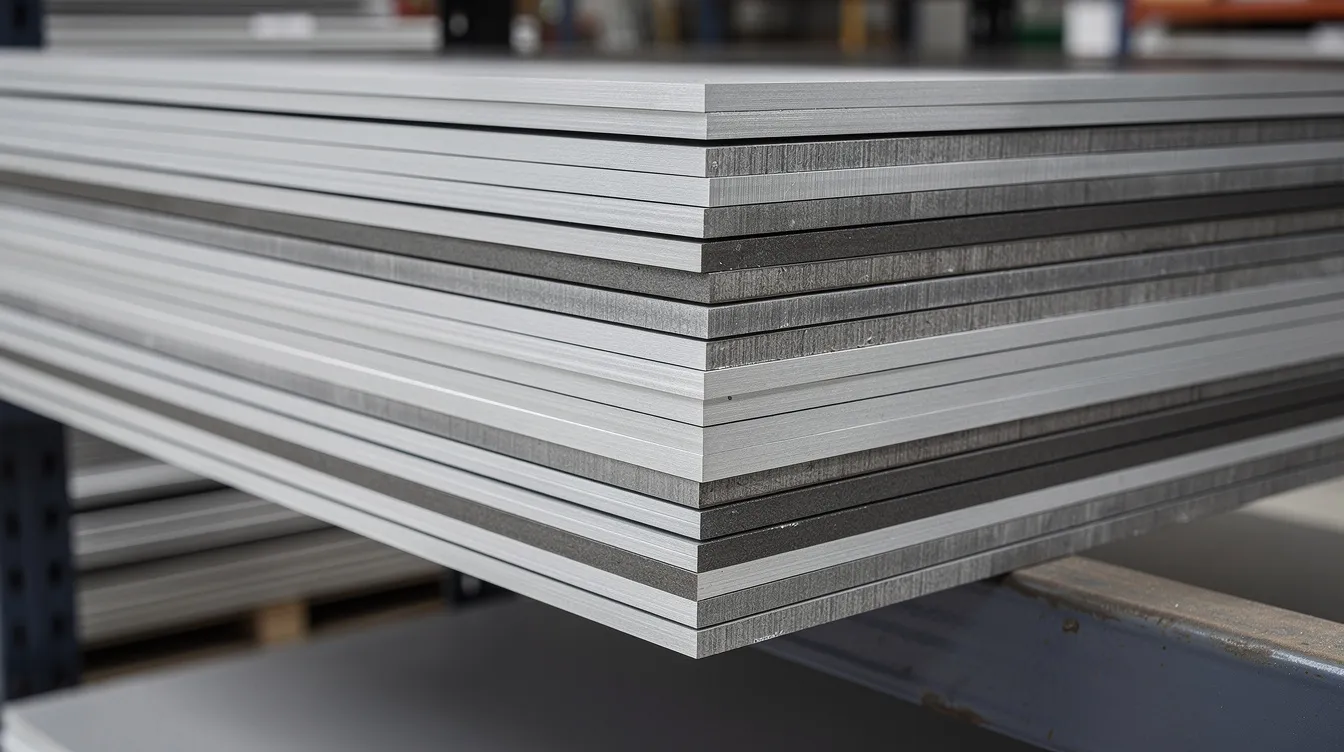
Overview of the Sheet Metal Manufacturing Process
The sheet metal fabrication process generally involves three broad phases: design, fabrication, and finishing. Sheet metal fabrication transforms flat metal sheets into shapes through a sequence of operations that starts with an RFQ and ends with packed, inspected parts ready to ship.
At Anebon, we support customers from rapid prototyping-sometimes producing a single sheet part in a few days-through pilot runs and stable production. The master definition of every part lives in digital data: 3D CAD models built in cad software (STEP, IGES, or Parasolid) plus 2D engineering drawings with tolerances, hole callouts, bend radii, and surface finish notes. On any given part, multiple fabrication processes may be combined-laser cutting, CNC punching with a punch press, press brakes forming, tapping, spot welding, and hardware insertion-all selected based on quantity, accuracy requirements, and cost targets.
Step‑by‑Step Sheet Metal Manufacturing Process
Below is a practical, engineer-friendly walkthrough of each stage, with numbers and examples realistic for a modern precision metal fabrication shop operating in 2025–2026.
1. Design Input and Engineering Drawings
Projects begin when customers supply 3D CAD files and engineering drawings (PDF or DWG), including revision dates. The final shop drawing must define material grade and temper, sheet thickness, bend radii, tolerances, hole sizes, thread specs, weld symbols, and surface treatments such as powder coating or chem film. Precision is crucial for custom sheet metal fabrication, and maintaining consistent wall thickness and proper bend radii is key for manufacturability.
Anebon performs design for manufacturability checks on every quote, reviewing minimum flange lengths, hole-to-edge distances, and relief cuts for bends. Computer aided design files allow us to flag issues early. DFM feedback during quoting-often within 24–48 hours-can eliminate tooling changes and scrap, especially during rapid prototyping. Design for manufacturability optimizes production efficiency across all design specifications.
2. Material Selection and Common Materials
Material selection in sheet metal fabrication must consider corrosion resistance, mechanical properties, weight, conductivity, and cost. Anebon regularly works with:
-
Aluminum 5052-H32, 6061-T6, 6063 – for bent enclosures, heat sinks, lightweight panels
-
Stainless steel 304 and 316L – for food, medical, and outdoor equipment
-
Mild steel SPCC / DC01 / Q235 – for structural brackets and painted housings
-
Galvanized steel – for corrosion resistant finish without additional coating
-
Copper and brass – for electrical components and connectors
Why choose 5052-H32 over 6061-T6 for a bent enclosure? 5052 has superior elongation and is less prone to cracking during bending sheet metal, while 6061-T6 offers higher strength for machined interfaces. Matching the sheet alloy to any subsequent cnc machining or die casting in the same assembly simplifies qualification.
3. Cutting: From Flat Sheet to Blank
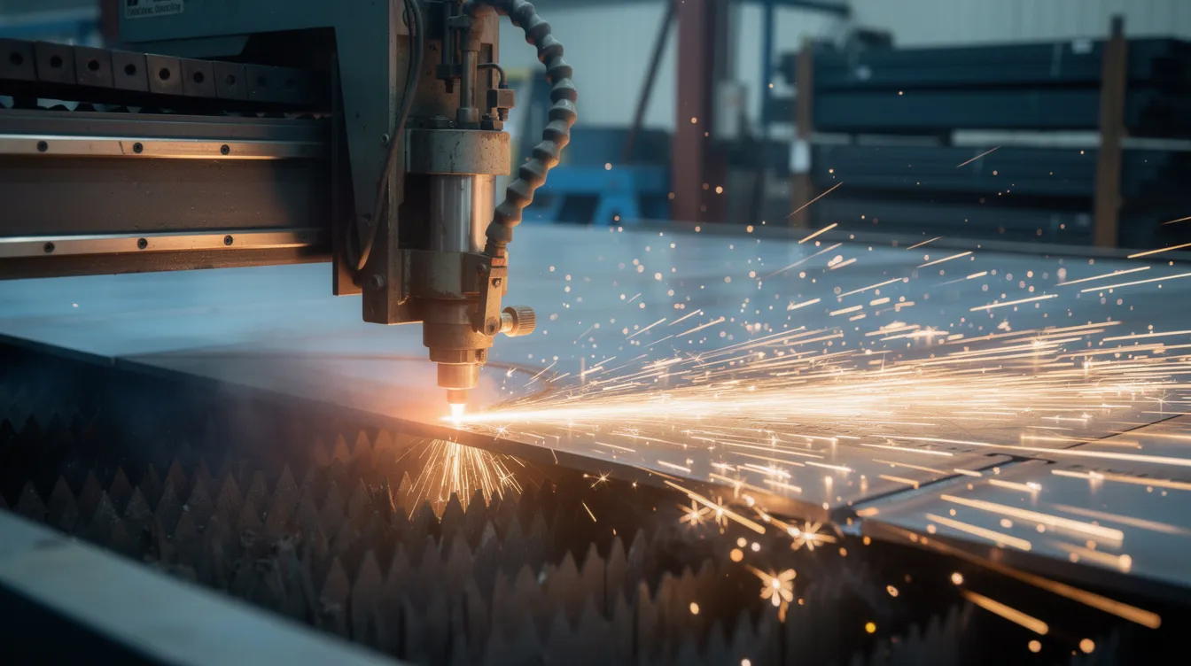
Sheet metal cutting is the first major fabrication step, transforming full sheets into blanks with the required 2D profile. Cutting methods include shearing, laser cutting, punching, and waterjet cutting. Common cutting techniques include laser and water jet cutting, plus plasma cutting for heavier gauges.
|
Method |
Best For |
Typical Precision |
|---|---|---|
|
Laser cutting |
Complex profiles, clean edges, thin–medium stock |
±0.05–0.1 mm |
|
CNC turret punching |
Repetitive holes, louvers, medium thickness |
±0.1 mm |
|
Shearing |
Straight-line cuts on large sheets |
±0.2 mm |
|
Plasma cutting |
Thicker metal sheets efficiently |
±0.5 mm |
|
Water jet cutting |
Heat-sensitive materials, high pressure water with abrasives |
±0.2 mm |
Laser cutting uses a high-powered laser for precision cuts on up to 20 mm carbon steel, 12 mm stainless steel, and 8 mm aluminum. Plasma cutting efficiently cuts through thicker metal sheets. Water jet cutting uses high-pressure water mixed with abrasives, avoiding generating heat entirely. Shearing applies mechanical force to cut metal sheets along straight lines.
3D CAD files are converted into nesting programs that arrange multiple pieces on a single sheet to minimize material waste. Sheet metal fabrication allows for production with minimal material waste when nesting is optimized-scrap rates of 5–15% are typical. CNC machines offer high precision in sheet metal cutting, which is why high precision OEM work typically favors laser cutting over other cutting techniques.
4. Forming and Bending
Forming processes include bending, stamping, rolling, and deep drawing. Press brakes are the workhorse for converting flat blanks into 3D parts, using V-dies, gooseneck punches, and other matched tooling to form sheet metal into the desired shape.
Key design parameters for bending:
-
Minimum inside bend radius: typically ≥ 1× material thickness
-
Bend allowance and K-factor determine flat-pattern length
-
Maximum part length per bend: 2,500–3,000 mm depending on machine
-
Angle tolerances: ±0.5° to ±1° standard
Sheet metal bending requires attention to the inside bend radius to prevent cracking, especially in harder tempers. Springback occurs when sheet metal returns to its original shape after being bent, and it must be compensated through tooling or overbending. Other forming operations include rolling for cylindrical parts, embossing for stiffening ribs, and hemming to remove sharp edges. Wrong bend relief or too-tight flanges cause cracking, distortion, or interference during assembly-problems that proper DFM review prevents.
5. Secondary Machining and Piercing
After cutting and forming, further processing such as countersinking, tapping, reaming, and small-feature milling is performed on CNC machining centers. Some critical features-precision bearing holes, for instance-are machined after forming instead of during laser cutting for higher accuracy.
CNC machinery offers precision within ±0.002 mm tolerances, supporting high precision assemblies. Regular calibration maintains CNC equipment accuracy across production lots. By combining sheet metal fabrication with cnc machining and die casting, Anebon delivers complete mechanical assemblies rather than just loose metal parts.
6. Joining and Assembly
Assembly techniques include welding, fastening, and various finishing treatments. The main assembly methods used in sheet metal fabrication are:
-
MIG welding – ideal for strong, thick materials like steel brackets
-
TIG welding (tungsten inert gas) – best for thinner materials like aluminum and stainless steel medical frames
-
Spot welding – rapid joining for thin steel cabinets and enclosures
-
Riveting – fastens two or more metal pieces together; blind rivets are used when access is only available from one side
-
PEM inserts – self-clinching fasteners for electronics chassis where secure thread points are needed
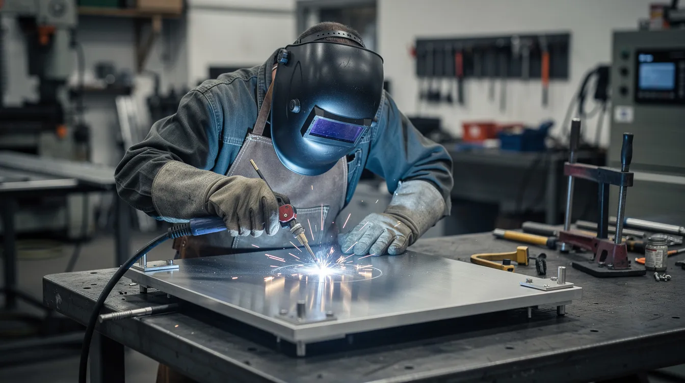
Welding is a common method for joining sheet metal parts. Heat management is crucial to avoid warping during high-temperature processes like welding, so fixture design and weld sequence are carefully controlled to maintain dimensional accuracy on larger weldments. Anebon can supply sub-assemblies or fully assembled units, including installation of hinges, locks, seals, and purchased components.
7. Surface Finishing and Corrosion Protection
Surface finishing is both functional and aesthetic-it provides a corrosion resistant layer or wear resistant layer while achieving the desired aesthetic for the entire product. Key finishes include:
-
Powder coating – electrostatically applied powdered paint cured at high temperature; excellent corrosion resistance and durability
-
Wet painting – standard painting methods for custom colors and textures
-
Anodizing – type ii (decorative/protective) and type iii (hard coat) for aluminum
-
Chromate conversion coating (chem film) – per MIL-DTL-5541, adds very little thickness (approximately 0.25–1.0 µm) while providing good corrosion protection and electrical conductivity
-
Plating – zinc, nickel, or chrome for steel components
-
Bead blasting / brushing – for a uniform surface finish
Surface finishes like powder coating can enhance corrosion resistance and appearance. A typical finish stack might be an aluminum enclosure with chem film base coat plus powder coat, or stainless steel parts with a brushed #4 finish and optional electropolish. Anebon coordinates finishing services with certified local partners and inspects coating thickness, adhesion, and color consistency for every production lot through its proven coating workflow.
8. Inspection, Quality Assurance, and Packaging
ISO 9001:2015 certification ensures quality management standards are maintained throughout production. Anebon’s quality workflow includes incoming material inspection with mill certificates, in-process checks at cutting and bending, and final inspection before shipment using CMMs, height gauges, calipers, and surface roughness testers. First article inspection (FAI) reports, control plans, and PPAP documentation are available for automotive and aerospace programs.
Packaging design for sheet metal parts uses foam separators, custom cartons, and export-grade pallets to prevent scratches and deformation during overseas shipping.
Manufacturing Processes vs. Fabrication Processes: Clarifying the Terms
Sheet metal manufacturing in its broadest sense includes producing sheet from raw metal-melting, casting, rolling. Sheet metal fabrication refers specifically to turning that sheet stock into a finished part or assembly. OEM buyers should use precise terminology in RFQs: asking for “sheet metal manufacturing” could imply raw material production, while “fabricated sheet metal parts” clearly means custom components.
Sheet metal fabrication sits alongside other manufacturing processes-cnc machining, die casting, forging, injection molding-in a typical product architecture. A 2025 industrial robot controller, for example, might combine sheet metal enclosures, CNC-machined heat sinks, and die-cast covers. Anebon focuses on fabrication and precision manufacturing of custom parts and assemblies, not upstream steelmaking.
Common Challenges in Sheet Metal Manufacturing and How Anebon Addresses Them
OEMs face real issues: material waste, cost pressure, compressed lead times, and maintaining tight tolerances across multiple processes. Modern CAD/CAM nesting software reduces scrap rates from 15% down to 5–8% on optimized layouts, making fabrication more cost effective.
Balancing cost and quality involves trade-offs between material grade, thickness, and surface finish. Over-specifying tolerances on non-critical features drives up inspection cost and scrap rates. Anebon uses standardized tooling, lean production methods, and documented process controls-operator training, machine calibration schedules, in-process inspection, and traceable batch documentation-to keep costs competitive for overseas customers without compromising quality.
Applications of Sheet Metal Manufacturing in OEM Products
Sheet metal components provide excellent strength and reliability across industries. Sheet metal can be easily fabricated into custom shapes, enabling engineers to create complex shapes tailored to each application. Compliance with safety and regulatory standards is vital in industries like aerospace.
-
Electronics / Telecom: 19-inch server racks, 5G base station housings, EMI-shielded enclosures using chem film or conductive gaskets
-
Automotive / EV: battery pack enclosures, cable routing brackets, charging station cabinets from coated aluminum sheets
-
Medical / Lab: stainless steel housings and cleanable covers meeting hygienic standards
-
Industrial / Robotics: structural panels with precision-machined interfaces for bearing and motor mounting
Anebon combines sheet metal fabrication with CNC machining and die-cast components to deliver ready-to-assemble OEM modules.
Design for Manufacturability (DFM) in Sheet Metal Parts
For design engineers creating new sheet metal parts in 2025–2026, these DFM rules save time and money:
-
Use consistent material thickness across the part
-
Specify standard bend radii (≥ 1× thickness)
-
Maintain adequate hole-to-edge distance (≥ 1.5× thickness)
-
Align bends with grain direction where relevant
-
Consolidate multiple pieces into one part to reduce assembly cost
Simplifying geometry and reducing the number of bends cuts both fabrication time and cost. Specify realistic tolerances on engineering drawings-±0.1 mm for general features, ±0.02–0.05 mm only for mating surfaces. Anebon provides DFM feedback during quoting and can suggest design changes that lower cost or improve reliability.
From Rapid Tooling and Prototyping to End Use Production
Sheet metal manufacturing is well-suited to rapid tooling because it usually requires no hard tooling-only standard press brake tools and flexible laser cutting programs. Anebon delivers low volume prototypes in 5–10 working days for simple parts. Design teams can iterate quickly by combining rapid sheet metal prototypes with 3D-printed plastics or CNC-machined components.
Once the design is frozen, Anebon ramps from small pilot runs to stable, repeatable production with documented processes and inspection plans. Working with one supplier for the full journey-from first article to mass production-simplifies communication, logistics, and quality control for overseas OEMs.
Sheet Metal Finishes and Chromate Conversion Coating (Chem Film)
Beyond the basic types of finishes covered earlier, engineers need to understand how to specify finishes on the final shop drawing. Chromate conversion coating per MIL-DTL-5541 comes in type ii (trivalent chromium, RoHS-compliant) and Type I (hexavalent, legacy aerospace). Class 1A provides maximum corrosion resistance, while Class 3 provides the lowest electrical resistance for grounding and EMI shielding. The coating adds very little thickness-on the order of 0.00001–0.00004 inches-making it a corrosion resistant finish that preserves dimensional accuracy.
Engineers specify chem film alone for conductive surfaces or as a base layer under paint or powder coat for a complete corrosion resistant layer that also achieves the desired aesthetic. Anodizing provides a thicker, harder wear resistant layer-type iii hard coat reaches 25–75 µm. Anebon helps customers choose finishes based on environment, electrical performance, and cosmetic expectations, ensuring good corrosion protection throughout the finished product lifecycle.
Why Overseas OEMs Choose Anebon for Sheet Metal Manufacturing
Anebon integrates sheet metal fabrication with cnc machining, 5-axis machining, and die casting-enabling complete metal assemblies from a single source. Established in 2010 in Dongguan with ISO 9001:2015 and ISO 14001:2015 certifications, we serve aerospace, medical device, automotive, electronics, and industrial customers worldwide. Sheet metal fabrication is widely used in automotive and aerospace industries, and Anebon delivers the tolerances, materials, and finish options these sectors demand.
Our strengths include tight tolerances (as precise as ±0.002 mm on CNC features), broad raw material and finish options including chem film and anodizing, proactive DFM support, and responsive communication with overseas engineering teams. Whether you need a single prototype or high volume production runs of thousands of components, send your 3D CAD models and engineering drawings to request a quote-we provide pricing and lead times quickly so your next sheet metal project moves from concept to finished part without delay.