Understanding Metal Bent: Key Factors and Techniques in Bending Metal
Metal Bent: A Practical Guide to Precision Metal Bending for OEM Parts
Metal bending is one of the most versatile and cost-effective ways to transform flat sheet into functional, load-bearing OEM components. From automotive brackets and battery housings to medical enclosures and drone frames, the bending process turns simple blanks into specific shapes that would otherwise require expensive machining or multi-part welding.
So how do you bend metal correctly? The answer comes down to four interlinked factors: bend radius, bending force, material properties, and grain direction. Get any one of these wrong and you risk cracking, dimensional deviation, or costly rework. Get them right, and you produce lightweight, high precision parts at a fraction of the cost of machining from solid stock.
Metal bending sits alongside CNC machining and die casting as a core manufacturing process for OEMs. Anebon Metal Products Limited – ISO 9001:2015 and ISO 14001:2015 certified, based in Dongguan, China – has served overseas OEM clients since 2010 with precision sheet metal fabrication, tight tolerances (down to ±0.002 mm), and full DFM consulting. This guide is written for design engineers and buyers who need production-ready knowledge, not hobby-shop tips.
What you will learn:
-
Core bending terminology and the difference between elastic and plastic deformation
-
How different materials behave under bending and which alloys suit which methods
-
How to evaluate bend radius, bending force, and bend allowance for your designs
-
The role of grain direction, springback, and fatigue in bent metal parts
-
A breakdown of metal bending processes – air bending, bottoming, coining, folding, and more
-
When hot forming beats cold forming
-
A step-by-step look at the manufacturing process from flat pattern to finished part
-
Practical design guidelines, tolerances, and a pre-quote checklist
What Is Metal Bending? (Core Concepts)
Metal bending is a manufacturing process that plastically deforms sheet, plate, or tube along a bend line to produce angles, flanges, U-channels, or curved profiles – all without changing the workpiece volume. Sheet metal bending is also known as press braking or die bending in production environments. Metal bending deforms metal without changing its volume, which distinguishes it from machining, where material is removed.
Consider a 2 mm cold-rolled sheet steel blank bent to 90°. As the punch descends, the outer fibers stretch while the inner fibers compress. Initially, the deformation is elastic – release the load and the material springs back. Push past the yield point, and plastic deformation locks in a permanent new shape. That elastic recovery after unloading is called springback, and it’s one of the primary challenges engineers must account for.
Here are the key terms you should know before specifying any bent part:
-
Bend angle – the included angle between the two legs of the formed part
-
Bend line – the straight axis on the flat blank that becomes the fold line
-
Bend radius – the inside bend radius measured from the inner surface to the bend center; the outside radius is the inner radius plus material thickness
-
Bend allowance – the arc length of the neutral axis through the bend zone, used to calculate flat pattern length
-
Bend deduction – the length subtracted from the sum of flange lengths to derive the correct flat size
-
Neutral axis – the layer of material that neither stretches nor compresses; its position shifts depending on bend severity and is modeled using a K-factor (typically 0.38–0.45)
For a quick numeric example: 1.5 mm mild steel bent 90° with an inside radius of 1.5 mm and K-factor of 0.4 gives a bend allowance of roughly 3.30 mm. This value must be added between the flat leg dimensions in CAD.
Unlike deep drawing or stamping, bending operates with localized stretching and compressing along straight bend lines rather than large-area plastic flow. This makes it more flexible for low-to-medium volume production, with lower tooling cost and faster lead times.
Metals Commonly Bent and How They Behave
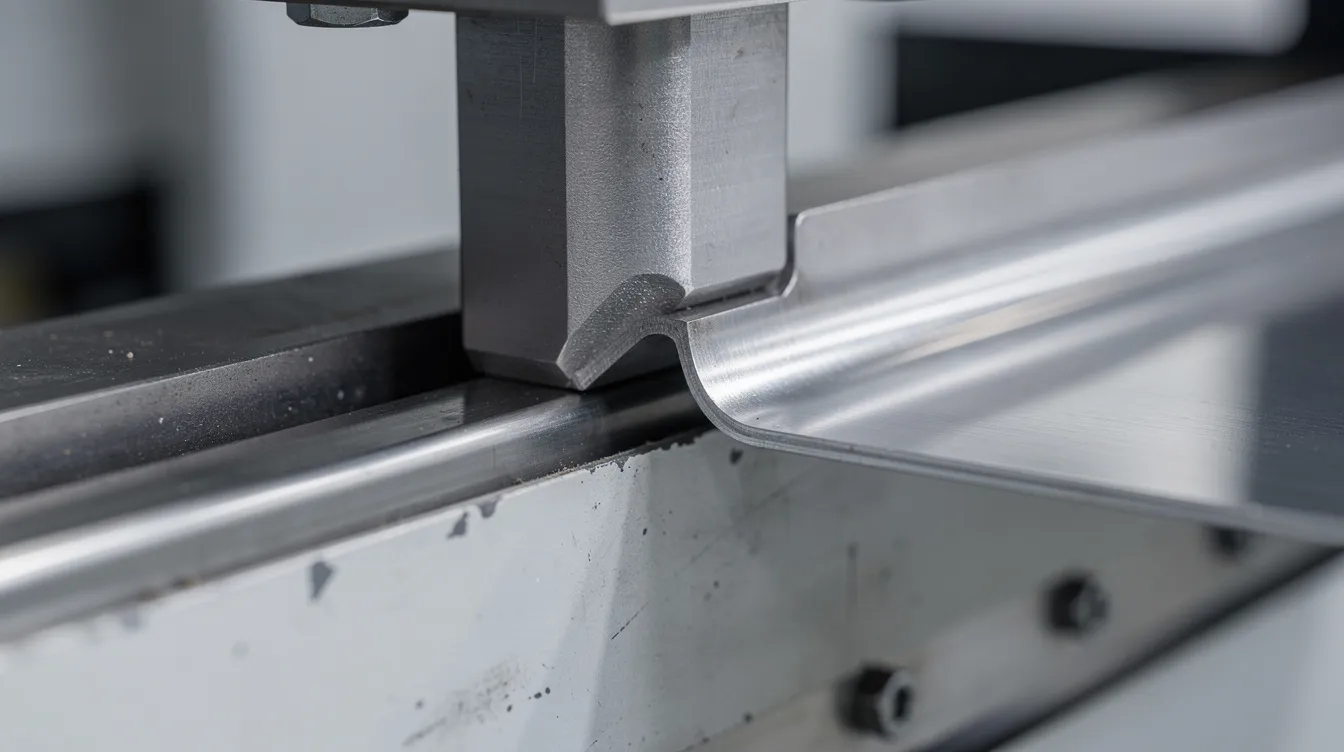
Not every metal bends the same way. Ductility and strength are key factors that determine which alloys are suitable for bending, what minimum radius you can achieve, and which bending method works best. Materials with high ductility are generally best for bending. Here’s how the most common alloys compare:
-
Mild steel (Q235, 1010, cold-rolled) – Yield ~200–250 MPa, elongation 20–30%. Mild steel is commonly used due to its excellent formability. Minimum inside radius as low as 0.5–1× thickness. Low springback, ideal for air bending.
-
304 stainless steel – Yield ~215–290 MPa (annealed), elongation ~40–60%. Stainless steel requires more force to bend due to work hardening. Recommended minimum radius of 1–2× thickness. Higher springback.
-
316L stainless – Similar to 304 but with improved corrosion resistance. Slightly lower yield in annealed condition; bend radii constraints remain comparable.
-
5052-H32 aluminum – Yield ~193 MPa, elongation 12–18%. Excellent formability and higher fatigue strength (~120 MPa). Inside radius of 1× thickness is generally achievable. Aluminum is lightweight and highly malleable for bending, making it a preferred choice for enclosures and panels. Aluminum is commonly used in metal bending due to its malleability.
-
6061-T6 aluminum – Yield ~270 MPa, elongation ~10–12%. Much stronger but less ductile in the T6 temper. Requires larger bend radii of 2–4× thickness to avoid cracking. May need local annealing along the bend zone.
-
Copper – A soft metal with high elongation. Copper is easily bent and highly conductive, making it ideal for electrical applications. Grain direction is less problematic except in heavily cold-worked conditions.
-
Brass – Elongation 30–45%. Brass is favored for its aesthetic appeal and ease of fabrication. Tight radii achievable in annealed tempers.
-
High-strength steels (spring steels, boron steels) – Yield >500 MPa, limited elongation. Minimum bend radius increases with material hardness. Often require bottoming, coining, or hot forming.
Bending methods are chosen based on material type and thickness. Softer alloys suit air bending; harder grades demand bottoming or coining for consistent results.
Key Design Parameters: Bend Radius, Force, and Allowance
The bend radius is the single most important geometric parameter in a bending operation. Too small an inside radius concentrates stress on the outer fibers, risks cracking, and degrades surface appearance. Too large a radius wastes material and may create clearance issues in assemblies.
A common rule of thumb is that bend radius should equal at least the sheet thickness (R/T ≥ 1). This works well for mild steel and soft aluminum like 5052, but it fails for high-strength steels, thick plate, and hard alloys like 6061-T6 where R/T must be 2–4× or more. The bend radius must increase with metal thickness, and bend radius increases with metal thickness as a general rule to maintain structural integrity.
Bending force depends on metal type and thickness. Force required is influenced by the material’s tensile strength, the thickness squared, bend length, and die opening width. Bending requires more force for thicker metals than for thinner ones – thicker metals need more force to bend successfully. For reference, CNC press brakes can exert over 100 tons of force, with 80–160 ton machines handling 3–6 mm steel sheet in typical OEM work. Thickness and material properties critically affect bending outcomes, and material thickness influences the effectiveness of bending methods across the board.
Bend allowance and bend deduction determine how the flat pattern translates to the finished part. Stretching in the bend region changes the effective length of each flange, and these values must be compensated in the CAD model. Anebon uses software-driven bend tables validated by actual production trials, adjusting K-factor values from theoretical defaults to match real tooling and material behavior.
Designer mini-checklist:
-
Confirm minimum inside bend radius based on alloy, temper, and thickness
-
Verify bending force against available press brake tonnage
-
Calculate flat pattern length using correct bend allowance for your material
-
Specify die opening width (typically 6–8× thickness for mild steel, 8–10× for stainless)
-
Discuss tolerance requirements with your supplier early
Grain Direction, Springback, and Fatigue in Bent Metal
Grain direction is created during rolling and has a measurable impact on bendability. Bending with the grain requires less force than across the grain, but bending parallel to grain increases the risk of surface cracking – especially in less ductile materials or hard tempers. For example, 3 mm 304 stainless bent parallel to grain may need a radius of 1.5–2× thickness to avoid cracking, while the same material bent perpendicular to grain can often achieve 1× thickness.
Localized stress can limit the inside bend radius. At the outside of the bend, fibers stretch; at the inside, they compress. Sharp notches, laser-hardened edges, burrs, or punched holes too close to the bend line act as stress risers and can cause fractures. Pay close attention to edge condition before any bending operation.
Springback must be compensated during bending to achieve the desired angle. Springback can cause deviations in the final bend angle, and materials like high-strength steel and aluminum exhibit greater elastic recovery. To compensate, operators may overbend – for instance, bending to 92° to achieve a final 90° desired bend angle – or use bottoming/coining tooling requirements that mechanically lock in the angle.
Bending fatigue occurs when metal is bent back and forth repeatedly. Micro-cracks initiate at the outer radius and propagate with each cycle, eventually causing fracture. This differs from failure in paper or wood fibers because metal fatigue is driven by crystallographic slip and dislocation accumulation at the grain level.
Rules of thumb for designing around grain and springback:
-
Bend perpendicular to grain direction whenever tight radii or hardened tempers are involved
-
Maintain inside radius at least 1× thickness for mild steel; increase for harder alloys
-
Keep holes and slots at least 2–3× thickness away from the bend line
-
Overbend or use bottoming/coining for springback-prone materials
-
Specify wide V-die openings and optimized punch nose radius to reduce peak stress
Different Types of Metal Bending Processes
There are different types of metal bending processes, and the right choice depends on material type, thickness, required precision, production volume, and geometry complexity. Common methods for bending metal include air bending, bottoming, and coining, but several other methods serve specialized needs.
-
Air bending – Sheet contacts only punch and die edges; angle set by punch stroke depth. Highest flexibility, lowest force, moderate tolerance.
-
Bottoming – Material pressed into V-die until it conforms to die geometry. Better repeatability, reduced springback, higher force.
-
Coining – Extreme pressure permanently deforms the bend zone. Highest precision, highest tonnage, greatest tool wear.
-
Roll bending – Rolling uses a series of rollers to create large-radius curves, used for tanks, beams, and cylindrical shapes.
-
Three-point bending – Central punch with adjustable supports for thick plate or structural components requiring tight angle control.
-
Folding – Sheet clamped on a beam; blade rotates to form the bend. Ideal for large panels with low surface-marking risk.
-
Wiping – Flange clamped and wiped around a form block. Fast cycle but higher risk of scratching.
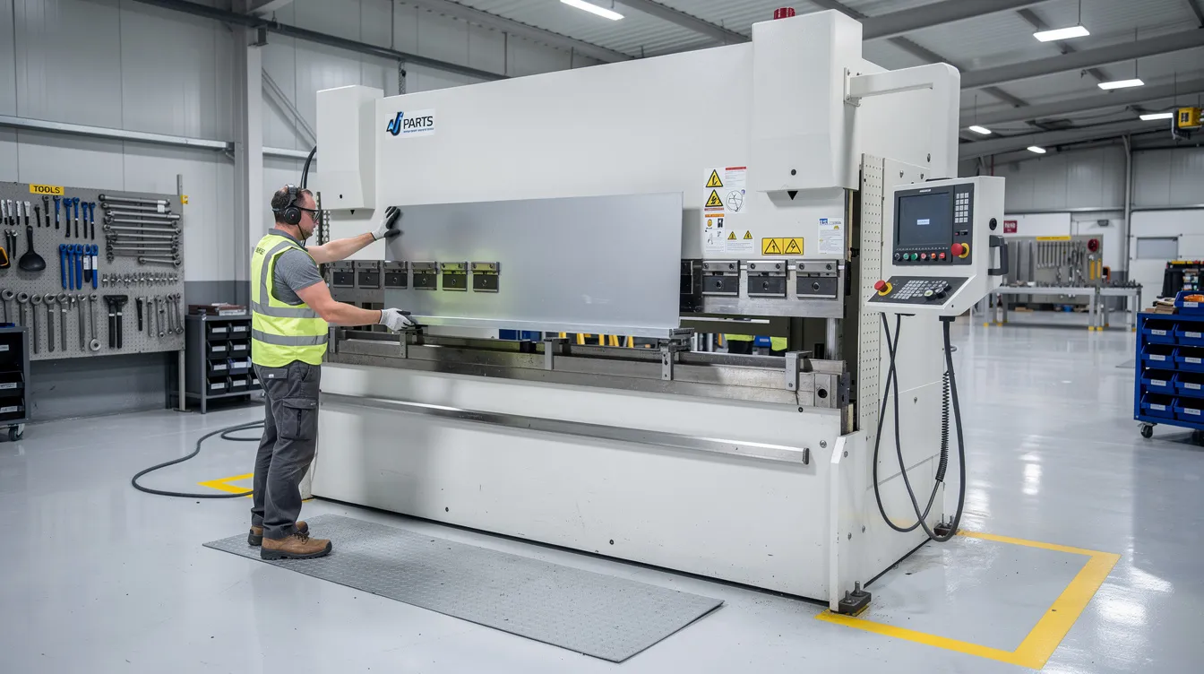
Press brakes are the primary machine for bending metal in precision sheet metal fabrication, and Anebon uses CNC press brake bending as the backbone of its forming cells. For special geometries or complex shapes, various methods including roll bending or folding may be recommended.
Press Brake Bending: Air Bending, Bottoming, and Coining
A press brake is a CNC hydraulic or electric machine consisting of an upper punch and a lower die that form bends along a straight axis, with typical working lengths of 1–3 meters. Press brakes can exert forces over 100 tons for bending heavy-gauge material.
Air bending offers the highest flexibility for creating various angles by adjusting punch depth. The sheet touches only the punch tip and die edges, meaning one tool set can produce multiple bend angles. Tolerance is generally ±0.5°, and the force required is the lowest among press brake methods. The tradeoff is greater springback.
In bottoming, the material is forced into the V-die until it fully conforms to the die angle. This demands 2–5× more force than air bending but delivers better repeatability and significantly reduced springback. Tool shape and die geometry directly determine the final angle.
Coining requires extreme pressure but offers high precision. The punch presses the material so forcefully that it thins and permanently deforms throughout the thickness. Coining minimizes springback but is energy intensive due to high tonnage requirements. It’s typically reserved for applications where angle tolerance must be extremely tight or where hardened materials resist other methods.
Modern CNC press brakes with angle measurement systems and servo-driven backgauges achieve angle precision of ±0.3° and position repeatability of ±0.1–0.2 mm, enabling consistent results across production runs.
Quick comparison:
-
Air bending – Least force, most flexible, largest springback
-
Bottoming – Moderate force, higher precision, reduced springback
-
Coining – Highest force, finest precision, lowest springback, greatest tool wear
Three-Point Bending, Folding, and Wiping
Three-point bending uses a central punch pressing the workpiece against two adjustable bottom supports. By varying the support span, operators can precisely control the bend angle and compensate for variation in material thickness. Three-point bending achieves bend angles with 0.25-degree precision, making it valuable for aerospace or structural components where ultra-tight tolerances are specified.
Folding clamps the sheet on a beam and rotates a folding blade upward or downward to form the bend. This method is ideal for large panels such as cabinet doors and machine covers, with low risk of surface marking since the tool shape doesn’t press directly into the material face.
Wiping clamps one flange and wipes the protruding section around a form block. It’s faster than folding but carries higher risk of surface scratching and tooling marks, making it less suitable for cosmetic parts.
When to choose each:
-
Three-point bending: thick plate, tight angle tolerances, prototype or low-volume structural parts
-
Folding: large flat panels, minimal secondary finishing, edges that must stay pristine
-
Wiping: speed-critical production, non-cosmetic flanges, tangential edge requirements
Hot Forming vs Cold Forming: When to Use Heat
Cold forming – bending at room temperature – covers the vast majority of sheet metal fabrication. It offers tighter dimensional control, simpler equipment, and no microstructural changes. Most parts Anebon produces are formed using controlled cold forming on CNC press brakes.
Hot forming heats the material to improve ductility and reduce the force required. For steel, typical hot forming temperatures range from 870–925°C (1,600–1,700°F), which is well below the melting point of the alloy but high enough to significantly improve formability. Benefits include reduced cracking and the ability to achieve tighter radii in high-strength steels. Drawbacks include scale formation, decarburization, and dimensional control challenges. Bending processes can generate significant energy usage, and hot forming amplifies this.
For aluminum, local annealing along the bend line can soften hard alloys like 6061-T6, but operators must pay close attention to temperature to avoid strength loss from over-aging.
Consider hot forming when:
-
Material hardness or strength prevents acceptable cold bend radii
-
Extreme bending angles may lead to metal deformation or fracture at room temperature
-
Part geometry demands radii smaller than cold forming allows
-
Volume justifies the added cost and thermal process complexity
-
The application tolerates post-forming scale or requires subsequent heat treatment
Tools and Equipment: Bending Tools Used by Anebon
The right bending tools determine whether a part meets spec or ends up as scrap. Here’s what Anebon’s fabrication cells typically deploy:
-
V-dies – The workhorse. Die opening widths of 6×–12× material thickness, with narrower openings producing tighter radii at higher force, and wider openings reducing tonnage but increasing radius.
-
Punches – Standard, goose-neck (for clearance on deep flanges), and radius punches for specific profiles.
-
Backgauges – Servo-driven positioning systems for repeatable placement of the workpiece before each bend.
-
Hem dies – For folding edges over to create stiffened, safe-to-handle edges.
-
Offset tooling – Enables compound bends or Z-profiles in a single stroke.
-
Auxiliary equipment – Radius gauges, angle measurement sensors, protective pads for finished surfaces, and fixtures for complex multi-bend parts.
Different die opening widths affect bend radius, required tonnage, and cracking risk. Anebon’s CNC press brakes integrate with laser cutting upstream and support offline programming directly from 3D CAD models.
From Flat Pattern to Bent Metal: Typical Manufacturing Process
Every metal bent part follows a predictable path from design to delivery. Understanding each step helps OEM customers specify parts that are easier – and cheaper – to produce.
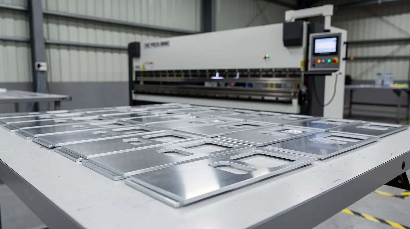
The flat pattern is generated from the 3D model using bend allowance values or bend tables calibrated for each material and thickness combination. Laser cutting improves bending precision by providing tight tolerances on edge positions and feature locations. Multiple bends are then sequenced on the press brake to avoid collisions between flanges and the machine, generally forming interior features first and larger flanges last.
Step-by-step checklist:
-
DFM review – Evaluate geometry for manufacturability, minimum radii, hole-to-bend distances
-
Flat pattern design – Develop 2D blank from 3D model with correct bend allowance
-
Laser cutting – Cut flat blank with tight feature locations and clean edges
-
Deburring / edge prep – Remove sharp edges to reduce cracking risk during bending
-
Bending – Execute bend sequence on CNC press brake with in-process angle checks
-
Inspection – First-article measurement of angles, radii, and critical dimensions
-
Finishing / assembly – Powder coating, anodizing, plating, hardware insertion as required
Design Guidelines and Practical Tips for Bending Metal
Good design decisions made before cutting a single blank save time, money, and frustration on the shop floor. Here are actionable rules to follow when designing bent parts:
-
Maintain minimum inside bend radius based on material type and temper – at least 1× thickness for mild steel, 2–4× for hardened aluminum or high-strength steel
-
Keep holes and slots at least 2–3× material thickness away from the bend line to prevent distortion
-
Avoid flanges narrower than 3–4× thickness, which are difficult to support in the die
-
Bend perpendicular to grain direction when possible, especially for tight radii in different materials
-
Standardize material thickness across parts in an assembly to simplify tooling and reduce setup cost
-
Specify realistic tolerances – sheet metal bending can produce parts with tight tolerances of ±0.1 mm on critical features, but ±0.5 mm on flange lengths is more typical and cost-effective
-
Account for springback compensation in your tolerance stack-up, especially for high-strength alloys
-
Discuss achievable tolerances with your manufacturer early to avoid over-specifying
Pre-quote checklist for engineers:
-
All bend angles and inside radii
-
Material specification (grade, temper, thickness)
-
Surface finish requirements (pre- or post-bend)
-
Annual volume estimate
-
Critical dimensions that must be held after bending
-
Any special tooling requirements or secondary operations
Advantages and Limitations of Bent Metal Parts
Advantages:
-
Lightweight parts with high stiffness achieved through geometry (flanges, ribs) rather than material mass
-
Cost-effective vs machining solid blocks – metal bending is cost-effective for low to medium quantities
-
Reduced part count: a single formed part can replace multiple machined and welded components, eliminating fasteners and weld distortion
-
Fast setup for small-to-medium production runs with flexible tooling changes
-
Broad application range: common applications for metal bending include automotive body parts and HVAC ductwork, plus brackets, enclosures, chassis frames, guards, and panels across the automotive industries, robotics, medical, and electronics sectors
Limitations:
-
Tight radii in thick or hard materials are often impossible or very costly to achieve
-
Springback causes angle variation and can require multiple passes or more expensive tooling
-
Extreme bending angles may lead to metal deformation or fracture, particularly against grain
-
Each bend introduces tolerance stack-up – multi-bend parts require careful process planning
-
Surface coatings or finishes can crack or scratch during the bending operation
-
Bending processes can generate significant energy usage, especially with coining or hot forming
-
Complex shapes with deep draws, pockets, or compound curvature still require stamping, deep drawing, or machining
Metal Bending at Anebon Metal Products Limited
Anebon handles sheet metal bending across a full range of different materials – aluminum, stainless steel, carbon steel, copper, brass, and specialty alloys – in thicknesses from 0.3 mm to 10 mm. Our CNC press brakes, integrated with fiber laser cutting and CNC machining, allow us to deliver complete OEM assemblies, not just individual bent parts.
Quality controls during bending include first-article inspection, in-process angle checks with calibrated gauges, and final inspection per ISO 9001:2015 procedures. We serve overseas OEMs in robotics, industrial machinery, medical devices, and electronics, producing everything from battery enclosure frames to precision sensor brackets with consistent results across production lots.
If you’re designing parts that need to be formed from flat sheet into a reliable, repeatable new shape, we can help you determine the right approach. Send your 2D/3D drawings to Anebon for DFM feedback and a fast, competitive quote – and let us show you why precision metal bending starts with the right fabrication partner.