Understanding How Does CNC Work: A Simple Guide to CNC Machining
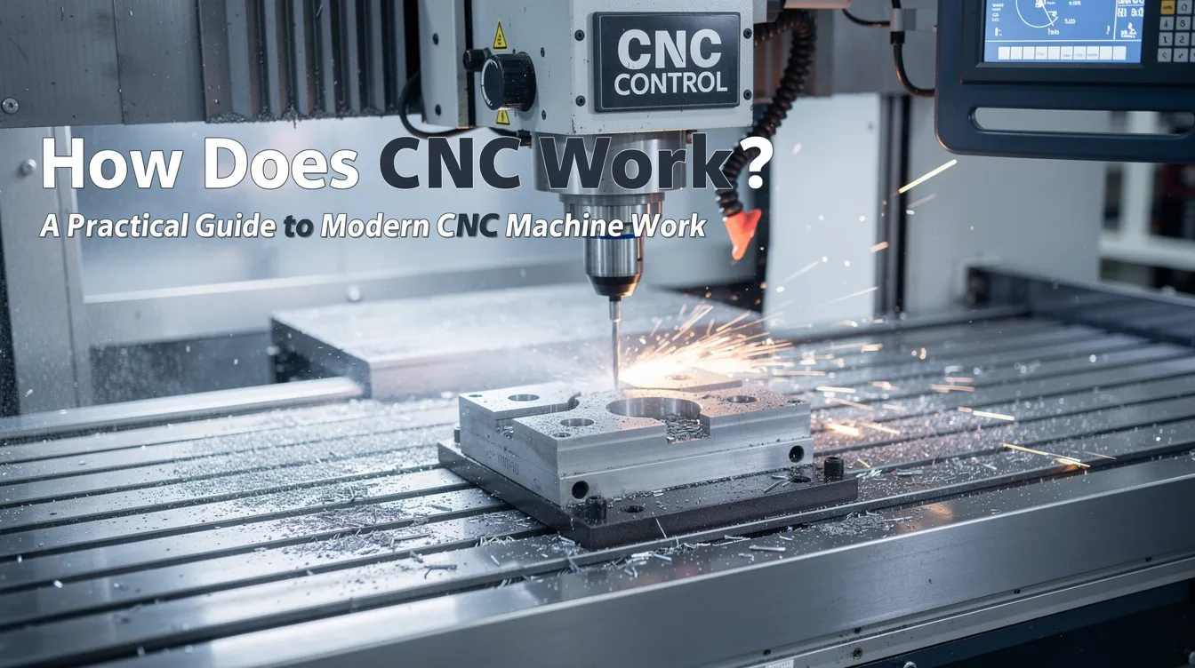
How Does CNC Work? A Practical Guide to Modern CNC Machine Work
If you design parts for a living, you’ve almost certainly sent a CAD file to a machine shop and received finished components back. But what actually happens between uploading that file and unboxing precision parts? This guide breaks down how CNC machining work turns digital geometry into physical metal and plastic components-covering the machines, the code, the motion control, and the real-world decisions that determine whether your parts come back right.
Quick Answer: How a CNC Machine Works
A cnc machine follows a digital cnc program-written primarily in g code-to move cutting tools along X, Y, and Z axes (and sometimes rotary axes) with micron-level precision. The controller reads each line of the program, commanding servo motors to position the tool, set spindle speeds, control feed rates, and manage coolant. The result is a subtractive manufacturing process: a cutting tool removes material from a solid block of metal, plastic, or other stock until what remains matches the original 3D CAD model.
What makes this process reliable for production is closed-loop control. CNC machines use a closed-loop system for guidance with precision and repeatability-feedback encoders continuously compare commanded position against actual position and correct errors in real time. This is why cnc machines operate with tolerances within 0.025 mm as standard, and precision shops can hold even tighter. At Anebon, for example, we routinely deliver OEM parts as tight as ±0.002 mm on critical features using high-end equipment, rigorous calibration, and ISO-certified quality systems.
CNC machining differs from laser cutting and additive manufacturing (3D printing) in that it is purely subtractive-but it can be combined with those processes within broader manufacturing workflows when the part geometry or volume calls for it. CNC machining can produce parts up to 100 times faster than manual methods, and the machines operate continuously without fatigue, making them the backbone of modern precision manufacturing.
What “CNC” Means in Manufacturing
CNC stands for Computer Numerical Control. The term describes any computer controlled machine that uses numeric coordinates, speeds, and coded instructions-rather than handwheels, levers, or manual machining-to control machine tool functions and axis movement. Understanding what cnc stands for computer numerical control helps clarify that the “numerical” part refers to the math: every position, feed rate, and spindle speed is a number the controller interprets.
The concept of numerical control dates back further than most engineers realize. CNC machining was invented in 1949 by John Parsons at MIT, who developed a method for using punched cards to control machine movements for helicopter blade production. Those early NC machines evolved through analog tape readers in the 1950s–1960s, then into the digital controllers that power modern cnc machines today. The first cnc machines were essentially retrofitted manual lathes and mills, but the shift from tape to computer control unlocked the programmability, speed, and repeatability that define cnc technology now.
It’s worth distinguishing two things: a cnc machine is the physical hardware (frame, axes, spindle, controller, motors), while the cnc machining process is what you do with that hardware-designing, programming, and executing cuts. CNC machining can process metals, plastics, and wood, as well as materials like granite and ceramics. CNC machines can cut through soft and hard materials equally, making them versatile across nearly every manufacturing industry.
At Anebon, we apply cnc technology across milling machines, cnc lathes, wire edm, and other cnc machine tools for precision metal fabrication. This range lets us serve overseas OEM clients in industries from aerospace to electronics with a single supplier relationship.
Core CNC Process: From CAD File to Finished Part
Every cnc manufacturing process follows the same high-level flow, regardless of whether you’re milling an aluminum housing or turning a titanium shaft:
Design → CNC Programming → Setup → Machining → Inspection
The CNC process includes design, programming, setup, and execution. CNC operation involves a digital-to-physical workflow that automates processes from the first line of code to the last inspection measurement. Here’s what happens at each stage.
1. CAD Model Creation
CNC machining starts with a CAD model creation. Engineers use cad software to create 2D or 3D models of desired parts, specifying every critical dimension, tolerance, and surface finish. Common computer aided design cad platforms include SolidWorks, CATIA, Siemens NX, and Fusion 360. The key is providing the right level of detail: which surfaces are critical for fit or sealing, which tolerances are functional versus cosmetic, and what material the part will be made from.
Over-tolerancing non-critical features is one of the fastest ways to drive up CNC costs. Define tight tolerances only where the part’s function demands them.
2. CAM Programming
Computer aided manufacturing cam software translates the CAD geometry into toolpaths the machine can execute. CAM software converts CAD models into CNC programming code, commonly G-code and M-code. The programmer selects cutting strategies (roughing, finishing, drilling, threading), defines tools, and sets parameters like step-over, depth of cut, spindle speed, and feed rate. The cam software then generates the cnc programs and runs them through a post-processor to output controller-specific code-whether the machine speaks Fanuc, Siemens, or Heidenhain.
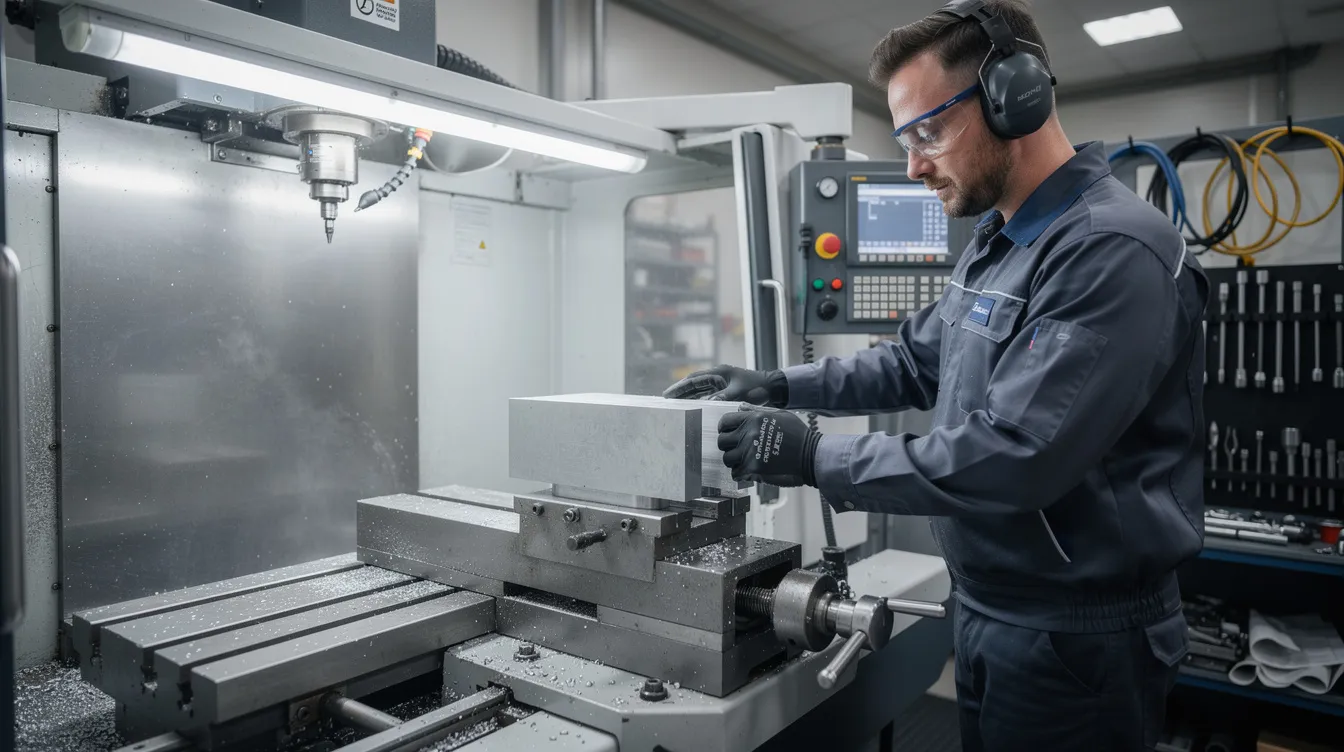
3. Machine Setup
During setup, a cnc machine operator or cnc machinists select raw stock material, mount it using workholding devices that secure raw materials to prevent movement during cutting, set work offsets (defining the machine’s zero point), load cutting tools, and calibrate tool length and diameter offsets. Environmental factors-shop temperature, machine warm-up-also matter for precision work.
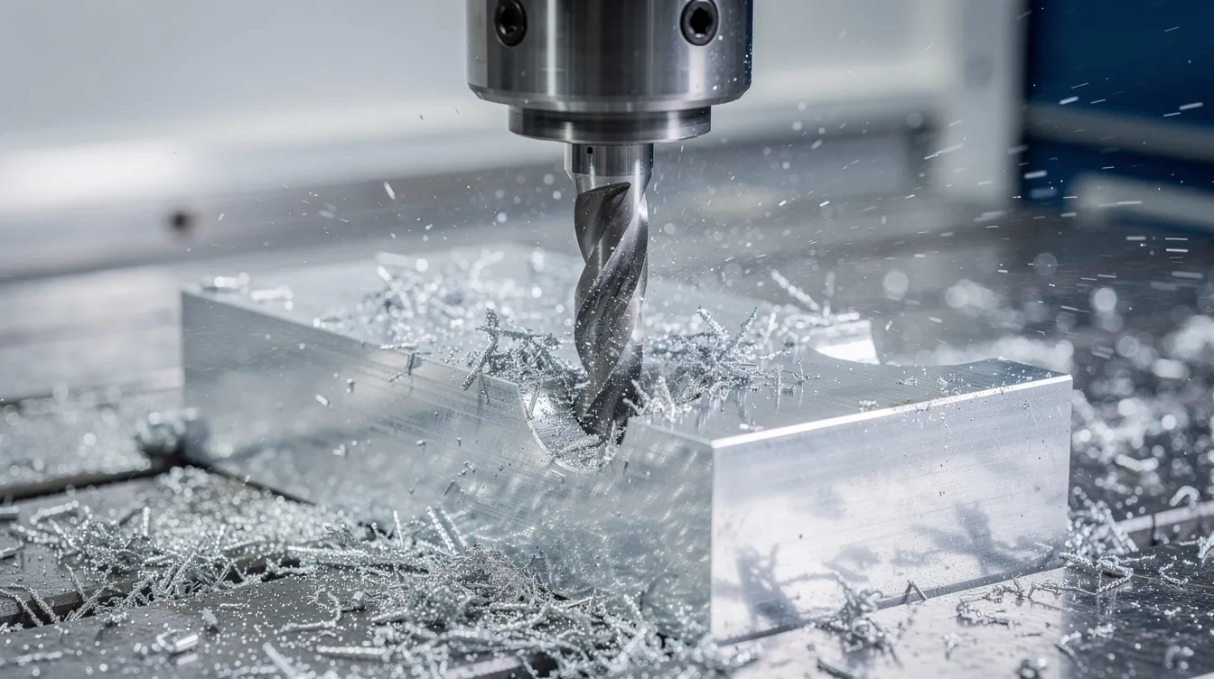
4. Machining Cycle
The controller reads the g code line by line. Rapid moves position the tool, then cutting moves execute at programmed feed rates while the spindle rotates the tool (or workpiece, in turning). CNC machines handle tool changes and speed regulation automatically without operator intervention. The motion control system-driven by closed-loop servo systems-ensures axes track the commanded path precisely, compensating for deflection, backlash, and thermal drift.
5. Inspection
At Anebon, we run both in-process and post-process inspection. In-process probing catches drift before it scraps parts. Post-process inspection with precision gauges, micrometers, and coordinate measuring machines (CMM) verifies that every feature meets drawing specifications. For regulated industries like medical devices and aerospace, full traceability and material certificates are standard.
Positioning Control: How CNC Machines Move So Accurately
Positioning control is the heart of cnc machining work. It determines where the cutting tool is in 3D space at every millisecond of the cut-and how accurately the machine can return to that same position thousands of times.
The Coordinate System
CNC machines operate on a Cartesian coordinate system to define tool movement. For a typical cnc milling machine, that means three linear axes: X (left-right), Y (front-back), and Z (up-down). CNC mills typically operate on three axes: X, Y, and Z. Four- and five-axis machines add rotary axes (A, B, or C) that tilt or rotate the workpiece or spindle, enabling complex machining tasks on multiple faces in a single setup.
Absolute vs. Incremental Coordinates
G-code commands control machine movement along X, Y, and Z axes using either absolute coordinates (every position referenced from a fixed origin) or incremental coordinates (each move relative to the current position). Before cutting starts, the operator sets the workpiece zero using work offsets (G54, G55, etc.), which define the part’s reference frame so the same program can be reused across setups or fixtures.
Closed-Loop vs. Open-Loop Control
Industrial metal cutting cnc machines almost always use closed-loop servo systems. Many CNC machines use sensors for closed-loop feedback to ensure precise tool positioning. Here’s the contrast:
|
Feature |
Closed-Loop (Servo) |
Open-Loop (Stepper) |
|---|---|---|
|
Feedback |
Encoders continuously report position |
No position feedback |
|
Error correction |
Real-time compensation |
None-missed steps accumulate |
|
Typical use |
Industrial CNC mills, lathes, EDM |
Hobby machines, cnc routers |
|
Precision |
Micron-level |
Adequate for non-critical work |
Drive systems include servo or stepper motors that effectuate the movement of the cnc tools along each axis. In commercial cnc machinery, servo motors drive precision ball screws that convert rotary motion to linear motion with minimal backlash. Linear guideways provide smooth, rigid movement. High-resolution encoders (often sub-micron) feed position data back to the controller, and backlash compensation algorithms correct any remaining mechanical play.
High-end equipment and disciplined positioning control are critical for the tight-tolerance OEM parts Anebon has been producing in Dongguan since 2010. Combined with thermally stable environments and regular machine calibration, this is how we consistently hold ±0.002 mm on critical features.
CNC Programming: G-Code, M-Code, and Toolpaths
CNC programming is the “language” that tells cnc machines exactly how to move, cut, and change tools. Without it, even the most advanced cnc machinery is just expensive metal sitting on a shop floor.
G-Code Fundamentals
G-code is the primary programming language for CNC machines. The ‘G’ in G-code stands for Geometry, reflecting that these commands define geometric movements. G-code is generated from CAD models for CNC machining-specifically, it’s the output of the CAM stage described earlier. G-code includes commands for spindle speed and tool movement, coolant activation, and tool changes.
Here are the most common commands every engineer should recognize:
|
Code |
Function |
Example |
|---|---|---|
|
G00 |
Rapid positioning (no cutting) |
Move tool quickly to start point |
|
G01 |
Linear interpolation (cutting) |
Straight-line cut at specified feed |
|
G02 |
Circular interpolation (CW) |
Mill a clockwise arc |
|
G03 |
Circular interpolation (CCW) |
Mill a counterclockwise arc |
|
M03 |
Spindle on (clockwise) |
Start spindle at programmed RPM |
|
M05 |
Spindle stop |
Stop spindle rotation |
|
M08 |
Coolant on |
Activate flood coolant |
|
M30 |
Program end and rewind |
Reset program to start |
Modal codes (like G01) stay active until overridden. Non-modal codes execute once. Feed rates (F values) and spindle speeds (S values) are specified inline, giving the controller everything it needs to execute each motion.
CAM-Generated Toolpaths
In practice, cnc machinists rarely write g code by hand for complex parts. Computer aided manufacturing cam software automatically generates toolpaths for features like pockets, holes, threads, contours, and 3D freeform surfaces. The software accounts for tool geometry, material hardness, chip load, and machine limits, then runs the output through a post-processor tailored to the specific controller brand.
Safe Programming and Simulation
Pre programmed computer software simulation is a critical safety step. Before running any new program on the machine, programmers simulate the toolpath to detect collisions between the tool, fixture, and workpiece. Clearance planes, retract heights, and soft limits prevent overtravel. Skipping simulation risks tool breakage, machine crashes, and scrapped parts.
At Anebon, our engineering team goes further: we often optimize customer-supplied CAD for manufacturability (DFM) and adjust toolpaths to balance cycle time, tool life, and surface finish-catching costly design issues before the spindle ever turns.
Main Types of CNC Machines and What They Do
The phrase “types of cnc machines” covers a broad family of machine tools, each suited to particular geometries, materials, and production requirements. Here are the major categories.
CNC Milling Machines
Cnc mills use rotating cutting tools to remove material from a stationary workpiece. A standard 3-axis cnc milling machine handles prismatic parts-housings, brackets, manifolds, plates with pockets and holes. Four- and five-axis machining centers add rotary axes, enabling the tool to approach the workpiece from virtually any angle. This is essential for creating complex shapes like aerospace brackets, turbine blades, and impellers in a single setup. At Anebon, our 5-axis capability lets us produce complex aluminum parts and titanium components that would otherwise require multiple setups and fixtures.
CNC Turning Centers and Lathes
CNC lathes are primarily used for producing cylindrical components. In a cnc turning machine, the workpiece rotates while a stationary cutting tool shapes the outside diameter, inside bore, faces, grooves, and threads. Unlike manual lathes, CNC turning centers execute complex profiles automatically with pre programmed software. Swiss-type lathes are a specialized subset: they feed bar stock through a guide bushing for exceptional concentricity on small, precise parts like medical fasteners and electronic connectors. A stationary cutting tool shapes material as the workpiece spins-this is why turning excels at diameter control.
CNC Routers
Cnc routers are lighter-duty machines designed for wood, plastics, composites, and soft metals like aluminum sheet. They share the same basic coordinate-driven motion as milling machines but have lower spindle power and frame rigidity. This makes them suitable for sign making, furniture components, and prototype enclosures, but not for heavy metal cutting or tight-tolerance production.
Electric Discharge Machines (EDM)
Electrical discharge machining-also called spark machining-uses controlled electrical discharges to erode electrically conductive materials. There are two main types of cnc EDM:
-
Wire EDM: A thin wire electrode cuts through the workpiece like a bandsaw made of electricity. Ideal for precise cutting of hardened tool steels, sharp internal corners, and intricate die profiles. Tolerances of ±0.002–0.005 mm are achievable.
-
Sinker EDM: A shaped electrode “sinks” into the workpiece to create cavities and complex 3D forms. Used extensively for mold and die work.
Electric discharge machines work exclusively with electrically conductive materials-metals and conductive alloys-and excel where conventional cutting tools can’t reach or where material hardness makes chip-removal impractical.
Other CNC-Controlled Cutting Processes
Several additional cnc processes use non-contact methods:
-
Laser cutting: CNC laser cutters can cut through various materials using focused laser beams. Excellent for sheet metal profiles and thin-gauge work.
-
Plasma cutting: CNC plasma cutters use a high-temperature plasma arc for cutting thick steel plate and structural shapes.
-
Waterjet cutting: CNC waterjet cutters use high-pressure water streams for cutting materials-including glass, stone, and composites-without heat-affected zones.
These are typically chosen for 2D profiling rather than 3D cavity work, which is where milling machines and turning centers dominate.
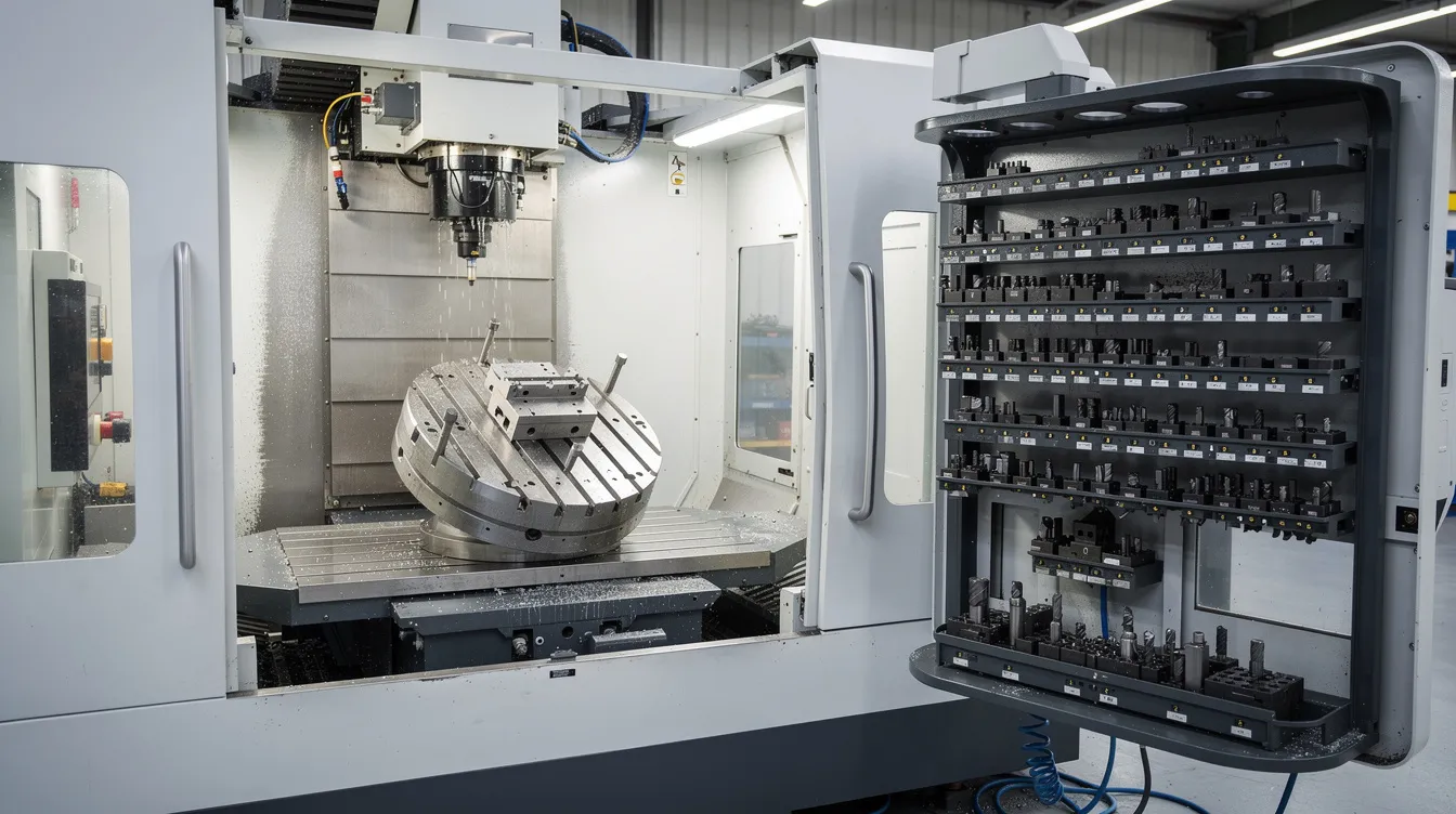
Inside a CNC Machine: Key Components and Their Roles
Let’s walk around a typical cnc milling machine or turning center and identify the components that make precise cutting possible.
Machine Bed, Table, and Enclosure
The machine bed is the foundation-a heavy, rigid casting (often cast iron or polymer concrete) designed to absorb vibration and resist deflection under cutting forces. The table sits on top, providing a flat surfaces mounting point for fixtures and workpieces. The enclosure contains chips, manages coolant spray, and protects the operator. Rigidity in these components directly affects achievable tolerances and surface finish.
Spindle and Toolholding
Spindles rotate at high speeds to enable the cutting process in CNC machining-from a few hundred RPM for large-diameter face mills to 30,000+ RPM for small end mills in high-speed machining. The toolholding system (collets, chucks, or toolholders like CAT, BT, or HSK tapers) grips the tool with minimal runout. Runout below a few microns is critical for precision OEM work; poor runout degrades surface finish and accelerates tool wear.
Axis Drives and Motors
Each axis has its own servo motor, ball screw (or linear motor), and linear guideway. Servo motors provide precise torque and speed control within the closed-loop system. Ball screws convert the motor’s rotary motion into linear travel with high efficiency and low backlash. Linear guideways constrain motion to a single direction with high stiffness. Together, these components let axes accelerate, decelerate, and position with micron-level accuracy.
CNC Controller and Operator Panel
The CNC controller is the brain. It reads cnc programs, interpolates multi-axis motion, manages spindle commands, monitors safety interlocks, and stores tool offset tables and work offsets. The operator panel and display let the cnc machine operator load programs, jog axes, set offsets, run diagnostics, and respond to alarms. Major controller brands include Fanuc, Siemens, Heidenhain, and Mitsubishi.
Auxiliary Systems
Modern cnc machines include several support systems that improve reliability and throughput:
-
Coolant delivery (flood, mist, or high-pressure through-tool) removes heat and chips from the cutting zone
-
Chip conveyors and augers clear swarf automatically
-
Touch probes measure part features and tool lengths in-machine, reducing manual measurement time
-
Temperature compensation algorithms correct for thermal drift in the spindle and frame during long production runs
These systems are what separate a production-ready machining center from a basic machine tool.
Typical CNC Machining Operations and Processes
Most parts are made using a combination of core CNC operations tailored to the part’s geometry and material. CNC machining automates the cutting and shaping of materials-here are the operations that make up the bulk of production work.
CNC Milling Operations
-
Face milling: Creating flat surfaces on the top of a workpiece using a large-diameter cutter
-
Contouring/profiling: Cutting the external shape of a part along 2D or 3D paths
-
Pocketing: Machining internal cavities-common in aerospace housings with thin ribs
-
Drilling and tapping: Creating holes and internal threads
-
3D surfacing: Sculpting freeform surfaces like turbine blades or medical implant geometries
In milling, rotary cutting tools spin against the workpiece, and the cutting tool removes material in successive passes. The cutting process uses rotating cutting tools at programmed speeds and depths to achieve the target geometry.
CNC Turning Operations
-
OD turning: Reducing outside diameter to specification
-
ID boring: Enlarging internal bores
-
Facing: Squaring up end faces
-
Grooving and threading: Cutting grooves, O-ring seats, and external/internal threads
-
Parting: Cutting finished parts off bar stock
In turning, a stationary cutting tool shapes the spinning workpiece. This is why cnc lathes excel at dimensional control on cylindrical features.
Specialty Processes
Anebon also supports 5-axis machining for complex freeform surfaces, EDM for hardened tool steels and intricate die cavities, and cnc grinding machines for critical surfaces requiring Ra values below 0.4 µm.
Secondary Treatments
The cnc manufacturing process often extends beyond chip removal. Finished parts frequently require deburring, anodizing, plating, painting, or heat treatment before they’re ready to assemble. Typical surface finish values:
|
Process |
Surface Roughness (Ra) |
|---|---|
|
Standard as-machined |
~1.6 µm |
|
Finish-machined |
~0.8 µm |
|
Ground |
0.1–0.4 µm |
Cycle Optimization
For overseas customers shipping containers of parts, cycle time matters. Strategies include grouping operations to reduce tool changes, minimizing air moves, using multi-axis machines to eliminate re-fixturing, and scheduling roughing and finishing passes efficiently. CNC machining can create objects a hundred times faster than manual methods-but smart programming is what captures that speed advantage in real production.
CNC Machining Compared to Other Manufacturing Processes
Engineers often weigh cnc machining compare factors against casting, molding, stamping, and additive when deciding how to produce a part. Here’s how the options stack up.
CNC vs. Additive Manufacturing
CNC is a subtractive manufacturing process; additive manufacturing builds parts layer by layer. Additive excels at internal channels, lattice structures, and low-volume complex geometries where material waste would be extreme with machining. But CNC wins on material properties (full-density metals), surface finish, tolerances, and hardness. For production-grade metal parts, CNC remains the standard.
CNC vs. Die Casting and Injection Molding
Die casting and injection molding are cost-effective for high volume production-but only after you’ve paid for tooling (often $5,000–$50,000+). CNC machining requires no hard tooling, making it ideal for prototyping, low-to-mid volumes, and high-precision features like bored holes and threaded ports that cast parts often can’t achieve without secondary machining. CNC machining can work with metals, plastics, and wood, as well as CNC machines can work with metal alloys, giving it broader material flexibility than most casting processes.
CNC vs. Sheet Metal and Laser Cutting
Sheet metal fabrication and laser cutting are preferable for thin-walled enclosures, brackets, and large flat profiles. But when parts need deep 3D cavities, tight bore tolerances, or complex geometries, milled or turned components are the better choice.
Choosing the Right Process
Anebon offers CNC machining, die casting, and sheet metal fabrication under one roof, enabling customers to choose the most cost-effective path per part and quantity. The decision matrix typically looks like this:
|
Factor |
Favors CNC |
Favors Casting/Molding |
Favors Sheet Metal |
|---|---|---|---|
|
Annual volume |
< 10,000 |
> 10,000 |
Any |
|
Tolerances |
Tight (±0.01 mm+) |
Moderate |
Moderate |
|
Geometry |
3D complex |
Near-net shape |
2D/bent |
|
Tooling cost |
None |
High |
Low–moderate |
|
Material range |
Very broad |
Limited alloys |
Sheet gauge |
Design engineers should weigh geometry, annual volume, material, and lead time when choosing between cnc processes and alternative manufacturing methods.
Why CNC Matters for Precision OEM Parts (and How Anebon Helps)
CNC machining is essential for producing high-precision parts across virtually every advanced industry. CNC machining is vital in the aerospace industry for precision parts-from structural brackets to flight-critical housings. CNC machines produce engine blocks and transmission housings in automotive manufacturing. CNC machining creates custom medical devices and surgical instruments with biocompatible materials. CNC technology is used for high-speed drilling of circuit boards in electronics. And CNC machining is essential for producing high-precision components in defense applications where failure is not an option.
The core advantages of cnc machining work for OEM buyers:
-
Tight tolerances: CNC machining achieves tolerances within 0.025 mm as standard, with precision features down to ±0.002 mm
-
Repeatability: CNC machining ensures consistent quality across thousands of parts
-
Material flexibility: Aluminum, titanium, stainless steels, engineering plastics, and more
-
Speed: CNC machining reduces production costs by minimizing labor hours, and large scale production runs benefit from unattended operation
-
Prototyping to production: The same machine and program can produce one part or ten thousand
Anebon Metal Products holds ISO 9001:2015 and ISO 14001:2015 certifications, providing the quality systems and traceability that regulated industries demand. Since 2010, we’ve exported precision metal and plastic parts from Dongguan to overseas design engineers and R&D teams across aerospace, medical, automotive, electronics, and robotics.
When should you engage your CNC supplier? Early-during design. Getting DFM feedback on tolerances, feature access, and material selection before freezing your CAD saves revision cycles, reduces scrap, and often cuts part cost by 15–30%.
Ready to get started? Share your CAD files with Anebon’s engineering team for a detailed quote and free DFM review. Whether you need CNC milling, turning, EDM, die casting, or sheet metal fabrication, we’ll recommend the most cost-effective path for your parts and volumes. Request a quote today.