Understanding C N C Machining: Processes, Benefits, and Applications
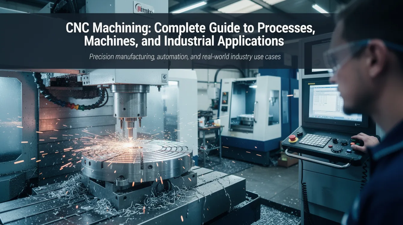
C N C Machining: Complete Guide to Processes, Machines, and Industrial Applications
CNC machining is one of the most important production technologies in modern manufacturing, enabling engineers to turn digital designs into physical parts with remarkable speed and precision. This guide covers everything from the fundamentals of how CNC machines work to advanced topics like 5-axis machining, material selection, and cost optimization-giving design engineers and procurement teams the knowledge they need to make better decisions.
What Is CNC Machining and Why It Matters Today
CNC machining is a subtractive manufacturing process in which pre-programmed computer numerical control software directs machine tools to remove material from a solid workpiece, producing precise metal and plastic parts. CNC stands for Computer Numerical Control, and the technology replaces manual machining with automated, digitally driven operations that deliver far greater accuracy, repeatability, and throughput.
CNC machining began in the late 1940s with NC machines developed for military and aerospace applications. In 1949, John T. Parsons created a CNC machine for helicopter blades, and MIT developed the first true numerical control machine in 1952. The introduction of computers in the 1960s transformed CNC machining into the versatile, software-driven manufacturing process we know today.
Here is why CNC machining matters across industries:
-
It uses computerized controls for precise manufacturing, supporting tight tolerances of ±0.002 mm.
-
High precision in CNC machining minimizes human error in part production.
-
CNC machining can significantly reduce labor costs by automating operations.
-
It allows for the production of complex geometries that are difficult to achieve with manual methods.
-
CNC machining offers exceptional repeatability and consistent part quality.
-
It is suitable for a wide range of materials-metals, plastics, and composites.
-
CNC machining allows for rapid prototyping and mass production from the same equipment.
Core CNC machining processes include CNC milling (cutting pockets, slots, and 3D surfaces with a rotating cutting tool), CNC turning on a CNC lathe (shaping cylindrical parts like shafts and bushings), CNC drilling (producing cylindrical holes in precise patterns), CNC routers (high-speed cutting of sheet and panel materials), and laser cutting (thermal cutting of flat sheet metal with focused beams).
Anebon Metal Products Limited is an ISO 9001:2015 and ISO 14001:2015 certified OEM partner based in Dongguan, China, specializing in precision CNC machining for overseas clients across aerospace, medical, automotive, electronics, and robotics sectors.
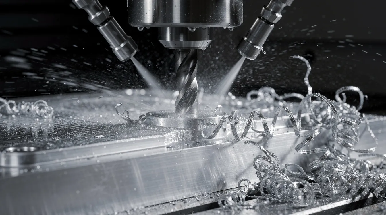
How CNC Machines Work: From Code to Cutting Tool
Understanding how CNC machining works starts with the machine itself and the code that drives it.
A CNC machine consists of several core components:
-
Machine bed: A rigid cast-iron or mineral-cast base that absorbs vibration and supports the entire structure.
-
Spindle: The rotating element that holds the cutting tool (in milling) or drives the workpiece (in turning).
-
Axes: Linear rails and ball screws provide motion along X, Y, and Z. Rotational axes (A, B, or C) add angular movement.
-
Servo motors: Precision electric motors that drive each axis with exact positional feedback.
-
Machine controller: The embedded computer or PLC that interprets G-code and coordinates all motion and auxiliary functions.
Axis CNC control determines what geometries a machine can reach:
-
2-axis: Motion in X and Z only (basic CNC lathe work).
-
3-axis: X, Y, and Z linear motion-the standard for most CNC milling.
-
4-axis: Adds one rotational axis for indexing or continuous rotation.
-
5-axis: Two rotational axes plus three linear axes, enabling complex parts in a single setup.
CNC machines can operate across three to five axes for precision, and the choice of configuration directly affects reachable geometries and cycle time.
G-code controls CNC machine movements and operations-linear moves, arcs, drilling cycles, and feed rates. M-code manages auxiliary functions in CNC machining such as coolant flow on/off, spindle start/stop, and tool changes. Together, they define every tool path the machine follows.
Here is a simplified G-code snippet showing a machine move to position and drill a hole:
G00 X10 Y20 Z5      ; Rapid move above workpiece
G01 Z-5 F150         ; Feed down to cutting depth
G81 X15 Y20 Z-10 R2 F200  ; Canned drilling cycle
M05                  ; Spindle stop
The machine code is generated by CAM software and tailored to the specific machine through a post-processor, so the same CAD model can drive a 3-axis mill, a 5-axis machining center, or a CNC lathe.
Step‑by‑Step CNC Machining Process
The CNC machining process follows a clear workflow from digital design to finished part. While CNC machining is highly automated, each step requires engineering judgement for tolerances, tooling selection, and fixture design.
-
CAD design: Engineers create or receive a 3D model with dimensions and tolerance callouts.
-
CAM programming: The CAD model is converted into machine-readable G-code, defining tool paths for every machining operation.
-
Machine setup: Operators load raw material, install cutting tools, set work coordinates, and verify fixtures.
-
Cutting and machining: The CNC machine executes the program-roughing, semi-finishing, and finishing passes per the programmed strategy.
-
Inspection and quality documentation: Inspection and finishing are critical steps after the machining process. Parts are measured against specifications and documented.
At Anebon, this process starts with an RFQ and includes DFM feedback before programming begins. First article inspection (FAI) validates dimensions before full production runs commence.
CAD Design: Turning Ideas into Machinable Geometry
CNC machining starts with designing parts in CAD software. Computer aided design (CAD) tools create the 2D or 3D models that define every dimension, geometric tolerance, and surface finish requirement a part needs.
Common CAD software used by OEM engineers and Anebon’s team includes SolidWorks, CATIA, and Siemens NX. Parametric, fully defined models ensure that CNC design intent is clear and unambiguous for downstream programming.
Design for Manufacturing (DFM) is where cost and quality are won or lost:
-
Maintain minimum wall thicknesses of 0.8 mm for metals and 1.5 mm for plastics to avoid deflection during cutting.
-
Use internal fillet radii that match standard end mill diameters-a 3 mm inside corner radius accommodates a 6 mm tool.
-
Avoid unnecessarily deep pockets; a depth-to-width ratio beyond 4:1 increases tool deflection and chatter.
-
Specify only the tolerances that function demands. Calling ±0.01 mm on every dimension inflates cost without adding value.
Export formats relevant to CNC machining include STEP, IGES, and Parasolid. A clean CAD file with no broken surfaces or undefined geometry prevents programming delays and reduces the risk of machining errors.
A common design mistake: specifying sharp internal corners. No end mill can produce a true 90° internal corner-always add a radius.
CAM Programming and Toolpath Creation
Computer aided manufacturing (CAM), as part of broader cnc software, bridges the gap between a CAD model and the physical cutting process. CAM software generates G-code from CAD models for CNC machines, using CAD data to create control programs and tool paths that translate geometry into precise motions for milling, turning, drilling, and cutting.
Inside the CAM environment, a programmer makes critical decisions:
-
Tool selection: End mills, drills, boring bars, or carbide inserts based on material and feature.
-
Cutting strategy: Roughing (high material removal rate, deeper step-down) versus finishing (light passes, higher spindle RPM, finer stepover for surface quality).
-
Feeds and speeds: Cutting speed, feed per tooth, and depth of cut are set based on material data-for example, finishing 7075 aluminum at 150–220 m/min surface speed with 0.03–0.10 mm feed per tooth.
-
Coolant strategy: Flood coolant, mist, or minimum quantity lubrication depending on material and operation.
Post-processors convert generic CAM output into machine-specific machine code for different controllers (Fanuc, Siemens, Heidenhain). This means the same CAD model can target a 3-axis VMC or a 5-axis machining center without re-programming from scratch.
CAD-CAM integration streamlines CNC machining workflows. Modern cam software includes built-in simulation that detects collisions between the cutting tool, fixtures, and machine bed before any real cutting begins-saving material, time, and tooling costs.
Key CNC Machining Processes (Milling, Turning, Drilling & More)
Different types of CNC machining are chosen based on part geometry, tolerance requirements, and production volume. CNC machines can perform multiple operations in one cycle, and selecting the right process for each feature is fundamental to efficient production.
The main CNC machining operations include:
-
CNC milling: Pockets, slots, flat surfaces, and complex 3D contours. CNC milling is the most prevalent CNC machining method.
-
CNC turning: External and internal cylindrical features-shafts, bushings, threaded components. CNC turning produces cylindrical parts using a rotating workpiece.
-
CNC drilling: Precise cylindrical holes, counterbores, and countersinks using a drilling operation with indexable or solid carbide drills.
-
Boring and tapping: Enlarging existing holes to tight tolerances and cutting internal threads.
-
CNC grinding: Achieves high-precision surface finishes on parts using a rotating grinding wheel, often as a secondary finishing operation.
Each process excels in specific applications. For a comprehensive guide to CNC machining techniques and applications, the key is matching the process to the feature-milling for prismatic shapes, turning for rotational symmetry, and grinding when surface finish below Ra 0.4 μm is required.
CNC Milling in Detail
CNC milling uses a rotating cutting tool that rotates against a stationary or moving workpiece clamped on a rigid machine bed. It is the most versatile of all types of CNC processes, capable of producing everything from simple flat surfaces to complex 3D aerospace components.
The differences between axis configurations matter significantly:
-
3-axis milling: The cutting tool rotates and moves in X, Y, and Z. Ideal for simple housings, plates, and brackets.
-
4-axis milling: Adds a rotational axis (typically A-axis) for indexed or continuous machining of features around a part’s circumference.
-
5-axis milling: Two rotational axes enable the tool to approach the workpiece from virtually any angle. Five-axis CNC machining allows for complex geometries in one setup, reducing setups and improving accuracy. 5-axis machining emerged as a significant advancement in CNC machining technology, and Anebon uses it for undercuts, impellers, medical implants, and complex housings.
Typical milling operations include face milling for flat datum surfaces, contouring for 3D profiles, pocketing for weight reduction, and high-speed machining of aluminum molds and structural parts.
Advantages of CNC milling at Anebon:
-
Tolerances down to ±0.002 mm on critical features.
-
Surface finish from Ra 1.6 μm (finish milling) down to Ra 0.4 μm with additional grinding.
-
Flexibility from rapid prototyping to full production runs.
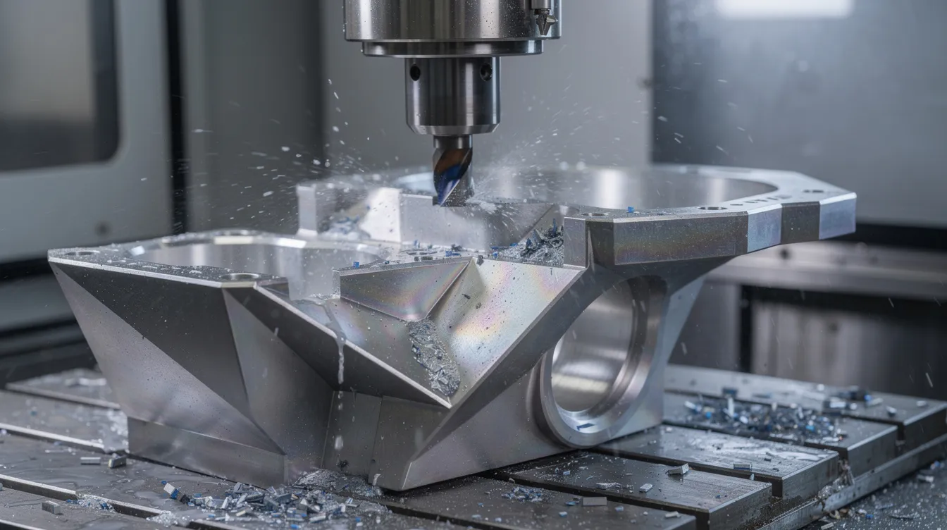
CNC Turning and CNC Lathes
A CNC lathe rotates the workpiece against stationary or live cutting tools to produce cylindrical parts such as shafts, pins, fittings, and valve bodies. The rotating workpiece is held in a chuck or collet, and the tool moves along X and Z axes to cut the desired shape.
Common turning operations include:
-
Facing: Creating a flat end surface perpendicular to the axis of rotation.
-
OD turning: Reducing the outer diameter to specification.
-
ID boring: Enlarging internal features to precise dimensions.
-
Grooving and parting: Cutting channels or separating finished parts from bar stock.
-
Thread cutting: Producing metric or inch threads for threaded components to exact pitch and class specifications.
Modern CNC lathes with multi-turret and live-tool capability combine turning and limited milling in a single setup, dramatically reducing cycle time and improving concentricity. Swiss machining takes this further for small-diameter, high-precision parts like medical pins and electronic connectors.
For a deeper look at CNC turning and milling and how they complement each other, consider how a stainless steel valve body can be OD-turned, bored, threaded, and cross-drilled in one clamping on a multi-axis CNC lathe-delivering high accuracy without multiple setups.
CNC Routers, Laser Cutting, and Other CNC Cutting Methods
CNC routers are high-speed, lower-rigidity machines designed for cutting wood, plastics, composite sheet materials, and softer metals. They differ from heavy CNC machining centers in spindle power and structural rigidity, but excel at large-format work like panels and enclosures.
CNC laser cutting uses focused laser beams for precise cuts in flat sheet metal. It is a thermal process ideal for profiles, slots, and cutouts in materials up to moderate thicknesses. For OEM sheet metal fabrication, Anebon often combines laser cutting for blank profiles with subsequent CNC machining for tolerance-critical features like bored holes and mating surfaces.
Other CNC cutting methods that complement traditional machining:
-
CNC water jet machining: Cuts materials using high-pressure water streams, often mixed with abrasive garnet. No heat-affected zone, suitable for heat-sensitive materials.
-
Plasma cutting: Fast cutting of thick steel plate, typically for structural or non-precision applications.
When to use what: laser cutting handles 2D profiles quickly and economically; CNC machining takes over when tight tolerances, 3D features, or critical surface finishes are required.
CNC Machines and Axis Configurations
Understanding what a CNC machining center is starts with knowing the common machine categories:
|
Machine Type |
Typical Axes |
Best For |
|---|---|---|
|
Vertical Machining Center (VMC) |
3 or 4 |
Flat parts, plates, housings |
|
Horizontal Machining Center (HMC) |
4 or 5 |
Box-shaped parts, multi-face machining |
|
CNC Lathe |
2 or 3 |
Shafts, bushings, cylindrical parts |
|
Mill-Turn Center |
5+ |
Complex turned-milled parts in one setup |
|
Gantry Mill |
3 to 5 |
Large aerospace panels and molds |
Modern CNC machines rely on a rigid machine bed (cast iron or mineral cast), precision linear guides, preloaded ball screws, and high-resolution servo motors to achieve the positional accuracy that tight tolerances demand. Machine adjustments like backlash compensation and thermal offset correction are handled automatically by the machine controller.
CNC machines can operate across three to five axes for precision, and the axis count directly determines which geometries a single setup can reach. A 5-axis machine can produce an aerospace blisk or turbine blade in one clamping, while a 3-axis mill handles simple housings efficiently at lower hourly rates.
CNC Machining Equipment, Tooling, and Workholding
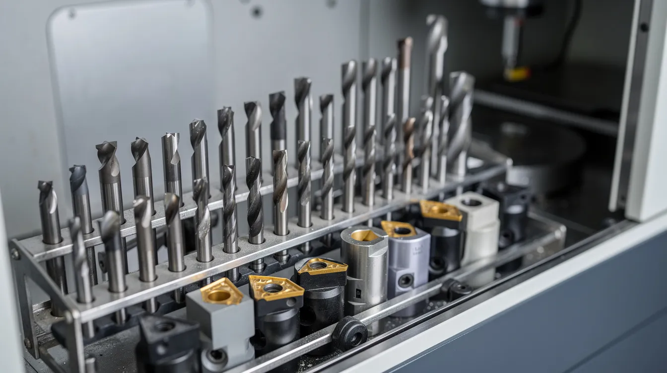
Beyond the machine itself, essential CNC machining equipment includes tool holders, cutting tools, in-process probes, coolant systems, and chip conveyors.
Cutting tools are the heart of every machining operation:
-
Carbide end mills: Solid carbide with 2, 3, or 4 flutes for milling aluminum through hardened steel.
-
Carbide inserts: Indexable multi point cutting tools for turning, facing, and boring-replaceable cutting edges reduce downtime.
-
Drills: Solid carbide or indexable drills for the drilling operation, with coatings like TiAlN or TiCN for extended life.
-
Coatings: TiAlN for high-temperature alloys, TiCN for steels, diamond-like carbon (DLC) for aluminum and non-ferrous metals.
Workholding directly affects achievable tolerances and surface finish:
-
Vises and chucks for standard clamping.
-
Collets for high-concentricity turning on a CNC lathe.
-
Custom fixtures and vacuum tables for thin or irregular parts.
Anebon uses modular fixture systems and custom jigs to cut setup times on repeat OEM orders, ensuring consistent quality and faster turnaround across production processes.
Materials for CNC Machining and Their Impact on Design
CNC machining can shape metals, plastics, and composites. Material choice directly influences cutting speed, tool life, achievable surface finish, and cost.
Metals:
-
Aluminum (6061, 7075): Aluminum is ideal for CNC machining due to its low cost, excellent machinability, and favorable strength-to-weight ratio. 7075-T6 offers tensile strength around 572 MPa but requires attention to residual stress and tool sharpness.
-
Stainless steel (304, 316, 17-4PH): Stainless steel is popular for its strength and corrosion resistance, though it machines at slower cutting speeds and increases tool wear.
-
Titanium (Ti-6Al-4V): High strength, low thermal conductivity-requires slow speeds, rigid setups, and heavy coolant flow.
-
Brass C36000: Favored for its machinability and corrosion resistance, producing excellent surface finishes with minimal burr.
-
Copper: Excellent conductivity but gummy chip behavior; sharp tools and proper chip evacuation are essential.
-
Inconel alloys: Maintain integrity at high temperatures and resist oxidation, making them critical for turbine and exhaust components-but extremely demanding on tooling with very low cutting speeds.
Plastics:
-
POM (Delrin): Excellent dimensional stability and machinability.
-
Polycarbonate: Known for its impact resistance and machinability, used widely in optical and electronics housings.
-
PEEK: High-performance engineering plastic for medical and aerospace applications; requires careful heat management.
-
ABS and Nylon: Cost-effective for prototyping; thermal expansion must be accounted for in tolerance planning.
Composites: Carbon fiber laminates and glass-fiber boards present challenges including delamination, abrasive wear on cutting edges, and fiber pull-out. Specialized diamond-coated tooling and reduced feed rates are required.
Material selection should always link to downstream requirements-strength, weight, corrosion resistance, and compatible surface treatments like anodizing, plating, or passivation.
CNC Machining vs. Other Manufacturing Processes
CNC machining is a subtractive manufacturing process that removes material to achieve the desired shape. This contrasts fundamentally with other manufacturing processes:
-
Additive manufacturing (3D printing): Builds parts layer by layer. Better for highly complex internal geometries and low-volume prototypes, but generally inferior in surface finish, mechanical properties, and dimensional accuracy compared to CNC machined parts.
-
Die casting: Excellent for high-volume production of near-net-shape parts, but cast surfaces often require post-machining for critical faces and holes. Anebon integrates die casting with CNC machining for hybrid workflows.
-
Sheet metal fabrication: Ideal for enclosures, brackets, and panels, but limited in 3D complexity compared to machined parts.
CNC machining is the preferred choice when:
-
Tight tolerances and high accuracy are non-negotiable.
-
Mechanical properties from wrought or bar stock must be preserved (no porosity, no layer lines).
-
Low-to-medium volumes need fast iteration with design changes.
-
Parts require produce parts from certified material grades with full traceability.
The decision between CNC machining and alternatives often comes down to tolerance, volume, and material requirements. Many production programs use a combination of processes.
Industries and Applications: Where CNC Machining Is Used
CNC machining is a backbone technology for modern manufacturing, producing components across virtually every industrial sector. CNC machining is increasingly integrated with digital manufacturing technologies like IoT monitoring and AI-driven process optimization.
Aerospace industry: CNC machining produces parts for aerospace, automotive, and medical industries. Aerospace components such as structural brackets, turbine housings, and flight-critical fittings demand extreme precision. CNC machining achieves tolerances as tight as ±0.0004 inches in aerospace applications. For more on this sector, see Anebon’s guide to precision engineering for the aerospace industry.
Medical industry: CNC machining is essential for producing high-precision medical devices, including surgical equipment, orthopedic implants, and diagnostic instrument housings. High precision CNC machining of titanium medical grade components is a core capability.
Automotive industry: Powertrain components, transmission housings, brake parts, and custom performance components all rely on precision manufacturing.
Electronics industry: CNC machining is used to manufacture complex geometries in electronics, including heat sinks, RF enclosures, and connector housings.
Robotics and industrial machinery: Gears, end-effectors, actuator housings, and custom brackets for automation systems.
Energy and oil/gas: The energy and oil/gas sectors use CNC machining to manufacture precise components for heavy-duty equipment such as valve bodies, pump housings, and downhole tools.
Common CNC machined parts include bushings, collars, and fasteners-components that appear across all industries and demand consistent dimensional accuracy.
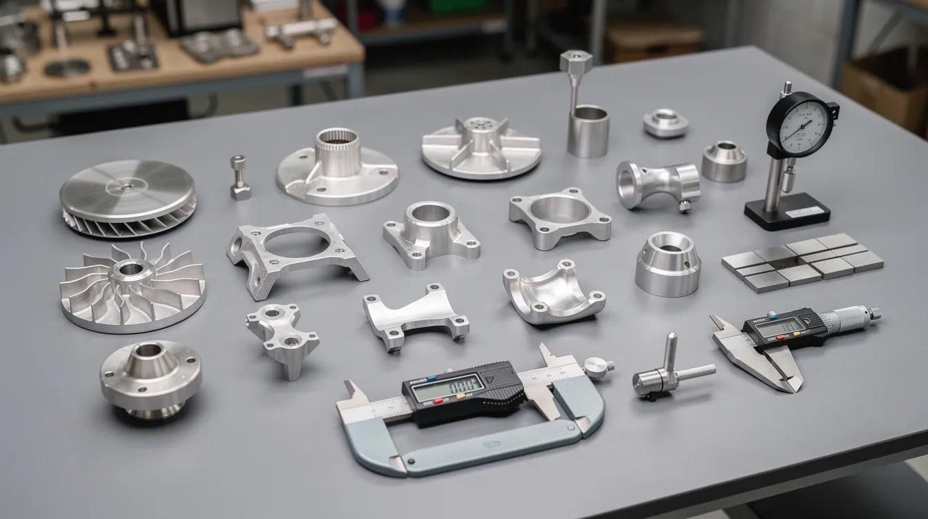
Accuracy, Tolerances, and Quality Assurance
CNC machining supports tight tolerances and consistent part quality, but “CNC precise” still requires verification through systematic quality control.
Typical tolerance ranges in precision manufacturing:
|
Tolerance Level |
Range |
Application |
|---|---|---|
|
Standard (ISO 2768-m) |
±0.1 to ±0.2 mm |
General features, non-critical dimensions |
|
Fine (ISO 2768-f) |
±0.05 to ±0.1 mm |
Mating surfaces, functional fits |
|
High precision |
±0.005 to ±0.02 mm |
Critical bores, shafts, datum features |
|
Ultra precision |
±0.001 to ±0.002 mm |
Medical implants, optical components |
CNC machining supports tight tolerances of ±0.002 mm on optimized features where machine capability, material behavior, tool condition, and workholding all align.
Inspection methods that verify these tolerances include:
-
Calipers, micrometers, and height gauges for basic dimensions.
-
Optical comparators for profile verification.
-
CMMs (Coordinate Measuring Machines) for complex 3D profiles, GD&T evaluation, and full dimensional reports.
-
Surface profilometers for roughness measurement (Ra values).
Anebon’s ISO 9001:2015 quality system includes first-article inspection (FAI), in-process checks, Statistical Process Control (SPC), and full inspection reports. Material traceability through mill certificates and batch records supports high tolerance CNC manufacturing certified for quality, which is essential for regulated aerospace and medical devices applications.
Cost Drivers in CNC Machining and How to Optimize Them
Understanding what drives CNC machining costs lets engineers make design decisions that balance performance and price before requesting a quote.
Primary cost factors:
-
Material: High-strength alloys (titanium, Inconel) cost more per kilogram and wear tooling faster than aluminum or brass.
-
Part complexity: Undercuts, thin walls, deep pockets, and features requiring multiple setups increase cycle time.
-
Tolerance tightness: Each tighter tolerance class demands additional finishing passes, slower feeds, stricter tool condition monitoring, and more rigorous inspection.
-
Surface finish requirements: A mirror finish (Ra <0.4 μm) adds grinding or polishing steps. Anodizing or plating adds post-processing cost.
-
Machining time: Directly driven by material removal volume, number of operations, and cutting parameters.
-
Setup time: Fixture design, tool loading, and alignment-amortized over batch size.
Practical DFM tips to reduce cost:
-
Relax non-critical tolerances to ISO 2768-m; reserve ±0.01 mm or tighter only for functional features.
-
Use internal corner radii ≥ 1 mm to allow standard end mills and reduce cycle time.
-
Standardize hole sizes and thread specifications to minimize tool changes.
-
Limit the number of setups by designing features accessible from fewer orientations.
-
Increase batch size when possible-setup costs are amortized across more parts.
The fastest way to cut CNC machining costs is not negotiating price-it is optimizing the design before the first chip flies.
Why Work with Anebon Metal Products Limited for CNC Machining
Founded in 2010 in Dongguan, Guangdong, China, Anebon Metal Products Limited delivers precision CNC machining, die casting, and sheet metal fabrication to overseas OEM clients who demand high accuracy and reliable quality.
What sets Anebon apart:
-
Advanced equipment: 3-axis through 5-axis CNC machines, CNC lathes with live tooling, and Swiss machining capability for small-diameter high-precision work.
-
Engineering support: Experienced engineers provide DFM feedback on every project, helping clients optimize designs before CNC programming begins.
-
Tolerance capability: Dimensional accuracy down to ±0.002 mm on critical features, with surface finishes from Ra 1.6 μm to Ra 0.05 μm.
-
Certifications: ISO 9001:2015 and ISO 14001:2015, with documented quality control processes including FAI, SPC, and full inspection reports.
-
Material versatility: Aluminum, stainless steel, titanium, brass, copper, engineering plastics, and composites.
-
Industry experience: Aerospace, medical devices, automotive, electronics, and robotics-with the inspection documentation and traceability these sectors require.
AI and robotic automation are trending advancements in CNC machining, and Anebon continues to invest in digital manufacturing technologies to deliver faster turnaround, better consistency, and competitive pricing.
Anebon is a technical partner, not just a supplier. Whether you need a single rapid prototype or full-scale OEM production, the team is ready to review your CAD file and provide actionable DFM feedback.
Ready to get started? Choose the right machined parts manufacturer for your project and request a quote from Anebon today. Share your STEP files, drawings, and specifications-the engineering team will respond with a detailed review and competitive pricing.