Top Tools for Rapid Prototyping to Accelerate Your Design Process
Tools for Rapid Prototyping in Precision Manufacturing
Rapid prototyping in precision manufacturing is not about wireframes or clickable mockups. It is about turning a CAD model into a physical, testable metal or plastic part that your team can hold, measure, assemble, and break-before committing to expensive production tooling. For product teams working in aerospace, medical devices, automotive, electronics, robotics, and industrial machinery, the tools for rapid prototyping have expanded dramatically over the past decade.
In 2015, most hardware prototyping meant basic FDM 3D prints and simple 3-axis CNC milling. By 2020, metal additive manufacturing and integrated simulation tools entered mainstream use. Today, in 2026, product designers and engineers combine AI-driven generative design, multi-axis CNC machining, rapid die casting, and sheet metal fabrication into a single development process that compresses timelines from months to a few weeks.
Prototypes help refine ideas and inform design decisions at every stage of the product development process. Rapid prototyping speeds up product development cycles significantly, reduces costs by identifying design flaws early, and enhances collaboration among team members. Rapid prototyping tools allow quick creation of interactive concepts that product managers and stakeholders can evaluate before locking in geometry, materials, or tooling.
Key benefits of modern rapid prototyping tools:
-
Shorter design cycles-iterations measured in days, not months
-
Lower risk of costly tooling failures or late-stage redesigns
-
Ability to explore ideas and test multiple variants before production
-
Improved communication between engineering, procurement, and manufacturing teams
Anebon Metal Products Limited, founded in 2010 and based in Dongguan, China, is an ISO 9001:2015 and ISO 14001:2015 certified precision manufacturer. Anebon takes designs from rapid prototypes through to full production, offering CNC machining, die casting, and sheet metal fabrication with tolerances as tight as ±0.002 mm on critical features.
From Concept to Prototype: Where Rapid Prototyping Tools Fit in the Design Process
Hardware product development typically follows a sequence: Concept → Proof-of-Concept (PoC) → Engineering Validation Testing (EVT) → Design Validation Testing (DVT) → Production Validation Testing (PVT) → Ramp to Mass Production. Prototyping tools vary in fidelity between low-fidelity concepts and high-fidelity models, and the right tool shifts at each stage.
-
Concept / PoC: Early sketches become quick prototypes using FDM 3D prints, foam mockups, or basic SLA parts. Proof-of-concept prototypes validate ideas and assumptions about form, proportion, and basic ergonomics. Tolerances are loose; surface finish is not critical. Looks-like prototypes represent the final product at an abstract level-useful for stakeholder feedback.
-
EVT / DVT: Functional parts made in production-intent materials. Works-like prototypes include core technologies and functions for testing. CNC-machined aluminum enclosures with final wall thickness, true tolerances, and realistic mechanical properties replace early prints. High-fidelity prototypes can involve sensors and conditional logic-for instance, a medical device housing with implant mating surfaces held to ±0.013 mm.
-
PVT / Pilot: Engineering prototypes are designed for manufacturing and user testing using bridge tooling, small die-casting molds, or short-run sheet metal. Surface finishes approach production intent; cosmetics and regulatory testing begin.
DFM feedback is pivotal at every stage. Anebon provides design-for-manufacturability consulting-reviewing wall thickness, draft angles, bend radii, and tolerance stack-ups-so teams can create high fidelity prototypes that transition smoothly into production.
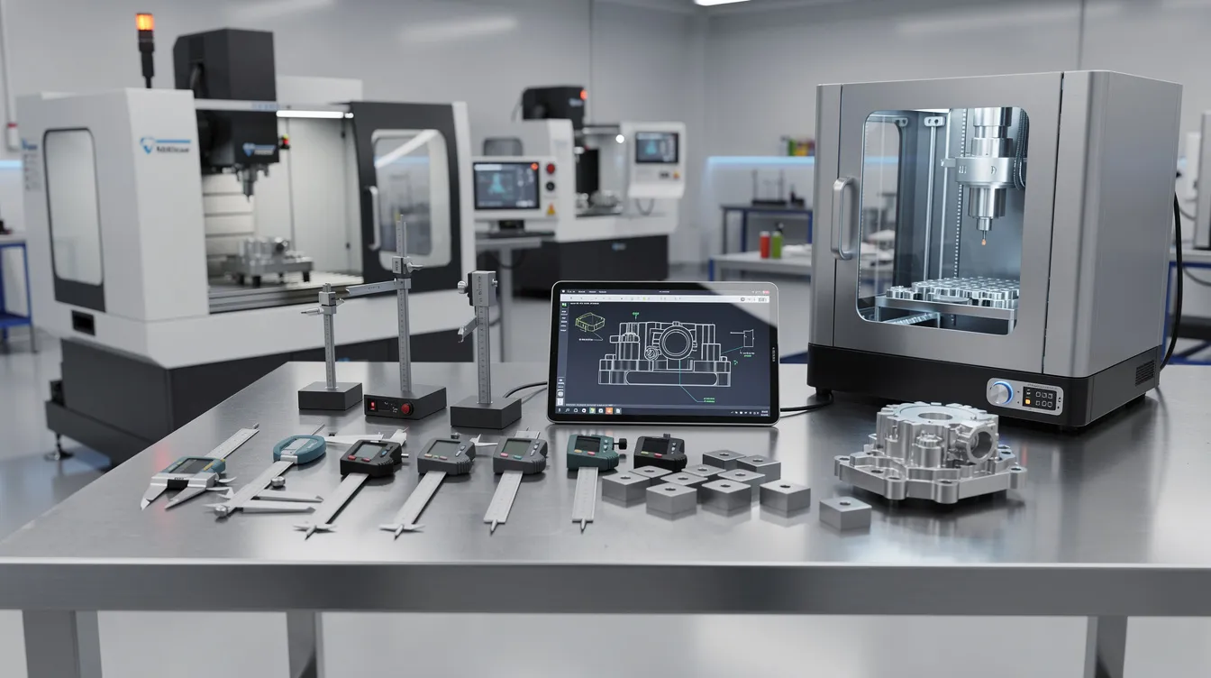
Digital Design Foundations: CAD, Simulation, and AI Prototyping Tools
Before any chips fly or powder sinters, digital tools lay the groundwork. 3D modeling and simulations are standard in industrial processes, allowing designers to catch problems before committing material and machine time.
Parametric CAD models enable rapid variant generation-change a wall thickness, rib pattern, or hole layout and replay all dependent features in minutes, allowing designers to evaluate multiple variants in parallel.
Key CAD platforms for hardware prototyping:
-
SolidWorks – Widely adopted in medical devices and consumer products; strong parametric assemblies
-
Autodesk Fusion 360 – Popular among startups; integrates CAD, CAM, and simulation including generative design modules powered by cloud compute
-
Siemens NX / PTC Creo – Standard in aerospace and automotive OEMs for complex surfacing and large assemblies; more advanced tools with a steep learning curve
Simulation and CAE tools:
-
FEA for stress and fatigue analysis
-
CFD for thermal management and airflow in electronics enclosures
-
Mold-flow and die-casting fill simulations to predict defects before cutting steel
AI prototyping tools for hardware:
-
AI-driven generative design in Fusion 360 explores hundreds of geometry alternatives based on load, weight, and material constraints
-
Topology optimization in SolidWorks reduces mass while meeting strength targets
-
AI-powered shape recognition in CAM software suggests optimized toolpaths, cutting cycle time
It is worth clarifying the difference between engineering-focused ai tools and UI/UX-oriented ai prototyping tools. Platforms like Figma with AI features, Magic Patterns, and similar web app builders serve ux designers creating individual screens and interactive components for dashboards or control panels on physical devices. Engineering AI models, by contrast, optimize geometry, predict tolerances, and simulate manufacturing loads. Anebon regularly receives CAD files created in both traditional and AI-assisted environments.
Core Physical Rapid Prototyping Methods and Machines
In 2026, most prototyping tools in hardware manufacturing combine additive manufacturing with subtractive methods and forming processes. The fastest prototyping tools are rarely a single machine-they are a workflow that matches the right process to the design stage.
The main categories covered below:
-
CNC machining – milling and turning for high fidelity metal and plastic prototypes
-
3D printing – FDM, SLA, SLS, and metal additive for concept through functional parts
-
Sheet metal fabrication – laser cutting, bending, welding for enclosures and structural parts
-
Rapid die casting – soft and bridge tooling for near-production metal parts
Anebon’s core strengths lie in precision CNC machining (including 5-axis), die casting, and sheet metal fabrication, often used after initial 3D prints to build prototypes at production-grade fidelity.
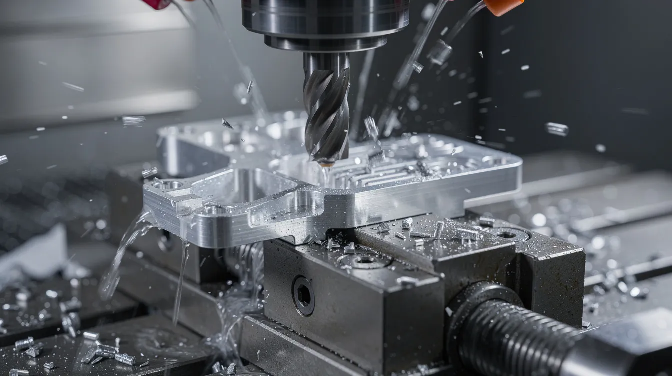
CNC Machining: High-Fidelity Metal and Plastic Prototypes
CNC milling and CNC turning are subtractive prototyping tools ideal for creating prototypes with tight tolerances and true-to-production mechanical properties.
-
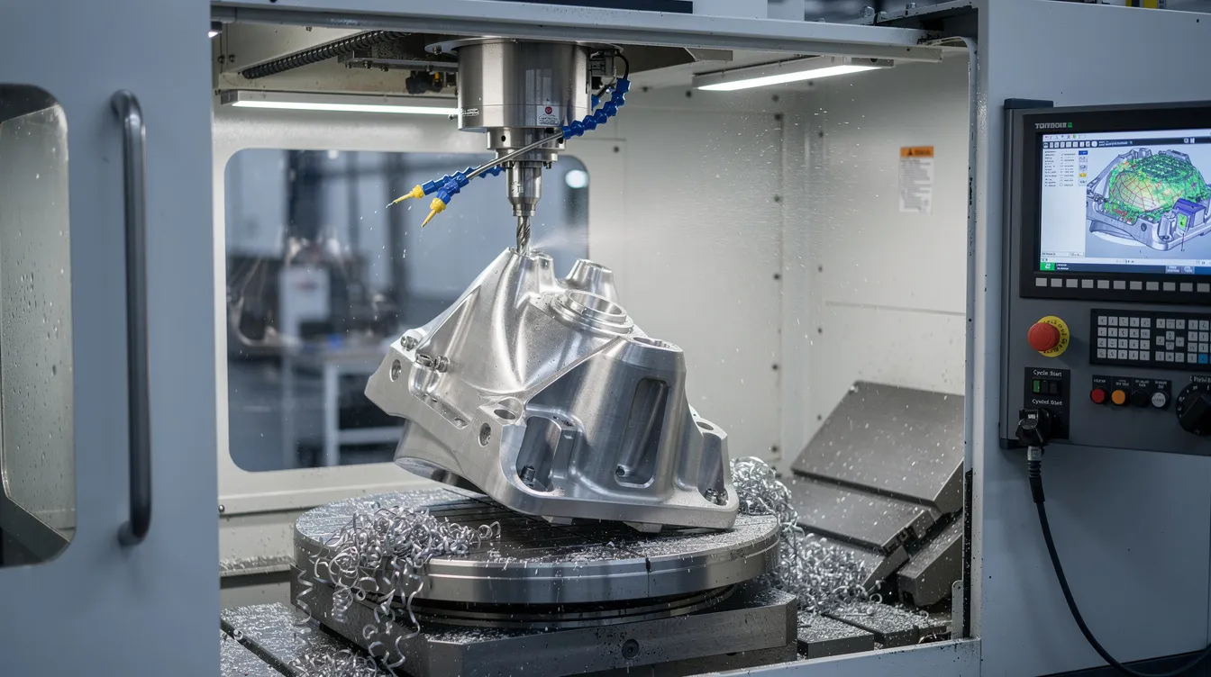
3-axis milling handles most flat and prismatic parts. 4-axis adds rotary indexing for features on multiple faces. 5-axis machining is critical for complex geometries-undercuts, curved aerospace surfaces, multi-face robotics housings-all machined in a single setup, reducing fixture changes and error accumulation.
-
Common materials: aluminum alloys (6061-T6 for general use, 7075-T6 for high-strength aerospace), stainless steels (304, 316L for medical and food-contact), titanium (Ti-6Al-4V for implants and lightweight structural parts), and engineering plastics like PEEK (heat resistant and biocompatible), POM, PC, and ABS.
-
Tolerances: aerospace prototyping demands ±0.005 mm to ±0.013 mm on critical features. Medical implant mating surfaces may require ±0.013 mm. General metal prototypes typically hold ±0.05 mm.
-
Surface finish: as-machined Ra 3.2 µm; fine machined Ra 1.6 µm; sealing surfaces Ra 0.8 µm or better.
CAM software with AI-assisted toolpath optimization reduces air-cutting and improves feed rates, supporting faster iteration. These are among the fastest prototyping tools for functional metal parts, with simple aluminum prototypes completed in 1–3 days.
Additive Manufacturing: 3D Printing Technologies for Early and High-Fidelity Prototypes
3D printers enable rapid prototyping with unmatched turnaround time for early-stage parts. 3D printing allows for quick testing of multiple design iterations, and it enables faster validation of product concepts with stakeholders.
-
FDM (Fused Deposition Modeling): FDM is the most widely used 3D printing method for prototyping. It is cost-effective for concept models, jigs, and fixtures. Limitations include visible layer lines, lower dimensional accuracy (typically ±0.2–0.5 mm), and limited material strength compared with CNC parts.
-
SLA (Stereolithography): SLA 3D printing offers the highest resolution and precision among polymer methods, with feature sizes below 0.1 mm and smooth surfaces. It is commonly used for looks-like models in medical, consumer electronics, and automotive interiors.
-
SLS (Selective Laser Sintering): SLS 3D printing is ideal for complex geometries and functional parts-lattice structures, internal ducts, aerospace brackets-without support structures.
-
Metal 3D printing (DMLS/SLM): Produces complex, lightweight metal components. Near-net shapes are printed and then finish-machined on CNC for critical surfaces. Newer systems are becoming more accessible; a workbench-sized laser powder bed fusion system priced at ~US$9,600 was announced in 2026 supporting stainless steels, tool steels, and nickel alloys.
While Anebon focuses on CNC, die casting, and sheet metal, many customers use in-house 3D printing for PoC prototypes and then send designs to Anebon for high fidelity machining and finishing.
Sheet Metal Prototyping: Enclosures, Brackets, and Chassis
Laser cutting, CNC punching, press-brake bending, and welding combine to create rapid sheet metal prototypes for electronics housings, server chassis, EV battery trays, and industrial brackets.
-
Typical materials: aluminum 5052 and 6061, cold rolled steel, stainless steel 304/316, in thicknesses from 0.5 mm up to several millimeters.
-
Tolerances: ±0.1–0.2 mm for laser-cut and bent features, depending on thickness and bend count.
-
Design systems for sheet metal (standard bend radii, hole sizes, fastener patterns) speed up design and ensure manufacturability. Using established design systems avoids custom tooling delays.
-
Lead times: single-part prototypes in 2–7 days; complexity (deep draws, tight radii, multiple bends) adds time.
Anebon’s digital tooling-CNC programs and bending libraries-enables the team to move from CAD to first articles in days for small batches, supporting different projects with rapid turnaround.
Rapid Die Casting and Bridge Tooling
Rapid die casting produces higher volumes of metal prototypes using aluminum, zinc, or magnesium alloys. It is the right tool when teams need to validate thermal performance, structural integrity, and cosmetic finish for automotive housings, electronics enclosures, or industrial components.
-
Rapid tooling (aluminum or pre-hardened P20 steel): US$1,500–$8,000, lead time 2–4 weeks offshore, supports 500–10,000 shots
-
Bridge tooling (pre-hardened steel): US$8,000–$28,000, lead time 6–10 weeks, supports 10,000–100,000 shots
-
Full production tooling: 14–20 weeks, 1,000,000+ shot life
Anebon offers die casting plus CNC post-machining and surface treatments to deliver near-production, high fidelity prototypes with customization options including different alloys, surface finishes, and tight critical-feature tolerances. Bridge tooling connects prototyping to mass production, letting teams fine tune cosmetics and performance before the final product hits the line.
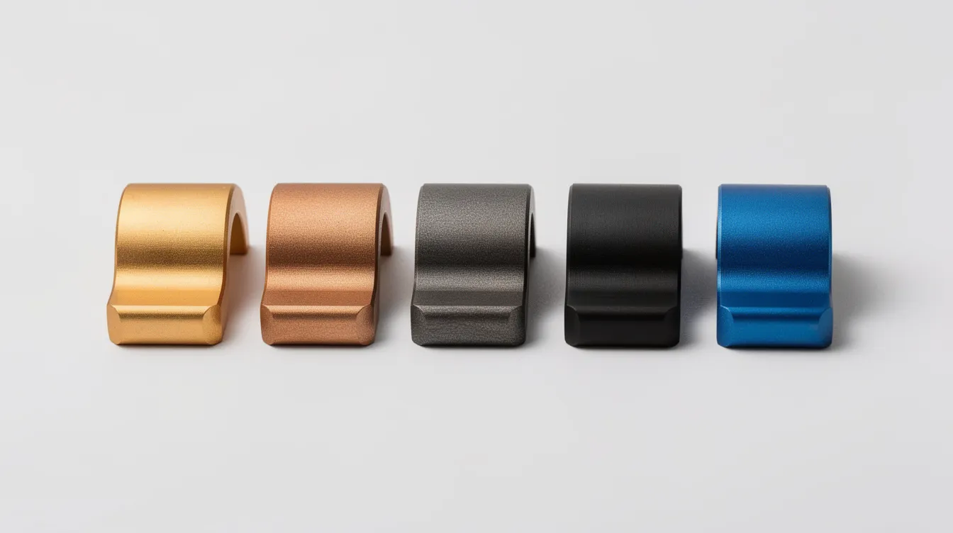
Surface Finishing and High-Fidelity Prototype Appearance
Surface treatments are critical tools for converting functional prototypes into high fidelity prototypes that accurately represent final products. A prototype with the right finish creates realistic experiences for trade shows, investor demos, and regulatory submissions.
Key finishing methods:
|
Finish |
Typical Ra (µm) |
Common Use |
|---|---|---|
|
As-machined |
~3.2 |
Non-cosmetic internal parts |
|
Bead blasting |
~1.6–2.0 |
Uniform matte texture, electronics housings |
|
Brushing |
~1.0–1.6 |
Consumer product panels |
|
~0.8–1.6 |
Color, corrosion protection, aerospace/medical |
|
|
Hard anodizing (Type III) |
~0.8 |
Wear-resistant surfaces |
|
Powder coating |
varies |
Durable color finish, automotive brackets |
|
Electroless nickel |
~0.4–0.8 |
Corrosion and wear, electronics |
|
Mirror polish |
~0.1–0.2 |
Optical, premium cosmetic parts |
Cosmetic prototypes for different platforms-trade shows, functional testing, client demos-may combine tight tolerances with custom colors and textures to match brand design standards. Anebon can apply multiple finishes on a single prototype run, letting teams evaluate multiple variants of color, texture, or coating side-by-side.
AI-Powered and Digital Collaboration Tools in Hardware Prototyping
While ai prototyping tools are often associated with the ux design process-creating interactive prototypes for apps and web interfaces-similar ai tools and digital platforms now accelerate mechanical and manufacturing prototyping.
AI tools in engineering prototyping:
-
AI-assisted generative design for weight reduction and structural optimization, exploring unlimited projects of geometry combinations in milliseconds
-
Automated tolerance analysis that flags stack-up issues before machining
-
AI-powered quoting systems that predict lead times and cost based on part geometry, material, and quantity
UI/UX ai tools still matter for hardware teams. Physical products with embedded displays, dashboards, or control panels need interface prototypes alongside mechanical parts. Figma is a leading prototyping tool for UX/UI designers working on such interfaces. Figma AI automates interaction setup within existing designs. UX Pilot generates app interfaces from text descriptions. Google Stitch can create prototypes from text prompts or sketches. Framer AI allows users to publish websites directly from the platform-useful for landing pages tied to product launches. Relume generates sitemaps and wireframes for website design. AI-powered tools can generate ui components and frontend code without requiring coding experience, and most prototyping tools offer free plans or trials for testing. ProtoPie is known for high-fidelity capabilities without requiring coding, handling conditional interactions and complex logic for hardware-connected interfaces. Arduino and Raspberry Pi are essential for hardware interactions and sensors, letting teams build prototypes with multiple screens and conditional logic tied to physical inputs.
AI can expedite the creation of interface prototypes across individual screens, and these tools support real time collaboration between product designers, engineers, and product managers in different time zones.
Anebon supports digital collaboration through secure file transfer, version control for CAD files and drawing revisions, and structured communication workflows that improve communication with overseas OEMs on different projects. Teams working across different platforms benefit from Anebon’s ability to accept STEP, IGES, and native CAD formats.
Choosing the Best Prototyping Tools for Your Project
Choosing the right tool depends on project complexity and workflow. The ideal prototyping tool depends on project focus-whether digital or physical-and the stage of development.
Decision-making framework:
-
Material and mechanical load: If the prototype must withstand real operational stress, CNC machining in production-intent metal is the right prototyping tool. 3D printing suits early geometry validation.
-
Cosmetic expectations: Need production-representative surfaces? CNC + anodizing or powder coating. Exploring form only? SLA or FDM.
-
Tolerance requirements: ±0.01 mm or tighter → CNC. ±0.2 mm acceptable → SLS or sheet metal bending.
-
Target quantities: 1–5 pieces → CNC or 3D printing. 20–500 pieces → rapid die casting or sheet metal. 500–10,000 → bridge tooling.
Concrete scenarios:
-
A 20-piece medical implant trial requiring Ti-6Al-4V at ±0.013 mm → 5-axis CNC machining with CMM inspection
-
A 500-piece electronics enclosure pilot run → rapid die casting with aluminum tooling, delivered in a few weeks
-
Early concept validation for a robotics gripper → FDM print, then SLS for functional load testing
Iteration speed is a key consideration when choosing a prototyping tool. Versatility in prototyping tools supports a broad range of design needs. Rapid prototyping tools help validate ideas and reduce development risk by catching problems before expensive production tooling is committed. Prototyping tools help validate ideas and assumptions at every stage.
The best prototyping tools for your project are often a combination-not a single machine. The best tool is the workflow that matches your timeline, tolerance, and volume requirements.
Budget matters: most prototyping tools vary in cost from a free plan for digital design tools up to paid plans for advanced features in CAE software, and from a basic plan for simple CNC parts to a professional plan for complex multi-process assemblies. A pro plan on CAD software combined with a capable manufacturing partner covers most hardware prototyping needs. Always weigh lead-time against cost, and involve your manufacturer early. Teams working on unlimited prototypes across unlimited projects benefit from establishing a relationship with an ISO-certified partner.
Integrating Rapid Prototyping with Quality Assurance
Quality assurance is part of the prototyping toolset, not an afterthought. When teams test prototypes for regulatory submissions, safety validation, or functional performance, inspection data must be reliable and traceable.
QA tools and methods for prototypes:
-
CMM (coordinate measuring machines) for dimensional verification against GD&T callouts
-
Optical measurement and laser scanning for complex surfaces
-
Hardness testing (Rockwell, Vickers) to confirm material properties
-
Surface roughness measurement (profilometry) to verify Ra values
-
Material certifications and mill test reports for aerospace and medical traceability
Statistical process control, even on small batches, helps de-risk later mass production by establishing process capability data with real data from actual parts. Anebon’s ISO 9001:2015 and ISO 14001:2015 systems apply equally to prototypes and production runs, providing inspection reports, first article inspection (FAI), and full measurement documentation. This allows teams to perform user testing and user research with parts they can trust.
Practical Tips for Faster, More Effective Hardware Prototypes
A great idea can stall if the prototyping process is inefficient. Here is a checklist for engineers looking to move faster:
-
Simplify geometry on first iterations. Remove cosmetic fillets, engravings, and non-critical features. Add them back once form and fit are confirmed.
-
Relax non-critical tolerances. Specify tight tolerances only on functional mating surfaces and leave general dimensions at ±0.05 mm or wider.
-
Standardize fasteners and hole sizes. Using common M3, M4, and M5 thread sizes and standard drill diameters reduces tooling changes and cost.
-
Create multiple variants of critical features (snap fits, sealing surfaces, heat sinks) within a single prototype batch to test options in parallel rather than sequentially.
-
Mix fidelity levels. Start with 3D-printed quick prototypes for form, then move to CNC or sheet metal once the design stabilizes. This approach addresses user needs efficiently without over-investing early.
-
Involve manufacturing partners early. Send Anebon your CAD for a DFM review before finalizing geometry. Early feedback on tolerances, draft angles, and material selection prevents redesign cycles later in the design process.
How Anebon Supports Rapid Prototyping Through to Production
Anebon Metal Products Limited provides end-to-end rapid prototyping and manufacturing services built around precision metal fabrication.
-
Capabilities: CNC milling and turning (including 5-axis), die casting, sheet metal fabrication, and a broad materials portfolio-aluminum, titanium, stainless steel, engineering plastics
-
Surface treatments: anodizing, powder coating, electroplating, polishing, bead blasting, painting, and laser engraving with new features added as customer requirements evolve
-
Experience: since 2010, serving overseas OEMs in aerospace, medical devices, automotive, electronics, and robotics, with typical prototype volumes from 1 to 10,000 pieces
-
Engagement flow: RFQ with CAD and requirements → DFM feedback → prototype production → inspection and reporting → iteration → transition to low- and high-volume production
-
Certifications: ISO 9001:2015 (quality) and ISO 14001:2015 (environmental), applied to every project regardless of volume
Anebon supports urgent rapid prototyping timelines and aligns with global product launch schedules, allowing designers and engineers to maintain momentum through EVT, DVT, and PVT without switching suppliers.
Next Steps: Getting a Prototype Quote from Anebon
If you are ready to move from concept to physical prototypes, prepare the following for the most accurate and fastest quote:
-
3D CAD files in STEP or IGES format (native SolidWorks, Fusion 360, NX, or Creo files also accepted)
-
2D drawings with tolerances, GD&T callouts, and critical dimensions highlighted
-
Material specifications and any regulatory or industry standards that apply
-
Surface finish requirements (e.g., anodized, powder coated, Ra target)
-
Target quantities and delivery dates for each prototype iteration
-
Functional notes – mechanical loads, operating environment, temperature range, assembly context – so Anebon can recommend the right tool and process mix
Anebon typically responds to RFQs within 24–48 hours, with prototyping lead times ranging from 3 days for simple CNC parts to 4–6 weeks for rapid die casting with bridge tooling, based on recent 2024–2026 project benchmarks.
Contact Anebon Metal Products Limited to start your next rapid prototyping project – from a single proof-of-concept part to a full pilot production run.