The Ultimate Guide to Metal Bending Techniques and Applications
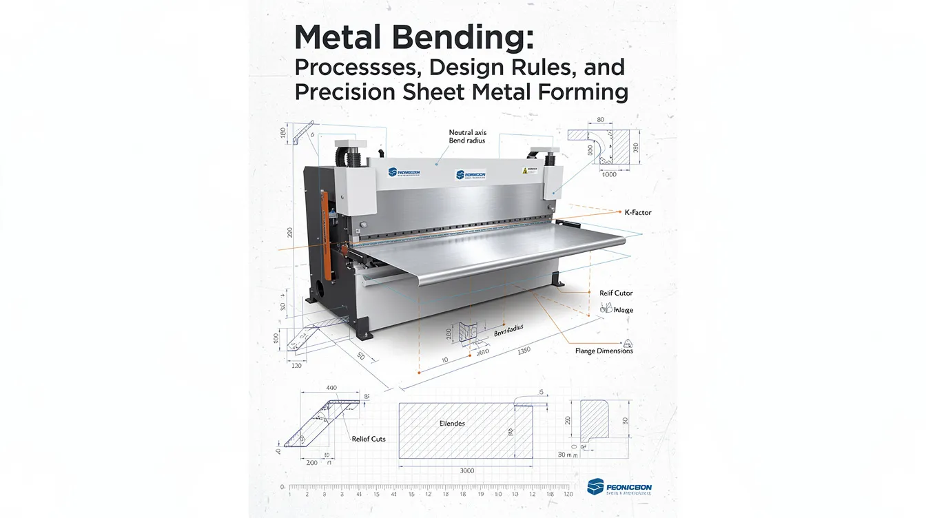
Metal Bending: Processes, Design Rules, and Precision Sheet Metal Forming
Introduction to Metal Bending in Modern Fabrication
Metal bending is a core manufacturing process that transforms flat sheets and plates into functional three-dimensional geometry through controlled permanent deformation. Unlike machining or cutting, metal bending alters shape without changing volume, meaning the material you start with is the material you end with. This makes the bending process one of the most material-efficient forming methods available. Metal bending minimizes material waste during production while enabling complex shapes from a single metal piece.
For OEM design engineers and manufacturing engineers working in automotive, aerospace, electronics, robotics, and medical devices, bending is how brackets, chassis, enclosures, structural profiles, and a metal door frame all come to life. Since the 1950s, the evolution from manual brake presses to hydraulic and CNC-controlled machines has pushed this manufacturing process into high precision territory, supporting tolerances that modern product designs demand.
This article focuses on industrial sheet metal bending for precision work, from prototype through full production. Modern bending techniques can handle various metals efficiently, making the process essential across various applications. Anebon Metal Products Limited, founded in 2010 in Dongguan, operates as an ISO 9001:2015 and ISO 14001:2015 certified precision metal fabrication partner, offering bending as part of an integrated workflow that includes CNC machining, die casting, and surface treatments.
The sections ahead cover the basic types of bending methods (air bending, bottoming, rotary bending, roll bending, and more), key design concepts like bending radius, bend allowance, and k factor, as well as practical design tips for OEM engineers looking to get parts right on the first run.
Fundamentals: How the Metal Bending Process Works
In a typical bending operation, a sheet metal blank is positioned against a backgauge, then a punch descends into a die block, forcing the material to deform around a defined bending radius. During this process, the outer fibers of the material stretch under tension while the inner fibers compress. Between these zones lies the neutral line – a theoretical plane within the sheet thickness that neither stretches nor compresses.
Key geometric terms every engineer should know include the inside radius (the distance from the inner bend surface to the bend center), the bend angle (determined by the degree of deformation applied), flange or leg length (the straight edges extending from the bend), and the neutral axis position within the material thickness. These dimensions directly influence how much material is consumed in the bend and how the flat pattern should be developed.
The bending process works by loading the material beyond its yield strength to achieve permanent deformation. When the load is removed, elastic recovery causes the part to spring back slightly toward its original position, changing the final angle and slightly opening the radius. Material thickness affects bend allowance and springback significantly – thicker sheets and higher-strength alloys exhibit greater springback. Key factors influencing metal bending include material thickness, type, and grain direction.
Standard sheet thickness for press brake forming ranges from about 0.5 mm to 6 mm. Above roughly 10–12 mm, the work enters plate bending territory, requiring different equipment and substantially higher tonnage. Press brakes are commonly used for metal bending operations across this full range. Modern CNC press brakes with programmable backgauges achieve position control within approximately 0.01 mm and angle control within about ±0.5°, ensuring bending processes deliver high precision and repeatability. Bending also enhances the strength and rigidity of metal components by creating structural stiffness through geometry rather than added material.
Common Bending Methods in Sheet Metal Fabrication
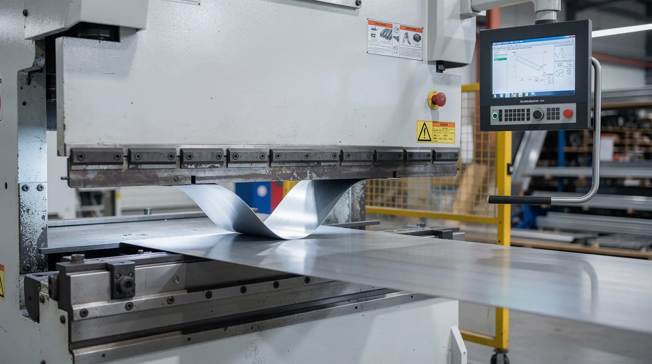
Different metal bending techniques trade off speed, tool cost, achievable angle accuracy, surface finish quality, and required tonnage. Metal bending methods differ based on the way force is applied, the shapes produced, and the precision achievable. Choosing a metal bending method depends on factors such as material type, thickness, and required accuracy.
The core industrial methods include v bending, U bending, air bending, bottoming, coining, rotary bending, wipe (edge) bending, roll bending, step (bump) bending, and folding. Common metal bending techniques include air bending, bottoming, and coining as the three primary press brake approaches. V-bending accounts for around 90% of all bending jobs globally, making it the dominant form for brackets, chassis, and enclosures.
Hot metal bending requires heating metals to a pliable state and is reserved for thicker sections or difficult alloys like titanium. Stretch forming is another specialized bending method for aerospace skins and complex curves. However, the majority of sheet metal work relies on cold press brake forming. Metal bending methods vary in efficiency, precision, and application, and Anebon selects the appropriate method based on required tolerance, material (aluminum, stainless, carbon steel, titanium), and production volume.
V Bending, U Bending, and Step (Bump) Bending
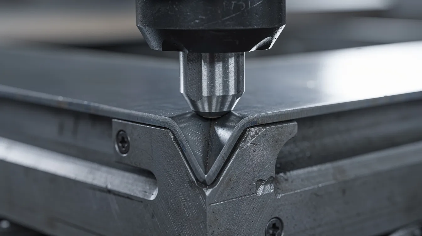
V bending and its variants cover the vast majority of sheet metal bending jobs. In a standard v bending setup, a punch presses the workpiece into a v die, with the v opening width typically set at 6–10 times the material thickness for air bending. A narrower v opening produces a tighter inside radius but requires more force, while a wider opening gives a larger radius with less force. The v shape of the die and the tool shape of the punch together define the final bend geometry.
U bending uses a punch and a matching u shape die to form channel shapes in a single stroke. This die bending method is common for structural channels, enclosures, and brackets where the inside profile must closely conform to a u shape. The bottom tool captures the material on both sides, producing consistent flanges.
Step (bump) bending approximates a large radius or cone by executing a sequence of small V bends along the workpiece. Each incremental bend adds a facet; more steps produce a smoother approximated curve. This technique is widely used for hoppers, guards, and architectural panels. For guidance on forming conical shapes, see How To Make A Cone From Sheet Metal. Punched shapes determine the final profile and bend radius in metal bending, and Anebon uses CNC backgauge programming to automate step bending for consistent spacing across large-radius features.
Press Brake Bending Types: Air Bending, Bottoming, and Coining
These three terms describe how far the punch drives sheet metal into the die and how the material contacts the bending tools during press brake forming.
Air bending is the most widely used bending method on modern CNC press brakes. The sheet contacts only the punch tip and the die edges, with the punch stopping above the bottom die floor. Air bending is a flexible method requiring less force than other methods, and it allows various bend angles without changing the die – a single tool set can produce a wide range of bend angles simply by varying stroke depth. The tradeoff is higher springback sensitivity, with typical angular accuracy around ±0.5–1°. Air bending allows for various bend angles without changing the die, making it ideal for shops running fewer tools across diverse part geometries.
Bottoming forces the material to conform closely to the die angle, substantially reducing springback. Bottom bending offers better accuracy and repeatability than air bending, typically achieving ±0.25–0.5° angular precision. Bottoming provides better repeatability and reduced springback compared with air bending, but requires dedicated tooling matched to each material thickness and desired angle, increasing tooling cost.
Coining applies extreme pressing force to permanently imprint the punch radius into the material, virtually eliminating springback. Coining requires 5–30 times more force than air bending for precision, resulting in greater accuracy (better than ±0.25°) but significant tool wear and higher energy consumption. Press brakes are versatile machines for bending metal sheets across all three approaches. Hydraulic CNC press brakes enhance precision and efficiency in bending by enabling programmable stroke control, automatic tonnage adjustment, and stored correction tables.
Anebon primarily uses CNC-controlled air bending and bottoming, choosing coining selectively for small, high precision features where the design justifies the extra tonnage.
Other Bending Methods: Wipe, Rotary, Roll, Three-Point, and Joggle Bending
Beyond standard V bending, several techniques address specialized geometry or surface finish requirements across various metal bending techniques.
Wipe (edge) bending clamps the sheet and wipes the free edge over a form block. Wiping is typically used for creating simple 90-degree angles along the edge of a sheet. It is fast for flanges and hems but carries increased risk of surface scratching, so it is often reserved for non-cosmetic edges. Folding handles large sheets without needing deep press brake tooling and works on a similar principle.
Rotary bending uses a rotating die segment to form the bend with minimal contact, making each tool offers unique advantages for pre-painted, anodized, or brushed surfaces. This method can achieve bend angles past 90° in a single stroke and leaves less springback than standard air bending. For details on working with finished surfaces, see How To Bend Stainless Steel Sheet Metal.
Roll bending passes flat sheets through three rollers to produce smooth large-radius curves, cylinders, or cones. Roll bending uses rollers to bend metal plates into curves, cylinders, or cones, and roll bending produces smooth large-radius curves efficiently and consistently. Roll forming allows for extremely fast continuous production after initial tooling investment. For circular forms, How To Bend Sheet Metal Into A Circle provides additional guidance.
Three-point bending uses an adjustable bottom tool with movable supports, allowing precise radius and angle control for long profiles or thick material where standard dies are impractical.
Joggle bending produces an offset (S-shaped) bend in one operation, commonly used in aerospace lap joints where two panels overlap with a small offset, typically less than about 5× thickness. For a deeper look, see Understanding The Joggle: Essential Techniques For Sheet Metalworking. Tube bending maintains tube shape while minimizing wrinkles and flattening, serving as yet another specialized forming process. Anebon can combine these various methods with CNC positioning and in-process inspection for critical assemblies.
Key Design Concepts: Bend Radius, Bend Allowance, Bend Deduction, and K-Factor
Accurate flat-pattern development is essential for ensuring formed parts match design intent, especially when folding multiple bends in different directions from flat sheets.
Inside bend radius is the most critical dimension. The minimum bend radius should generally be equal to or greater than the sheet thickness – this is a widely used rule of thumb for most steels. The inside bend radius should generally be equal to or greater than the thickness of the sheet metal to avoid cracking or excessive thinning at the outer surface. Material properties determine the required force and potential for cracking during bending, so certain metals and harder tempers require larger radii. For detailed radius guidelines, see How To Bend Sheet Metal With A Radius.
K-factor defines where the neutral line sits within the material. The k factor formula expresses this as the distance from the inside surface to the neutral axis, divided by material thickness. Typical k factor values range from 0.3 to 0.5 – lower for tight radii or high-strength material, higher for softer or loosely bent material.
Bend allowance (BA) is the arc length of the neutral axis through the bend region, calculated as:
BA = (π / 180) × θ × (R_i + K × T)
For a 90° bend in 2 mm mild steel with an inside radius of 2 mm and K = 0.40, BA ≈ 1.5708 × (2 + 0.8) = 4.43 mm. If K were incorrectly assumed at 0.50, BA would shift by about 0.31 mm – enough to cause fit problems in a multi-bend part.
Bend deduction (BD) is the amount subtracted from the sum of outside flange dimensions to determine the flat blank length. CAD sheet metal modules typically ask for either BA or BD. Anebon’s engineering team helps overseas OEMs optimize bend radii, k factor values, and flat-pattern calculations for their specific material lots and tooling.
Materials and Thicknesses: What Bends Well (and What Doesn’t)
Ductility and yield strength are the primary drivers of how easily you can bend metal. Highly malleable materials handle tight radii and show less springback, while high-strength alloys demand more force and larger radii.
Aluminum is lightweight and highly malleable, making it popular for electronics housings, automotive parts, and aerospace brackets. Alloy 5052-H32 bends well with low work-hardening, while 6061-T6 is stronger but cracks more easily at tight radii. Bending parallel to the grain increases the risk of cracking, while perpendicular bending is stronger – always orient bends transverse to the rolling direction when possible.
Mild steel is favored for its excellent formability and strength. Cold-rolled sheet in the 0.5–6 mm range bends predictably with moderate springback (typically 0.5–2°) and a minimum inside radius of approximately 1× sheet thickness.
Stainless steel is known for its corrosion resistance but presents challenges in bending. Austenitic grades like 304 and 316 work-harden rapidly, producing springback of 2–5° and requiring bending radii of 1.5–2× thickness or more.
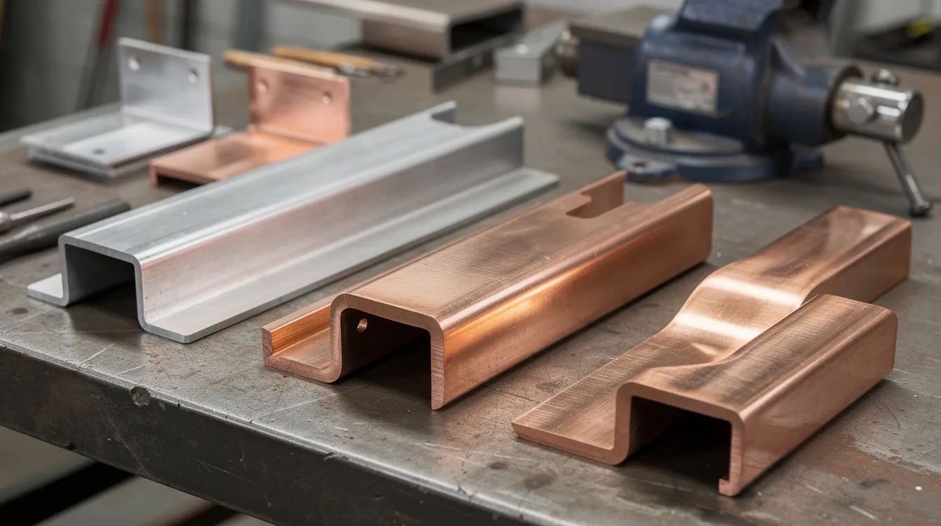
Copper is highly malleable and conductive, handling very tight radii with minimal springback. Brass has low friction properties, suitable for fittings, and bends cleanly but requires non-marring tools for cosmetic work. These other metals require attention to surface protection during the bending operation.
For harder or exotic materials like titanium and high-strength steels, larger inside bend radii and sometimes warm forming are necessary. Increasing sheet thickness raises required tonnage, impacts achievable minimum radius, and may shift the method choice from coining to air bending or roll bending.
Bending Tools, Press Brakes, and Supporting Equipment
The modern CNC press brake is the central machine for precision sheet metal bending. Key specifications include maximum tonnage, bend length, and CNC axes controlling backgauge position and crowning. Press brakes are versatile machines for metal bending, and universal metal bending machines perform multiple bending tasks efficiently across different part geometries.
Punch and die selection drives the outcome. Standard V dies come in various v opening widths matched to sheet thickness. Gooseneck punches provide clearance around previously formed flanges. Radius tools create specific inside radii, while acute-angle dies handle bends tighter than 90°. Each tool offers unique advantages depending on the geometry required. For a comprehensive overview of tooling options, see Which Tool Is Used To Bend Sheet Metal.
Auxiliary equipment includes hemming tools, joggle tools, offset dies, and rotary inserts. Backgauges with multiple axes position blanks precisely, while laser angle sensors provide real-time measurement during the pressing cycle. For pre-finished or cosmetic parts, non-marring polymer or urethane die inserts prevent scratching.
Tool setup is critical: selecting the correct die opening, punch radius, and backgauge position for each bend determines whether a part comes out right. Anebon operates CNC press brakes with multi-meter bending lengths and sufficient tonnage for thicker stainless steel, with experienced operators ensuring repeatability for overseas OEM supply.
Managing Springback, Accuracy, and Tolerances
Springback is elastic recovery that changes the final bend angle after unloading. In practice, mild steel springs back 0.5–2°, stainless steels 2–5°, and harder aluminum alloys 3–5°. Without compensation, no part hits its target angle.
Account for springback by over-bending slightly to achieve the desired angle – this is the most common strategy. Other methods include selecting tighter punch radii, using bottoming for less springback, or applying coining for demanding tolerances. CNC press brakes store material- and tool-specific correction tables, allowing automatic angle adjustments as the machine accumulates feedback from operator input and inspection results. Simpler methods of compensation involve manual trial bends, but CNC approaches deliver greater accuracy over long runs.
Realistic tolerance ranges for OEM parts sit around ±0.5° angular and ±0.25 mm flange length for most applications. Tighter specifications drive cost through additional tool setup time, extra inspection, or switching to coining. In-process quality control uses first-article inspection, angle gauges, CMM or 3D scanning for complex shapes, and statistical sampling for high-volume runs.
Anebon’s ISO 9001:2015 system ensures traceable inspection plans and documented bend parameters, helping overseas customers maintain consistent quality with a similar bend outcome across batches and years.
Design for Manufacturability (DFM) in Sheet Metal Bending
Good DFM saves time, material, and rework. Here are the guidelines manufacturing engineers and designers should follow:
-
Minimum flange length: At least 3× material thickness or more, to prevent the flange from dropping into the die during the bending operation.
-
Hole and slot placement: Holes and slots should be kept at least 2.5 times the material thickness away from the bend area to avoid distortion, especially for threaded or tight-tolerance features.
-
Grain direction: Bend perpendicular to the rolling direction. Bending parallel to the grain increases cracking risk – this applies especially to aluminum and high-strength steels.
-
Adjacent bends: Leave clearance between sequential bends to avoid tool interference when forming boxes or channel shapes. Optimizing the bend sequence can save time and money in bending processes. For sequence planning guidance, see Sheet Metal Forming Sequence: Optimizing Bend Order For Complex Geometries.
-
Bend reliefs: Add small corner reliefs (minimum width ≥ material thickness) to prevent tearing at intersections and allow flanges to form cleanly.
-
Symmetry and orientation: Nearly symmetric parts are easy to bend backwards on the shop floor. Use clear drawing views, markings, or asymmetric features to reduce errors.
Anebon routinely provides DFM feedback during the RFQ stage, suggesting changes to bend radii, flange dimensions, or hole positions before tooling and production begin.
Integrating Bending with CNC Machining, Laser Cutting, and Assembly
Sheet metal bending is rarely a standalone operation. It follows cutting (laser, punch presses, waterjet) and may precede welding, riveting, or CNC machining of critical faces. Metal bending allows for complex shapes from a single metal piece, reducing assembly steps compared to other methods that rely on welding multiple components.
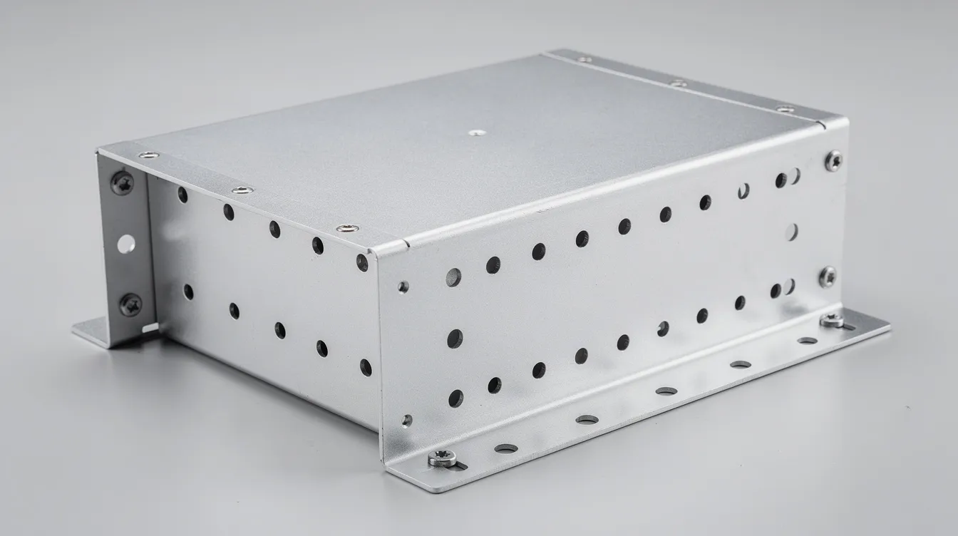
A typical Anebon workflow for an OEM enclosure starts with CNC laser cutting of flat blanks, adding countersinks or local machining features, then precision bending, followed by spot welding or riveting, and finally surface treatments like powder coating or anodizing. Tight-tolerance interfaces – mounting faces for bearings, motor housings, or a hydraulic press frame – may be CNC machined after bending to ensure final positional accuracy.
Consistent bend angles and flange lengths are essential to maintain hole alignment across multi-part assemblies. CAD and CAM integration, including importing STEP files and using sheet metal modules, helps automatically generate flat patterns with correct bend allowance values. There is no seismic sense in guessing flat patterns manually when software and experienced fabricators can verify them before cutting begins.
When to Partner with Anebon for Precision Metal Bending
Outsourcing to an experienced, ISO-certified manufacturer makes sense when your parts involve complex multi-bend geometry, tight tolerances across several techniques, mixed processes (bending plus CNC machining and die casting), or medium-to-high production volumes. Anebon offers precision sheet metal fabrication alongside CNC machining (including 5-axis milling and turning), die casting, a wide materials range, and comprehensive surface treatments.
For overseas OEMs and R&D teams, Anebon supports rapid prototyping through full production, providing DFM consulting on bend radius selection, k factor optimization, and flat-pattern development. The company’s own advantages include integrated quality systems, experienced operators, and the ability to handle everything from a simple bracket in mild steel to a multi-bend titanium aerospace component. As a main article takeaway: getting the bending right at the design stage prevents costly rework downstream.
Prepare your 3D models (STEP format preferred) and technical drawings with bend notes, and Anebon can provide quotations covering forming, finishing, and QC. Explore Custom Precision Sheet Metal Bending Parts to see representative capabilities, or reach out directly to request a quote and discuss DFM with the engineering team.