The Best Ways to Bend Metal Sheet: Tools and Techniques Explained
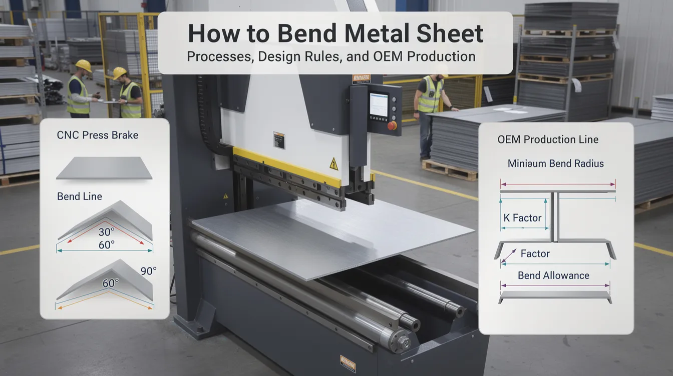
How to Bend Metal Sheet: Processes, Design Rules, and OEM Production
Introduction to Bending Sheet Metal
When you need to transform a flat piece of sheet metal into a functional bracket, enclosure, or structural component, bending is the go-to forming process. Bending sheet metal involves applying force to deform a flat sheet into a specific shape along a straight axis, creating angled flanges or complex profiles from a single piece of material. For OEM parts across automotive, robotics, electronics, and industrial machinery, this process delivers results that welding and riveting simply cannot match.
Sheet metal bending is faster than welding and riveting, and it produces structurally stronger parts because there are no drilled fastener holes or heat-affected zones weakening the material. Modern fabrication shops work with sheet thicknesses between 0.5 mm and 6 mm across carbon steel, stainless steel, and aluminum alloys. Bending is cost-effective for low- to medium-volume production runs, making it the preferred method for OEM programs that need precision without hard tooling investments.
Anebon Metal Products Limited is an ISO 9001:2015 and ISO 14001:2015 certified precision fabrication partner based in Dongguan, China. With capabilities spanning rapid prototyping through full production, Anebon provides DFM consultation, tight tolerances, and complete sheet metal fabrication services for overseas OEM clients.
Key takeaways about sheet metal bending:
-
Typical material thickness range for precision OEM bending: 0.5–6 mm
-
Common materials: mild steel, stainless steel (304/316), aluminum alloys (5052/6061), copper, brass
-
Bending can produce parts from a single piece of material, eliminating assembly steps
-
Preferred over welding for cleaner joints, tighter dimensional control, and reduced post-processing
Basic Concepts: How We Bend Sheet Metal
To bend sheet metal effectively, you need to understand a handful of core terms. Deformation occurs by compressing the inside of the bend while stretching the outside, and the material’s yield strength must be exceeded for permanent plastic deformation during bending.
-
Bend line – the straight line across the sheet where bending occurs
-
Bend angle – the included angle between the two flanges after forming
-
Flange – the flat portion of the sheet on either side of the bend
-
Inside radius – the radius of the inner surface of the bend; critical for preventing cracks
-
Bent edge – the formed edge along the bend zone where material transitions from one flange to the other
-
Neutral axis – an internal plane that experiences neither tension nor compression; its position shifts depending on material, radius, and bending method
The typical bending process flow in OEM fabrication runs as follows:
-
Raw sheet → laser cutter or CNC punching to cut the flat blank and features
-
Deburring edges from cutting
-
Bending on a press brake or folding machine
-
Secondary operations: tapping, PEM hardware insertion, welding
-
Surface finishing: powder coat, anodize, plating, or painting
The difference between DIY bending with a vise and hand seamers versus industrial CNC press brake bending is dramatic. Sheet metal bending uses press brakes and rollers for shaping at production scale, delivering repeatability and accuracy that bench tools cannot approach.
Common Industrial Methods to Bend Sheet Metal
Professional shops choose from several methods to bend metal depending on part geometry, material thickness, and volume. Bending methods need to account for material thickness and desired bend angles. Here is a quick overview:
-
Air bending – punch presses sheet into a v shaped die without contacting the bottom; most common
-
Bottoming – sheet fully seats against the bottom die for greater accuracy
-
Coining – extreme pressure eliminates springback almost entirely
-
Folding/wiping – beam swings sheet around a clamp for long straight bends
-
Roll bending – rollers form large-radius curves and cylinders
Anebon typically uses CNC press brake bending (air bending and bottoming) for most sheet metal parts, and roll bending for large radii and cylindrical profiles.
Air Bending on the Press Brake
In air bending, the punch presses the sheet into a v shaped die opening but does not drive it all the way to the bottom tool. A gap of air remains between the sheet and the die bottom, which is where the method gets its name.
Air bending is the most versatile method and requires compensation for springback. The bend angle is controlled by punch stroke depth rather than a fixed die geometry, meaning one punch and die set can produce multiple angles.
-
Requires roughly one-third to one-half the tonnage of bottoming for the same material and bend
-
Typical accuracy: ±0.3° to ±0.5° with CNC angle control on medium-thickness steel and aluminum
-
Brake presses can accommodate material thicknesses from 0.5mm to 20mm
-
Ideal for prototypes, mixed OEM batches, and parts requiring frequent angle changes
-
CNC bending can achieve accuracy levels of ±0.05 mm on critical linear dimensions
-
Fewer tool changes keep cycle times short and labor costs down
Bottoming and Coining
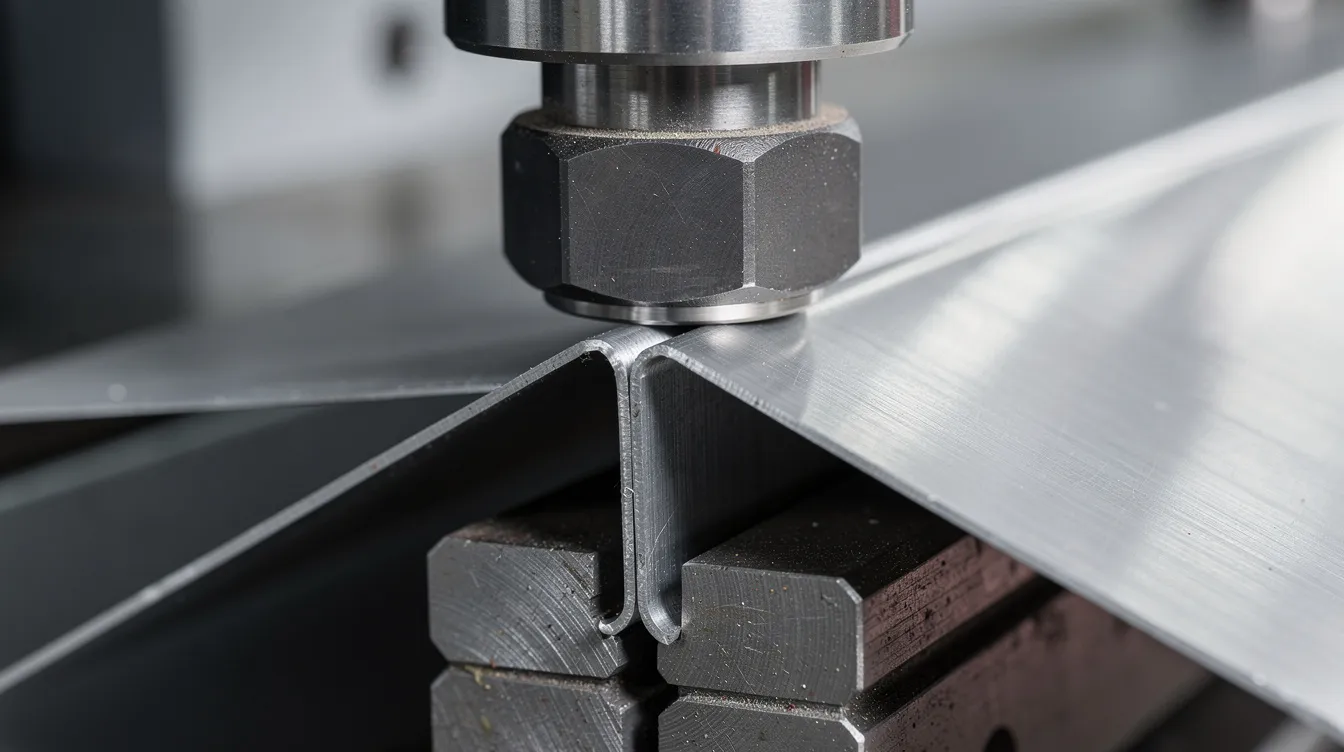
Bottom bending provides more accurate angles with less springback than air bending. The sheet is pressed until it fully contacts the bottom die, so the final angle is determined by tooling geometry rather than stroke alone.
-
Bottoming: requires 3–5× the tonnage of air bending; angle repeatability is excellent; suited for parts where ±0.3° or tighter is needed
-
Coining: uses high pressure to conform the metal precisely with minimal springback; press brakes can exert forces over 100 tons for bending steel; can achieve ±0.1° on angle
-
Coining may thin the material 3–10% in the bend zone and can leave surface imprints
-
Both methods demand matched tooling geometry and careful alignment
Use cases for bottoming and coining include tight tolerance medical device brackets, small aerospace components with critical bends, and any application where angle consistency across hundreds of bent parts is non-negotiable. The trade-off is higher tooling wear and longer setup.
Folding, Wiping, and Hand Tools
Folding and wiping methods clamp the sheet along the bend line and then swing a beam or wipe tool to form the flange. This approach works well for long, straight bends on panels and enclosures.
-
Folding produces less surface marking than press brake operations, making it suitable for decorative panels and pre-painted surfaces
-
Wiping dies are faster but can leave more scratches on the material
-
Common tools for light-duty or field work include hand seamers, bar folders, bench brakes, and improvised setups with angle iron and clamps
-
Manual sheet metal brakes are affordable for hobbyists and small workshops
-
Proper tooling and a stable workpiece are crucial for achieving precise bends even on simple setups
Anebon uses folding when parts have very long edges, pre-finished surfaces requiring a nice finished appearance, or geometries that would be awkward on a standard press brake.
Roll Bending and Three-Point Bending
Roll bending creates large-radius curves instead of sharp bends by passing sheet or plate through three or four adjustable rollers. This is the method of choice when you need to bend sheet metal into a circle or cylindrical shell.
-
Typical applications: ducts, housings, structural shells, architectural elements, and radiused profiles
-
Three-point bending setups use adjustable dies or crowning systems to correct deflection and produce precise long bends across the full bend length
-
Hole locations, slots, and weld seams must be planned early because rolling can distort features
-
Minimum achievable radius is typically several times the material thickness
Design Math: Bend Allowance, Bend Deduction, and K Factor
Getting the flat pattern right is the single most important step before cutting blanks. If the blank is the wrong size, the final part dimensions will be off regardless of how well you bend it. Bend radius depends on material properties and tooling geometry, and materials stretch during bending, affecting hole to edge distance.
-
Bend allowance (BA) – the arc length along the neutral axis consumed by the bend. Calculated with the following formula: BA = (π / 180) × bend angle × (inside radius + k factor × thickness)
-
Bend deduction (BD) – the difference between the sum of flange lengths measured to the theoretical sharp corner and the actual flat pattern length; it accounts for the material consumed by the bend
-
K factor – the ratio locating the neutral axis between the inner and outer surfaces of the sheet; typical range is 0.30–0.50 depending on material, radius, and bending method
Anebon uses CAD software with material- and tooling-specific bend tables rather than manual calculators, incorporating empirical data from test coupons to refine k factor values for each material batch, punch and die set, and cnc machine setup.
Flat Pattern Calculation in Practice
Here is how a design engineer or CAD system uses bend allowance to calculate flat pattern length from a 3D model:
-
Start with the desired shape: a bracket with two flanges and a web between them
-
Measure each flange length to the theoretical intersection point (the sharp corner if there were no radius)
-
Subtract the bend deduction for each bend, or equivalently add the bend allowance to the sum of flat segments between bend tangent points
-
The result is the flat blank length to be cut on the laser cutter
Consider a concrete example: a 2 mm thick 304 stainless steel bracket with two 90° bends, each at an inside radius of 2 mm. If you assume k factor = 0.50 instead of the actual value of approximately 0.45, the flat pattern error accumulates across both bends. Even a 5% shift in k factor on two bends can produce a blank that is measurably too long or too short, causing flanges to miss their target dimensions.
Anebon refines k factor values specific to material batches, bending tools, and machines to improve accuracy for repeat orders. This empirical approach is far more reliable than textbook defaults for production sheet metal parts.
Key Design Rules for Bending Sheet Metal
Good DFM practices reduce scrap, cost, and lead time. Using the correct bend radius reduces the risk of cracking and meets design requirements. A bend radius that is too tight can cause cracking in some materials, and thicker materials require larger bend radii, limiting design options.
-
Minimum inside bend radius: ≥ 1× material thickness for mild steel and soft aluminum; ≥ 1.5–2× for stainless steel grades; 2–3× for high-strength alloys
-
Keep holes and slots at least 2× material thickness from the bend line
-
Minimum flange length must clear the press brake tooling width (typically ≥ 4× thickness)
-
Maintain consistent bend radii and sheet thickness across a project to minimize tool changes and setup time
-
Bend-to-bend spacing must allow for tooling clearance, especially when forming box or channel sections
Managing Springback and Tolerances
Springback is the elastic recovery that causes a bent part to open slightly after the punch retracts. Springback typically amounts to 1–2° after bending for most common materials and setups, though springback varies; metals may relax by 5 to 10 degrees after bending in some high-strength or thick-material scenarios.
The following table summarizes typical springback ranges by material:
|
Material |
Typical Springback |
Recommended Compensation |
|---|---|---|
|
Mild steel |
1°–1.5° |
Overbend or CNC correction |
|
Stainless steel (304/316) |
3°–5° |
Bottoming, overbend, angle sensors |
|
Aluminum (5052, 6061) |
2°–3° |
Overbend, adjusted punch radius |
|
High-strength steel |
5°–10° |
Coining or aggressive overbend |
CNC press brake controllers compensate by overbending, using different punch radii, or employing real-time angle measurement systems. Bend angles have a standard tolerance of ±1° for general work, with ±0.5° achievable on precision setups and ±0.3° possible with bottoming. Bend length tolerances are typically ±0.20 mm per bend. Bending can produce parts with accuracy levels of ±0.05 mm on critical features when combined with precision laser cutting.
Features Near the Bent Edge
Placing features too close to a bend invites distortion, tearing, or tooling collisions. Material grain direction impacts bending ease and cracking risk during deformation, so grain orientation should be considered when laying out bends relative to features.
-
Keep holes at least 2× material thickness away from the bend line; increase this for brittle materials or tight radii
-
Add relief cuts (small notches or triangular cutouts) where tabs or flanges intersect bends to prevent tearing
-
Slots running parallel to a bend line should be terminated with a small radius to reduce stress concentration
-
Anebon’s DFM review flags features that risk distortion and proposes small geometry changes-moving a hole 1–2 mm, adding a relief notch-before production begins
DIY vs Industrial: How to Bend Metal Sheet Without a Brake
R&D engineers and small teams sometimes need to bend thin sheet metal prototypes in a basic workshop without a full-size brake. Here is how to approach it safely:
-
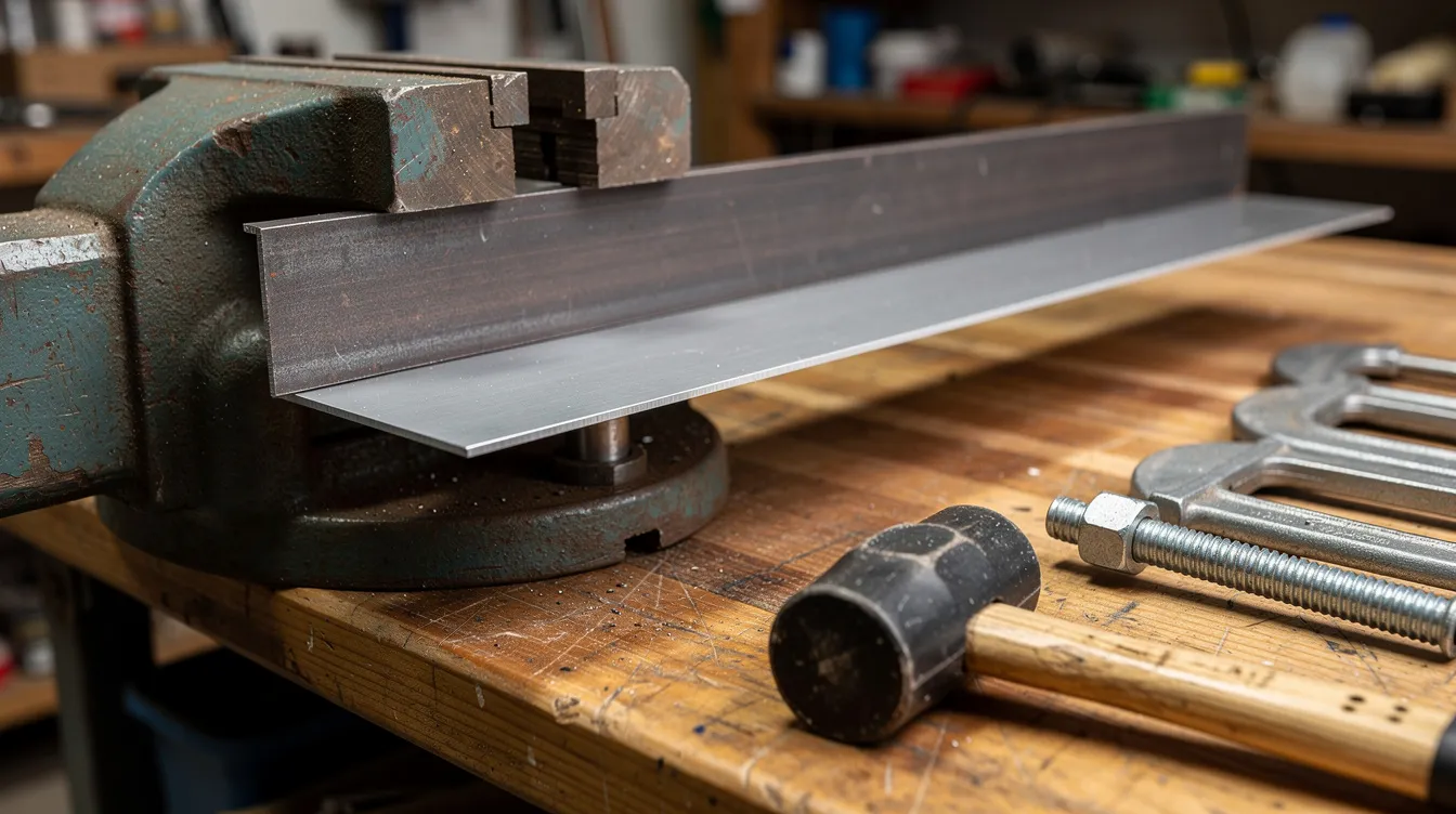
For thin aluminum or steel under approximately 1.5 mm, use a bench vise, two pieces of angle iron as straight edges, clamps, and a rubber mallet. Clamp the sheet firmly along the desired bend line and apply force gradually.
-
Bending can be done using a vice and form blocks shaped to match the desired bend angle.
-
Use a hammer to improve uneven bends in sheet metal, working gradually along the length.
-
Hand seamers work for short flanges and field modifications but offer poor precision and repeatability.
-
Heat can soften thick metal for easier bending, though this changes material properties and may affect surface finish.
-
A scrap piece of the same material should be used for test bends before committing to the actual part.
-
Think of this like bending cardboard: the concept is simple, but controlling the result requires practice and fixturing.
For production or tight tolerances, a CNC press brake and proper tooling are required. The automated process that industrial equipment provides is what separates prototype-quality from production-quality bent parts.
Laser-Cut Reliefs for Hand Bending
Adding relief cuts or bend “hinges” in laser-cut sheet metal allows manual bending without a full-size sheet metal brake. Relief cuts help bend sheet metal easily at home by reducing the stiffness at the bend line.
-
Common patterns: straight slots along the bend line, triangular cutouts at the ends of the bend, or perforation-like rows of small holes
-
These patterns control where the material folds and can approximate a consistent bend radius
-
Cautions: reduced stiffness at the bend, potential fatigue issues under cyclic loading, and visible relief patterns that may not suit cosmetic applications
-
Off the shelf hinges can sometimes replace laser-cut living hinges where strength or appearance is critical
Anebon can laser cut relief patterns and also provide standard press brake bending on the same part series, letting R&D teams compare both approaches during early-stage development.
Materials for Bending: Strength, Ductility, and Corrosion Resistance
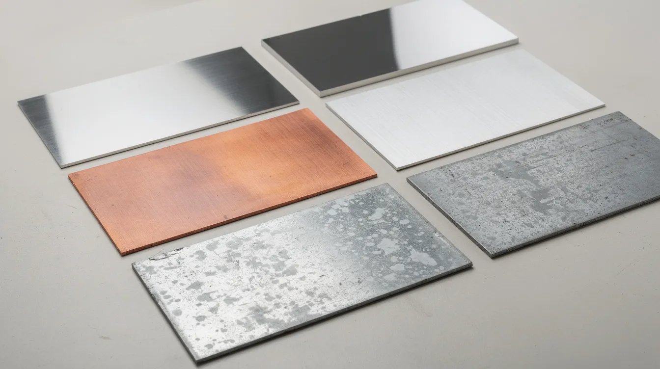
The material you choose determines minimum bend radii, springback behavior, surface finish requirements, and corrosion resistance. Bending can be performed on materials up to 8mm thick, though most precision OEM work stays in the 0.5–6 mm range. Here are the main materials Anebon works with:
-
Mild steel (Q235, A36, low-carbon grades) – mild steel is the most commonly used bending material; ductile, forgiving, moderate springback; minimum radius approximately 1× thickness; lower cost
-
Stainless steel (304, 316) – stainless steel contains at least 10.5% chromium for corrosion resistance; less ductile, higher springback (1.5–2× thickness minimum radius); work-hardens in the bend zone
-
Aluminum alloys (5052, 6061) – aluminum alloys can be bent to tight radii without cracking in soft tempers, though aluminum may require a larger bend radius to avoid breaking compared to steel in harder tempers like 6061-T6
-
Copper – copper is highly conductive and easily bent for electrical applications; requires care to avoid surface marking
-
Brass – brass is valued for its aesthetic appeal and ease of fabrication; good ductility for decorative components
-
Galvanized steel – galvanized steel has a zinc coating for improved corrosion resistance; bend before galvanizing when possible to avoid coating cracks
-
Sheet steel of different grades offers a wide range of strength and formability options
Bending can leave indentations or scratches on the material, so coating and finishing should generally happen after bending. If parts must be bent after coating, use flexible finishes and larger radii.
Choosing the Right Sheet Metal for Your Application
Application requirements drive material selection. Here are common scenarios for 2024–2026 OEM programs:
-
EV battery enclosures and thermal management – aluminum 5052 for weight reduction and thermal conductivity; may need anodizing for corrosion resistance
-
19-inch rackmount chassis and electronics housings – cold-rolled sheet steel or galvanized steel for cost and EMI shielding; powder coat finish
-
Medical device frames and lab equipment – stainless 304 or 316 for chemical resistance, cleanability, and sterilization compatibility
-
Robotics brackets and actuator mounts – mild steel or aluminum depending on weight and stiffness targets
-
Decorative panels and consumer products – brass or copper where appearance matters; aluminum where a nice finished anodized surface is needed
Anebon advises on balancing corrosion resistance, bendability, and cost for OEM programs from prototype through mass production. Temperature exposure, outdoor weather, cleaning chemicals, and fatigue cycles all influence the right choice for your sheet metal fabrication project.
Press Brake Technology and Tooling at Anebon
Modern CNC press brakes are the backbone of precision sheet metal bending. CNC bending can reduce manual labor and costs significantly compared with older manual setups.
-
Multi-axis backgauges position each flange precisely for multiple bends in a controlled forming sequence
-
Programmable crowning systems compensate for machine frame deflection on long parts
-
Off-line programming integrates with laser cutting data for seamless blank-to-bend workflows
-
Bending lengths up to several meters accommodate large cabinet panels and enclosures
-
Common tools include v shaped dies (standard and wide-opening), radius dies, gooseneck punches for box sections, hemming tools, and special tooling for joggles or offset bends
-
Digital simulations and bending databases reduce trial-and-error, particularly for new OEM parts produced for the first time
Quality Control and Tolerances in Bending
Anebon’s quality workflow ensures that parts produced meet drawing specifications consistently:
-
First-article inspection – prototype or pilot batch where bend angles, radii, and flat patterns are checked against the drawing before full production
-
In-process checks – digital angle gauges and height gauges verify bend angle and flange length periodically during the run
-
Final inspection – coordinate measuring machines (CMMs), optical comparators, and reference coupons confirm critical features
-
Traceability – material certificates and inspection reports accompany each shipment; ISO 9001:2015 and ISO 14001:2015 certifications support quality and environmental compliance
Engineers can specify tolerances on drawings knowing that ±0.5° angular and ±0.2–0.5 mm linear are achievable for standard work, with tighter values possible for critical dimensions.
Integrating Bending with Other Fabrication Processes
Bending rarely stands alone. It fits into a complete fabrication workflow alongside CNC laser cutting, CNC punching, hardware insertion, welding, cnc machine operations, and surface finishing.
-
Electronics enclosure – a single bent sheet replaces a multi-piece welded assembly: laser cut the blank with all holes and slots, bend into a U-channel or box, insert PEM fasteners, powder coat. Fewer welds mean lower cost, less distortion, and a cleaner surface.
-
Robotics bracket – laser cut from 3 mm aluminum, bend two flanges, then CNC mill precision mounting surfaces that must align after forming. The milling step after bending corrects any minor dimensional shifts from the bending process.
-
Medical device frame – 316 stainless, laser cut, multiple bends to form a rigid chassis, then passivation for corrosion resistance. Tight tolerances on bend angles ensure mating faces align without shimming.
These examples show how a well-planned desired shape can be achieved from a single flat blank, reducing welding, assembly, and weight while maintaining or improving structural performance.
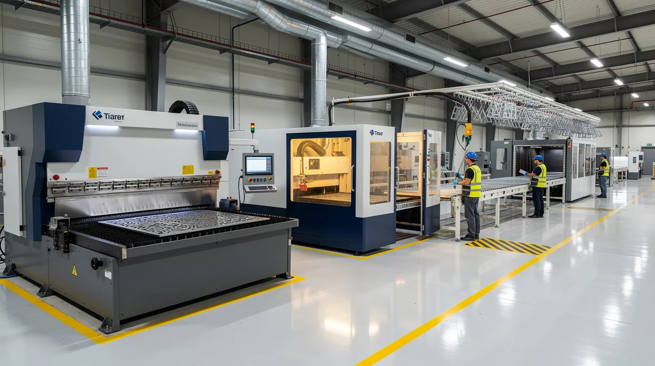
Cost, Lead Time, and DFM Support for OEM Projects
Understanding cost drivers helps you design parts that are both functional and economical to produce. The primary factors that influence pricing:
-
Material type and thickness of the material – harder or thicker materials require more tonnage, heavier tooling, and longer cycle times; this drives a lower cost advantage toward mild steel and standard aluminum for non-critical applications
-
Number of bends – each bend adds cycle time, and complex sequences with multiple bends may require careful bend ordering
-
Tooling changes – using the same die width and punch profile across a project cuts setup time; custom tools for unusual radii or joggles add cost
-
Part size – long bend lengths require larger machines with crowning systems; very small parts may need special fixturing
-
Tolerance requirements – tighter tolerances mean more measurement, potentially bottoming instead of air bending, and additional in-process inspection
-
Secondary operations – tapping, welding, hardware insertion, and finishing all add time
CNC blanking via laser cutting plus air bending keeps tooling costs far below hard tooling like stamping dies, making this approach ideal for low-to-medium volume OEM production. Typical lead times at Anebon run 1–2 weeks for prototypes and scale down per-part as volumes increase, assuming common materials are in stock.
Anebon’s DFM feedback covers bend radii, flange sizes, hole locations, and material selection before quoting-catching issues early saves redesign cycles and avoids costly prototype failures.
When to Involve Anebon in Your Sheet Metal Bending Project
The earlier you involve your fabrication partner, the fewer surprises you encounter in production. For complex bent parts, tight tolerance assemblies, or challenging materials, engage Anebon before finalizing CAD.
-
Provide 3D CAD files (STEP or IGES) along with 2D drawings that include bend notes: inside radius, bend angle, flange lengths, and the desired bend for each feature
-
Include material specification (alloy, temper, sheet thickness), required finish or coating, and any certification requirements
-
Share annual volume estimates and batch sizes so Anebon can recommend the right bending method and tooling strategy
-
Communicate functional requirements-stiffness, corrosion resistance, weight targets, mating interface tolerances-so the team can recommend materials and form strategies that balance performance and cost
-
Ask about integrating bending with other processes: laser cutting, CNC machining, welding, and surface treatment in a single production flow
Whether you are prototyping a two-point bracket or scaling a complex enclosure with a dozen bends, Anebon’s team can review your design, flag manufacturability risks, and deliver parts that meet your specifications. Request a DFM review or quote to get started on your next project.