The art of boosting machine tool accuracy with backlash and pitch compensation
The efficiency of CNC machine tool equipment is closely tied to its accuracy, making it a key priority for companies when procuring or developing such tools. However, the accuracy of most new machine tools often falls short of the required standards upon leaving the factory. Additionally, the occurrence of mechanical running-in and wear during prolonged use emphasizes the vital need for adjusting the accuracy of CNC machine tools to ensure optimal production performance.
1. Backlash compensation
Mitigating BacklashWithin CNC machine tools, errors stemming from the reverse dead zones of the driving components on the feed transmission chain of each coordinate axis and the reverse clearance of each mechanical motion transmission pair lead to deviations as each coordinate axis transitions from forward to reverse motion. This deviation, also known as reverse clearance or lost momentum, can significantly impact the positioning accuracy and repetitive positioning accuracy of the machine tool when semi-closed-loop servo systems are utilized. Furthermore, the gradual increase in kinematic pair clearances due to wear over time leads to a corresponding increase in reverse deviation. Therefore, regular measurement and compensation for the reverse deviation of each coordinate axis of the machine tool are imperative.
Measuring Backlash
To assess reverse deviation, start within the travel range of the coordinate axis. Firstly, establish a reference point by moving a set distance in either the forward or reverse direction. Following this, issue a specific movement command in the same direction to cover a certain distance. Next, proceed to move the same distance in the opposite direction and determine the variance between the reference and stop positions. Typically, multiple measurements (often seven) are conducted at three locations near the midpoint and both extremes of the travel range. The average value is then calculated at each location, with the maximum among these averages used as the measurement for reverse deviation. It is essential to move a specific distance during measurements to accurately determine the reverse deviation value.
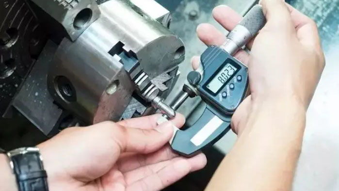
When assessing the reverse deviation of a linear motion axis, it is common to employ a dial indicator or dial gauge as the measurement tool. If circumstances allow, a dual-frequency laser interferometer can also be utilized for this purpose. When using a dial indicator for measurements, it is essential to ensure that the meter base and stem do not extend excessively, as a long cantilever during measurement can cause the meter base to move due to force, leading to inaccurate readings and unrealistic compensation values.
Implementing a programming method for measurement can enhance the convenience and accuracy of the process. For example, to assess the reverse deviation of the X-axis on a three-coordinate vertical machine tool, the process can begin by pressing the meter against the cylindrical surface of the spindle, followed by running a designated program for measurement.
N10G91G01X50F1000; move the workbench to the right
N20X-50; the worktable moves to the left to eliminate the transmission gap
N30G04X5; pause for observation
N40Z50; Z-axis raised and out of the way
N50X-50: Workbench moves to the left
N60X50: Workbench moves right and resets
N70Z-50: Z axis reset
N80G04X5: Pause for observation
N90M99;
It is important to note that the measured results may vary based on different operating speeds of the workbench. Generally, the measured value at low speed is greater than that at high speed, particularly when the machine tool axis load and motion resistance are substantial. At lower speeds, the worktable moves at a slower pace, resulting in less likelihood of overshoot and overtravel, hence yielding a higher measured value. On the other hand, at higher speeds, overshoot and overtravel are more likely to occur due to the faster worktable speed, resulting in a smaller measured value. The measurement approach for the reverse deviation of the rotary motion axis follows a similar process to that of the linear axis, with the only difference being the instrument used for detection.
Compensating for Backlash
Numerous CNC machine tools made in the country exhibit positioning accuracy of over 0.02mm, yet lack the capability for compensation. In certain situations, programming techniques can be employed to accomplish one-way positioning and eliminate backlash for such machine tools. As long as the mechanical component remains unchanged, initiating interpolation processing is feasible once the low-speed, one-way positioning reaches the starting point for interpolation. When encountering a reverse direction during interpolation feed, formally interpolating the reverse clearance value has the potential to enhance the accuracy of interpolation processing and effectively meet the cnc milled part‘s tolerance requirements.
For other varieties of CNC machine tools, multiple memory addresses in the CNC device are typically designated to store the backlash value of each axis. When an axis of the machine tool is directed to change its movement direction, the CNC device will automatically retrieve the backlash value of the axis, which compensates and rectifies the coordinate displacement command value. This ensures that the machine tool can be precisely positioned at the command position and mitigates the adverse impact of reverse deviation on the accuracy of the machine tool.
Typically, CNC systems are equipped with a single available backlash compensation value. Balancing high- and low-speed motion precision, as well as addressing mechanical improvement, becomes challenging. Moreover, the reverse deviation value measured during rapid motion can only be utilized as the input compensation value. Consequently, achieving equilibrium between rapid positioning accuracy and interpolation accuracy during cutting proves to be difficult.
For CNC systems such as FANUC0i and FANUC18i, there are two available forms of backlash compensation for rapid motion (G00) and slow-speed cutting feed motion (G01). Depending on the chosen feeding method, the CNC system automatically selects and utilizes distinct compensation values to achieve enhanced processing precision.
The backlash value A, obtained from G01 cutting feed motion, should be entered into parameter NO11851 (the G01 trial speed should be determined based on the commonly used cutting feed speed and machine tool characteristics), while the backlash value B from G00 should be inputted into parameter NO11852. It is important to note that if the CNC system seeks to execute separately specified reverse backlash compensation, the fourth digit (RBK) of parameter number 1800 must be set to 1; otherwise, separately specified reverse backlash compensation will not be carried out. Gap compensation. G02, G03, JOG, and G01 all employ the same compensation value.
Compensation for Pitch Errors
The precision positioning of CNC machine tools involves the evaluation of the accuracy with which the movable components of the machine tool can reach under the command of the CNC system. This precision plays a crucial role in distinguishing CNC machine tools from conventional ones. Aligned with the geometric precision of the machine tool, it significantly impacts the cutting precision, particularly in hole machining. The pitch error in hole drilling has a substantial impact. The ability of a CNC machine tool to assess its processing precision relies on the achieved positioning accuracy. Therefore, the detection and rectification of the positioning accuracy of CNC machine tools are essential measures to ensure processing quality.
Pitch Measurement Process
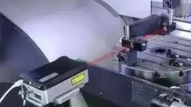
Presently, the primary method for evaluating and handling machine tools is the use of dual-frequency laser interferometers. These interferometers operate on the principles of laser interferometry and utilize the real-time laser wavelength as the reference for measurement, thereby enhancing measurement precision and expanding the range of applications.
The process for detecting pitch is as follows:
- Install the dual-frequency laser interferometer.
- Position an optical measuring device along the axis of the machine tool that requires measurement.
- Align the laser head to ensure that the measurement axis is either parallel or collinear with the movement axis of the machine tool, thus pre-aligning the optical path.
- Input the measurement parameters once the laser reaches its operating temperature.
- Execute the prescribed measurement procedures by moving the machine tool.
- Process the data and generate the results.
Pitch Error Compensation and Automatic Calibration
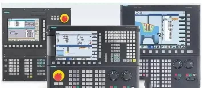
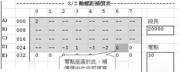
When the measured positioning error of a CNC machine tool surpasses the allowable range, there is a need to correct the error. One prevalent approach involves computing the pitch error compensation table and manually inputting it into the machine tool’s CNC system to rectify the positioning error. However, manual compensation can be time-consuming and prone to errors, especially when dealing with numerous compensation points across three or four axes of the CNC machine tool.
To streamline this process, a solution has been developed. By linking the computer and the machine tool’s CNC controller through the RS232 interface and leveraging automatic calibration software created in VB, it is possible to synchronize the laser interferometer and the CNC machine tool. This synchronization enables the automatic detection of the CNC machine tool’s positioning accuracy and the implementation of automatic pitch error compensation. The compensation method includes:
- Creating a backup of the existing compensation parameters in the CNC control system.
- Generating a machine tool CNC program for point-by-point positioning accuracy measurement using the computer, which is then transmitted to the CNC system.
- Automatically measuring the positioning error of each point.
- Generating a new set of compensation parameters based on the predetermined compensation points and transmitting them to the CNC system for automatic pitch compensation.
- Verifying the accuracy repeatedly.
These specific solutions aim to enhance the accuracy of CNC machine tools. Nevertheless, it is essential to note that the accuracy of different CNC machine tools may vary. As a result, machine tools should be calibrated according to their individual circumstances.
If error compensation is not performed on the machine tool, what impact will it have on the CNC parts produced?
If error compensation is overlooked on a machine tool, it can result in discrepancies in the CNC parts manufactured. For instance, if the machine tool has an unadjusted positioning error, the true position of the tool or workpiece may diverge from the programmed position specified in the CNC program, leading to dimensional inaccuracies and geometric errors in the produced parts.
For example, if a CNC milling machine has an unadjusted positioning error in the X-axis, the milled slots or holes in the workpiece may be misaligned or have incorrect dimensions. Similarly, in a lathe operation, unadjusted positioning errors could cause inaccuracies in the diameter or length of turned parts. These discrepancies may lead to non-conforming parts that fail
Anebon will make each hard work to become excellent and excellent, and speed up our measures for standing from the rank of intercontinental top-grade and high-tech enterprises for China Gold Supplier for OEM, Custom cnc machining service, Sheet Metal fabrication service, milling services. Anebon will do your personalized purchase to meet your own satisfactory! Anebon’s business sets up several departments, including output department, revenue department, excellent control department and sevice center, etc.
Factory Supply China Precision Part and Aluminum Part, You can let Anebon know your idea to develop unique design for your own model to prevent too much similar parts in the market! We are going to give our best service to satisfy all your needs! Remember to contact Anebon right away!
