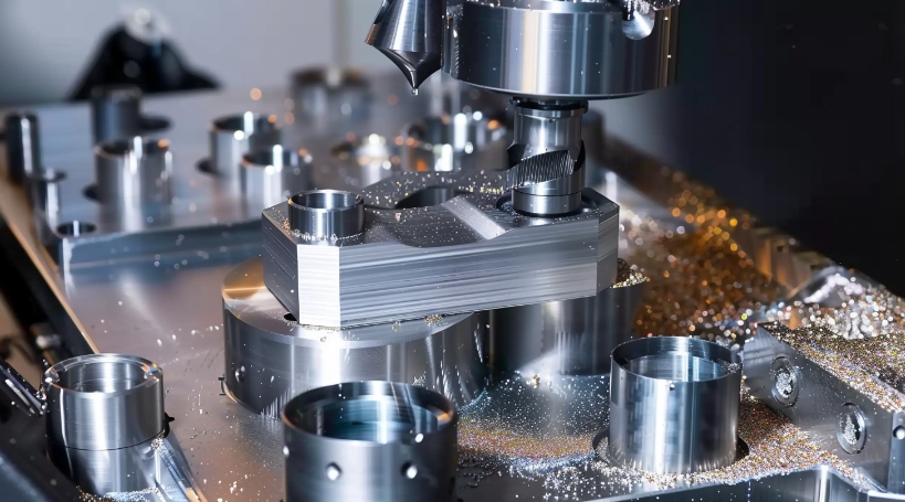
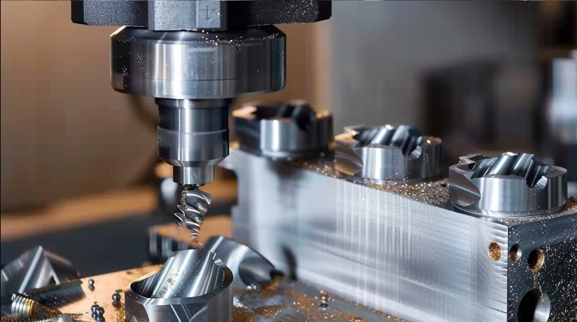
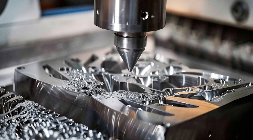
Study Sheds Light on Hurdles in the Processing of Stainless Steel Materials
What are the obvious advantages of CNC parts using stainless steel as raw material compared to steel and aluminum alloys?
Stainless steel is an excellent choice for a variety of applications due to its unique properties. It is highly resistant to corrosion, which makes it ideal for use in harsh environments like marine, aerospace, and chemical industries. Unlike steel and aluminum alloys, stainless steel does not rust or corrode easily, which increases the longevity and reliability of the parts.
Stainless steel is also incredibly strong and durable, comparable to steel alloys and even surpassing the strength of aluminum alloys. This makes it a great option for applications that require robustness and structural integrity, such as automotive, aerospace, and construction.
Another benefit of stainless steel is that it maintains its mechanical properties at both high and low temperatures. This characteristic makes it suitable for applications where extreme temperature variations are encountered. In contrast, aluminum alloys may experience reduced strength at high temperatures, and steel may be susceptible to corrosion at elevated temperatures.
Stainless steel is also inherently sanitary and straightforward to clean. This makes it an ideal choice for applications in the medical, pharmaceutical, and food processing industries where cleanliness is essential. Unlike steel, stainless steel does not require additional coatings or treatments to maintain its hygienic properties.
Although stainless steel has many advantages, its processing difficulties cannot be ignored.
The difficulties in processing stainless steel materials mainly include the following aspects:
1. High cutting force and high cutting temperature
This material possesses high strength and significant tangential stress, and it undergoes significant plastic deformation during cutting, which leads to a significant cutting force. Moreover, the material has poor thermal conductivity, causing the cutting temperature to rise. The high temperature is often concentrated in the narrow area near the cutting edge of the tool, leading to an accelerated wear of the tool.
2. Severe work hardening
Austenitic stainless steel and some high-temperature alloy stainless steels have an austenitic structure. These materials have a higher tendency to work harden during cutting, typically several times more than ordinary carbon steel. As a result, the cutting tool operates in the work-hardened area, which shortens the tool’s lifespan.
3. Easy to stick to the knife
Both austenitic stainless steel and martensitic stainless steel share the characteristics of producing strong chips and generating high cutting temperatures while being processed. This can result in the adhesion, welding, and other sticking phenomena that may interfere with the surface roughness of the machined parts.
4. Accelerated tool wear
The materials mentioned above contain high-melting-point elements, are highly malleable, and generate high cutting temperatures. These factors lead to accelerated tool wear, necessitating frequent tool sharpening and replacement. This negatively impacts production efficiency and increases tool usage costs. To combat this, it is recommended to reduce the cutting line speed and feed. Additionally, it is best to use tools specifically designed for processing stainless steel or high-temperature alloys, and to use internal cooling when drilling and tapping.
Stainless steel parts processing technology
Through the above analysis of processing difficulties, the processing technology and related tool parameter design of stainless steel should be quite different from ordinary structural steel materials. The specific processing technology is as follows:
1. Drilling processing
When drilling stainless steel materials, hole processing can be difficult due to their poor thermal conductivity and small elastic modulus. To overcome this challenge, appropriate tool materials should be selected, reasonable geometric parameters of the tool should be determined, and the cutting amount of the tool should be set. Drill bits made of materials such as W6Mo5Cr4V2Al and W2Mo9Cr4Co8 are recommended for drilling these types of materials.
Drill bits made of high-quality materials have some disadvantages. They are relatively expensive and difficult to purchase. When using the commonly used W18Cr4V standard high-speed steel drill bit, there are some shortcomings. For example, the vertex angle is too small, the chips produced are too wide to be discharged out of the hole in time, and the cutting fluid is unable to cool the drill bit quickly. Moreover, stainless steel, being a poor thermal conductor, causes concentration of the cutting temperature on the cutting edge. This can easily result in burns and chipping of the two flank surfaces and the main edge, reducing the service life of the drill bit.
1) Tool geometric parameter design When drilling with a W18Cr4V When using an ordinary high-speed steel drill bit, the cutting force and temperature are mainly concentrated on the drill tip. To improve the durability of the cutting part of the drill bit, we can increase the vertex angle to about 135°~140°. This will also reduce the outer edge rake angle and narrow the drilling chips to make it easier to remove them. However, increasing the vertex angle will make the chisel edge of the drill bit wider, resulting in higher cutting resistance. Therefore, we must grind the chisel edge of the drill bit. After grinding, the bevel angle of the chisel edge should be between 47° to 55°, and the rake angle should be 3°~5°. While grinding the chisel edge, we should round the corner between the cutting edge and the cylindrical surface to increase the strength of the chisel edge.
Stainless steel materials have a small elastic modulus, meaning that the metal under the chip layer has large elastic recovery and work hardening during processing. If the clearance angle is too small, the wear of the drill bit flank surface will be accelerated, the cutting temperature will be increased, and the life of the drill bit will be reduced. Therefore, it is necessary to increase the relief angle appropriately. However, if the relief angle is too large, the main edge of the drill bit will become thin, and the rigidity of the main edge will be reduced. A relief angle of 12° to 15° is generally preferred. In order to narrow the drill chips and facilitate chip removal, it is also necessary to open staggered chip grooves on the two flank surfaces of the drill bit.
2) When selecting the cutting amount for drilling, the selection of the When it comes to cutting, the starting point should be to reduce the cutting temperature. High-speed cutting results in increased cutting temperature, which in turn aggravates tool wear. Therefore, the most important aspect of cutting is to select the appropriate cutting speed. Generally, the recommended cutting speed is between 12-15m/min. The feed rate, on the other hand, has little effect on tool life. However, if the feed rate is too low, the tool will cut into the hardened layer, which will worsen wear. If the feed rate is too high, the surface roughness will also worsen. Considering the above two factors, the recommended feed rate is between 0.32 and 0.50mm/r.
3) Cutting fluid selection: In order to reduce the cutting temperature during drilling, emulsion can be used as the cooling medium.
2. Reaming processing
1) When reaming stainless steel materials, carbide reamers are commonly used. The reamer’s structure and geometric parameters differ from those of ordinary reamers. To prevent chip clogging during reaming and enhance the strength of the cutter teeth, the number of reamer teeth is generally kept relatively low. The rake angle of the reamer is usually between 8° to 12°, although in some specific cases, a rake angle of 0° to 5° can be used to achieve high-speed reaming. The clearance angle is generally around 8° to 12°.
The main declination angle is chosen depending on the hole. Generally, for a through hole, the angle is 15° to 30°, while for a non-through hole, it is 45°. To discharge chips forward when reaming, the edge inclination angle can be increased by about 10° to 20°. The blade width should be between 0.1 to 0.15mm. The inverted taper on the reamer should be larger than that of ordinary reamers. The carbide reamers are generally 0.25 to 0.5mm/100mm, while high-speed steel reamers are 0.1 to 0.25mm/100mm in terms of their taper.
The correction part of the reamer is generally 65% to 80% of the length of ordinary reamers. The cylindrical part’s length is usually 40% to 50% of that of ordinary reamers.
2) When reaming, it is important to choose the right feed amount, which should be between 0.08 to 0.4mm/r, and cutting speed, which should range between 10 to 20m/min. The rough reaming allowance should be between 0.2 to 0.3mm, while the fine reaming allowance should be between 0.1 to 0.2mm. It is recommended to use carbide tools for rough reaming, and high-speed steel tools for fine reaming.
3) When selecting the cutting fluid for reaming stainless steel materials, total loss system oil or molybdenum disulfide can be used as the cooling medium.
3. Boring processing
1) When selecting tool material for processing stainless steel parts, it is important to consider the high cutting force and temperature. Carbides with high strength and good thermal conductivity, such as YW or YG carbide, are recommended. For finishing, YT14 and YT15 carbide inserts may also be used. Ceramic material tools can be utilized for batch processing. However, it is important to note that these materials are characterized by high toughness and severe work hardening, which will cause the tool to vibrate and may result in microscopic vibrations on the blade. Therefore, when selecting ceramic tools for cutting these materials, microscopic toughness should be taken into consideration. Currently, α/βSialon material is a better choice because of its excellent resistance to high-temperature deformation and diffusion wear. It has been successfully used in cutting nickel-based alloys, and its service life far exceeds Al2O3-based ceramics. SiC whisker-reinforced ceramics is also an effective tool material for cutting stainless steel or nickel-based alloys.
CBN (cubic boron nitride) blades are recommended for processing quenched parts made of these materials. CBN is second only to diamond in terms of hardness, with a hardness level that can reach 7000~8000HV. It has high wear resistance and can withstand high cutting temperatures up to 1200°C. Furthermore, it is chemically inert and has no chemical interaction with iron group metals at 1200 to 1300°C, making it ideal for processing stainless steel materials. Its tool life can be dozens of times longer than that of carbide or ceramic tools.
2) The design of tool geometric parameters is critical for achieving efficient cutting performance. Carbide tools require a larger rake angle to ensure a smooth cutting process and longer tool life. The rake angle should be around 10° to 20° for rough machining, 15° to 20° for semi-finishing, and 20° to 30° for finishing. The main deflection angle should be chosen based on the process system’s rigidity, with a range of 30° to 45° for good rigidity and 60° to 75° for poor rigidity. When the length-to-diameter ratio of the workpiece exceeds ten times, the main deflection angle can be 90°.
When boring stainless steel materials with ceramic tools are used, a negative rake angle is generally used for cutting, ranging from -5° to -12°. This helps strengthen the blade and takes full advantage of the high compressive strength of ceramic tools. The relief angle’s size directly affects tool wear and blade strength, with a range of 5° to 12°. Changes in the main deflection angle affect the radial and axial cutting forces, as well as the cutting width and thickness. Since vibration can be detrimental to ceramic cutting tools, the main deflection angle should be chosen to reduce vibration, usually in the range of 30° to 75°.
When CBN is used as the tool material, the tool geometric parameters should include a rake angle of 0° to 10°, a relief angle of 12° to 20°, and a main deflection angle of 45° to 90°.
3) When sharpening the rake surface, it is important to keep the roughness value small. This is because when the tool has a small roughness value, it helps in reducing the flow resistance of cutting chips and avoids the problem of chips sticking to the tool. To ensure a small roughness value, it is recommended to carefully grind the front and rear surfaces of the tool. This will also help in avoiding chips sticking to the knife.
4) It’s important to keep the cutting edge of the tool sharp in order to reduce work hardening. Additionally, the feed amount and amount of back-cutting should be reasonable to avoid the tool from cutting into the hardened layer, which could negatively impact the tool’s lifespan.
5) It is important to pay attention to the grinding process of the chip breaker when working with stainless steel. These chips are known for their strong and tough characteristics, so the chip breaker on the rake surface of the tool should be properly ground. This will make it easier to break, hold, and remove chips during the cutting process.
6) When cutting stainless steel, it’s recommended to use low speed and large feed amounts. For boring with ceramic tools, selecting the right cutting amount is crucial for optimal performance. For continuous cutting, the cutting amount should be chosen based on the relationship between wear durability and cutting amount. For intermittent cutting, the appropriate cutting amount should be determined based on the tool breakage pattern.
Since ceramic tools have excellent heat and wear resistance, the impact of cutting amount on tool wear life is not as significant as with carbide tools. In general, when using ceramic tools, the feed rate is the most sensitive factor for tool breakage. Therefore, when boring stainless steel parts, try to select a high cutting speed, a large back cutting amount, and a relatively small advance, based on the workpiece material and subject to the machine tool power, process system stiffness, and blade strength.
7) When working with stainless steel, it is important to choose the right cutting fluid to ensure successful boring. Stainless steel is prone to bonding and has poor heat dissipation, so the cutting fluid selected must have good bonding resistance and heat dissipation properties. For example, a cutting fluid with a high chlorine content can be used.
Additionally, there are mineral oil-free, nitrate-free aqueous solutions available that have good cooling, cleaning, anti-rust, and lubricating effects, such as the H1L-2 synthetic cutting fluid. By using the appropriate cutting fluid, the difficulties associated with stainless steel processing can be overcome, resulting in improved tool life during drilling, reaming, and boring, reduced tool sharpening and changes, improved production efficiency, and higher quality hole processing. This can ultimately reduce labor intensity and production costs while achieving satisfactory results.
At Anebon, our idea is to prioritize quality and honesty, provide sincere assistance, and strive for mutual profit. We aim to consistently create excellent turned metal parts and micro CNC milling parts. We value your inquiry and will respond to you as soon as possible.


