Mastering the Sheet Metal Bend: Techniques for Precision and Strength
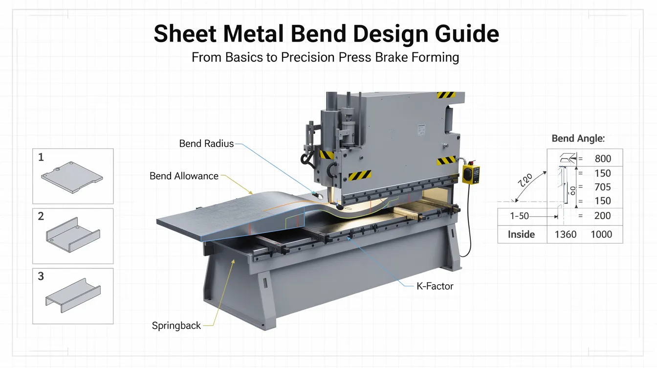
Sheet Metal Bend Design Guide: From Basics to Precision Press Brake Forming
Introduction to Sheet Metal Bending
Bending sheet metal is a foundational manufacturing process that transforms flat stock into functional geometry through permanent deformation. The bending process deforms flat metal sheets into specific angles or curves, and it is used across industries including aerospace bracket production, medical device housings, robotics frames, and electrical enclosures and automotive components. For each of these applications, accurate bend radius, correct bend allowance, and predictable flat pattern length determine whether a finished part fits its assembly or gets scrapped.
This guide is written from the perspective of Anebon Metal Products Limited, a precision sheet metal fabricator based in Dongguan, China, serving overseas OEMs since 2010. Anebon’s engineers review hundreds of sheet metal parts per month for manufacturability, and the design rules described here reflect what those reviews catch most often.
The sections that follow cover bend calculation concepts (K factor, bend deduction), practical design rules (minimum flange length, bend relief, hole placement), and the most common bending methods (air bending, rotary bending, roll bending, and others). Each section includes concrete numeric guidance tied to real material and thickness values.
What Is a Sheet Metal Bend? (Core Concept Explained First)
A sheet metal bend is the result of plastically deforming a flat sheet beyond its yield strength so it holds a new shape without external force. Plastic deformation occurs when the metal is bent past its elastic limit; the material on the inner surface compresses while the outer surface stretches. Press brakes, folding machines, punch presses, and rollers all accomplish this, though the press brake paired with a V die is the most common setup for angular bends.
Three geometric features define every bend. The inside bend radius is measured at the concave inner surface. The outside radius sits at the convex face and equals the inner radius plus the material thickness. Between them lies the neutral axis, the plane through the sheet thickness where the material experiences neither tension nor compression. The neutral axis location controls how much the sheet elongates during forming, which in turn drives every bending calculation downstream.
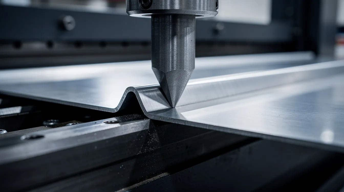
Bending increases stiffness without adding material. A 90° flange on a 1.5 mm mild steel bracket resists deflection that would require a flat surface parallel to the load direction at twice the gauge to match. This is why enclosures, channels, and mounting flanges appear in nearly every sheet metal design. Springback, the tendency of metal to return slightly toward its original shape after bending, means the desired angle on the drawing and the angle the operator programs are not the same number; operators often compensate for springback by slightly over-bending the material, sometimes referred to as having the part over bent by a calculated amount.
Anebon uses CNC press brakes with typical forming tolerances of ±0.5° on bend angle and ±0.1 mm on bend line location under controlled conditions. These numbers hold for standard tooling setups with consistent material batches.
Fundamental Bend Geometry: Neutral Axis, K Factor, Bend Allowance, Bend Deduction
Four values connect a 3D bent part to its flat pattern. Misunderstanding any one of them produces parts with wrong flange dimensions, misaligned holes, or assembly interference. Many variables affect these calculations, including material type, sheet thickness, tooling, and bending method.
The neutral axis is the stress-free line through the thickness that neither stretches nor compresses during a sheet metal bend. In tight-radius bends, it shifts toward the inner surface; in gentle curves, it stays closer to the center.
The K factor expresses where the neutral axis sits as a fraction of total thickness: K = (distance from inner surface to neutral axis) / thickness. A specific K factor for a given material and process typically ranges from 0.3 to 0.5. Mild steel air-bent at a radius equal to its thickness lands around 0.44. Softer aluminum alloys sit near 0.38 to 0.42.
Bend allowance is the length of the arc of the neutral line within the bend region. For a 90° bend in 2 mm mild steel with an inside radius of 2 mm and K = 0.44: BA = (π/180) × 90 × (2 + 0.44 × 2) ≈ 4.53 mm. This arc length gets added to the flat lengths of adjacent flanges when calculating the flat pattern length.
Bend deduction accounts for material stretching during bending. It is the value subtracted from the sum of flange lengths to yield the correct flat blank size. For the same 2 mm mild steel example, BD falls in the range of 4 to 6 mm depending on die opening and exact radius. Proper calculations for bend allowance and K-factor are essential for accurate dimensions.
Anebon’s CAD/CAM systems calculate these values automatically per bend, but engineers still verify outputs, especially when customers change material batches or use non-standard setups.
Bending Methods: Air Bending, Bottoming, Coining, Rotary and Roll Bending
Different bending techniques include air bending, bottoming, coining, and roll bending, among others. Each trades off between accuracy, tonnage, surface finish, and cost. Tool selection plays a crucial role in achieving accurate bend angles and preventing damage across all of them. Material properties such as type and thickness affect the bending process and which method applies best.
Air Bending
V-bending is the most common sheet metal bending method, and air bending is its most flexible variant. The punch pushes the sheet into the V die but does not bottom out; the bend angle is controlled by how far the punch descends. Air bending allows flexibility in bend angles and tolerances, with a typical angle tolerance of ±1° to ±2°.
The resulting bend radius is mainly a function of die opening and material thickness rather than the punch nose radius. A wider die opening produces a larger bend radius. Anebon relies on air bending for most stainless steel and mild steel parts between about 0.5 mm and 6 mm material thickness, covering the majority of OEM bracket, enclosure, and panel work.
Bottoming (Bottom Bending)
Bottoming forces the sheet fully against the die’s angle, conforming the material to the tooling geometry. Bottoming provides higher accuracy and less springback compared to air bending because the material is pressed into a defined shape rather than sprung into an approximated one. The trade-off is higher tonnage, sometimes two to three times that of air bending for the same part.
Anebon applies bottoming when parts have tight-tolerance mating interfaces, sealed enclosure joints, or OEM assemblies where consistent bend angle across a run matters more than tooling cost. Surface marking from the die is more likely, so parts destined for visible surfaces may need further finishing.
Coining
Coining is a high-pressure bending method for precision parts. The punch applies enough force to thin and imprint the material at the bend line, virtually eliminating springback. Press tonnage can be five to eight times that of air bending for the same thickness.
Anebon recommends coining for micro brackets, small electronic shields, and precision clips where the desired angle must hold within ±0.5° or tighter. Higher tool wear and energy cost limit coining to special situations rather than standard production bends.
Rotary Bending
Rotary bending produces sharp bends without scratching surfaces. A rotating cylindrical die rolls against the sheet to form the bend area, leaving almost no marking. This makes it ideal for pre-painted, anodized aluminum, or decorative stainless steel panels where surface integrity on visible faces is non-negotiable.
Rotary bending can achieve angles over 90° and form tight flanges near other features. Anebon uses it selectively where customers specify strict cosmetic requirements.
Roll Bending
Rolling uses multiple rollers to form smooth continuous curves or large-radius shapes. Roll bending uses rollers, typically in three-roll or four-roll configurations, to create cylindrical shapes, HVAC ducts, structural channels, and architectural panels. The curl radius depends on roller spacing, material stiffness, and sheet thickness.
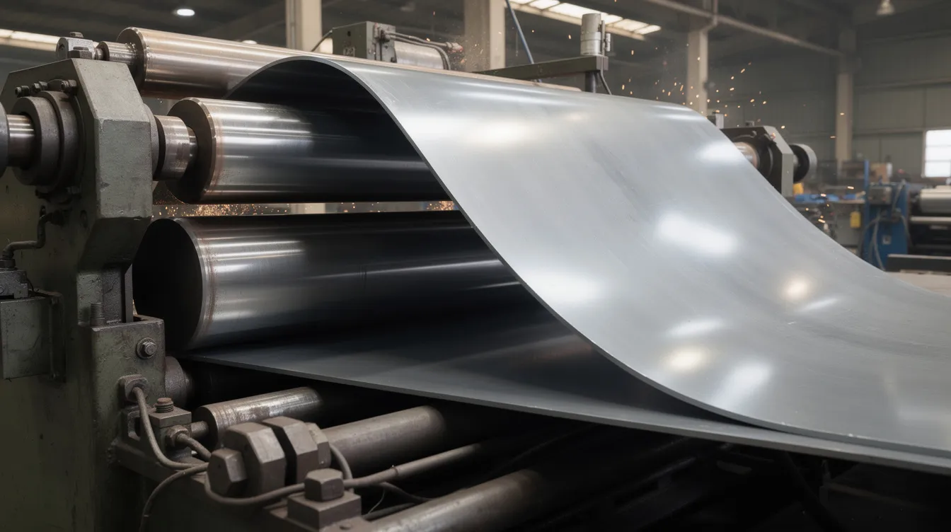
Pre-punched holes or cutouts must sit far enough from the bend line to avoid distortion, typically several multiples of thickness. Anebon assesses feasibility based on part length, target radius, and material, covering thicker materials from 1 mm sheet up through plate depending on roll capacity.
Key Design Rules for Sheet Metal Bends
These design rules form a checklist that Anebon’s engineers use during DFM reviews. Violations caught before laser cutting save material, time, and cost.
-
Uniform wall thickness is crucial for sheet metal parts. Mixing different thicknesses in one bent part complicates tooling, K factor calculation, and bend allowance accuracy. Inconsistent thickness can lead to stress concentrations and unpredictable forming behavior.
-
Bend radii must equal or exceed material thickness to prevent cracking. Harder tempers or alloys (6061-T6 aluminum, spring steel) need larger bend radii.
-
The minimum flange length must clear the die shoulders and back-gauge; parts with flanges shorter than about 4T + R risk dropping into the die or tilting during forming.
-
Holes should be at least 2.5 times the sheet thickness from bends. Closer placement causes feature distortion: holes elongate, slots skew, threads lose accuracy.
-
Bend reliefs prevent tearing and should match material thickness in width, with depth at least equal to the inside radius plus thickness.
-
Bends should be spaced adequately to avoid deformation and tool collisions during successive forming operations.
-
Grain direction matters: bending perpendicular to grain reduces cracking risk.
All these rules feed into Anebon’s DFM review; engineers recommend adjustments to customer drawings before production begins.
Minimum Bend Radius and Material Thickness Guidelines
The inside radius relative to sheet thickness is the single largest factor in whether a bend cracks or forms cleanly. The minimum bend radius should equal the material thickness for ductile alloys, and bending perpendicular to the grain direction reduces the risk of cracking.
-
For 1.0 to 3.0 mm mild steel, minimum inner radius ≈ 1.0T works for most bends across the grain.
-
Stainless steel (304, 316) and aluminum 6061-T6 need 1.5T to 2.0T minimum radius due to work hardening and lower ductility. See Anebon’s guide on how to bend aluminum sheet metal for alloy-specific advice.
-
Soft copper and brass can accept radii as small as 0.5T to 1.0T.
-
Titanium demands 2T to 3T or more depending on temper and thickness.
Selecting a larger bend radius reduces springback variability and extends die life across long production runs. Using a consistent same radius across a part family reduces setup time and tool changes. When customers specify extremely small radii, Anebon may suggest softer tempers, alternate alloys, or different forming methods to prevent cracking and preserve design intent.
Bend radius must be chosen carefully relative to material thickness to avoid cracking, and the thickness selection guide offers further detail on gauge-to-load relationships.
Minimum Flange Length, Bend Spacing, and Successive Bends
Minimum flange length is the shortest distance from bend line to free edge that a press brake can reliably form. If the flange is too short, it drops into the V die, tilts, or catches the punch shoulders, producing angle error or damaging the part.
A common formula: L_min = V/2 + 2T, where V is the die opening and T is material thickness. For 2 mm mild steel with a 16 mm die opening: L_min = 16/2 + 2(2) = 12 mm. An alternate rule gives L_min ≥ 4T + R. Whichever yields the larger number governs.
For multiple bends in the same direction or successive bends on a part, spacing between bend lines must allow punch clearance and prevent previously formed flanges from colliding with tooling. If two bends sit closer than about 8T, forming the second bend becomes difficult or impossible.
For tight U bending channels or box shapes, the channel width must allow both punch and die access. Designers working on sheet metal box construction should consult Anebon early; the team uses press brake simulation software and experienced setup technicians to confirm feasible bend sequence, sometimes reordering bends or recommending geometry adjustments.
Bend Relief, Bend Relief Placement, and Feature Distortion Control
Where a bend line terminates at an edge or where adjacent flanges intersect, the material has nowhere to go and tears, puckers, or bulges. Bend relief solves this by providing a cutout in the flat pattern that isolates the deformation zone.
-
Relief width should be at least equal to material thickness. For a 1.5 mm sheet, that means ≥ 1.5 mm wide.
-
Relief depth should extend beyond the inside bend radius plus thickness: depth ≥ R + T. For R = 1.5 mm and T = 1.5 mm, depth ≥ 3.0 mm.
-
Bend reliefs prevent tearing at the junction of two flanges and prevent bulging of adjacent material.
Missing or undersized relief causes cosmetic defects visible on brackets and enclosures, plus dimensional inaccuracies in flange position. Holes, logos, embosses, or tabs too close to a bend elongate or warp during forming. Keep such features at distances of at least 3T + R from the bend line.
Anebon’s DFM checks flag missing or insufficient bend relief around tight corners and suggest optimized relief shapes (square, rounded, or obround) suited to laser cutting.
Holes, Slots, Tabs, and Cutouts Around Bends
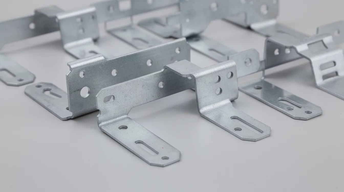
Features cut into the flat pattern before bending interact with material flow at the bend area. Holes near the bend line stretch into ovals. Slots skew. Countersinks lose depth accuracy. These problems are predictable and avoidable with clearance rules.
-
Hole centers: keep at least 2T from part edges and at least 2.5 times the sheet thickness from bends. For 2 mm steel, that means ≥ 5 mm from the bend line.
-
Slots: edges ≥ 4T from bend lines to avoid distortion.
-
Tabs and notches: distance from bend ≥ 3T + bend radius. Tabs should be spaced at least T apart or 1 mm, whichever is greater.
-
Countersinks and threaded holes need more clearance: roughly 3T from bends and 4T from edges for standard thickness ranges.
-
Hardware insertion points (PEM nuts, standoffs) should also follow these spacing rules so that press-fit features remain round and seated after forming.
Following these rules maintains hole roundness, protects mounting points, and preserves functional features. Anebon can adjust flat pattern geometries slightly, with customer approval, to preserve critical hole locations after bending.
Design Rules for Part Layout: Grain Direction, Uniform Thickness, and Chamfers
Sheet metal arrives from the mill with a rolling direction, or “grain.” Bending parallel to the bend line along the grain increases cracking risk, particularly in aluminum 5xxx/6xxx series, high-strength steel, and titanium. Bending across the grain is the safer default. Anebon’s engineers review customer designs for grain direction issues; when customers provide only a 3D model without specifying rolling direction, Anebon assumes the most conservative case. For more on how grain orientation affects bend strength, see Anebon’s grain direction guide.
Sheet metal parts should maintain uniform wall thickness. Uniform wall thickness typically ranges from 0.2 mm to 3 mm for most bent components. Rather than stepping thickness for local stiffness, design the desired shape using flanges, ribs, or hems on a single-gauge sheet. Teardrop hems and open hems both improve edge stiffness and safety; each has minimum radii and return length rules tied to thickness.
Chamfered edges near bends help avoid interference during forming, reduce sharp corners that could crack under tight radius conditions, and improve handling safety. The flat surface at flange edges benefits from a small chamfer (≈ T or less) when the bend creates complex geometries at corners.
Common Bending Defects, Collisions, and How Anebon Mitigates Them
Press brake forming introduces several failure modes. Catching them after cutting wastes material and extends lead times. Catching them before cutting, through simulation and DFM review, costs nothing but time.
-
Insufficient flange support on the die causes the part to twist or compress unevenly, producing angle variation across the bend.
-
Brake collisions occur when part geometry, minimum flange length violations, or successive bends cause the punch to hit a previously formed flange or the machine frame. A part that looks correct in CAD may be impossible to form in the same direction without reordering the bend sequence.
-
Self-collision and lack of gauging surfaces disrupt accurate positioning. Without a flat surface for the back-gauge to reference, bend line location varies from part to part.
-
Feature distortion: holes or slots placed inside the 2.5T zone from the bend line stretch or become oval, losing the inside diameter tolerance needed for fasteners.
Anebon uses offline bend simulation, CNC back-gauges, and experienced tooling selection to detect and resolve these issues before material is cut. For complex OEM housings, Anebon may propose minor changes: adding small tabs, adjusting bend order, resizing reliefs, or shifting features by fractions of a millimeter.
Material Choices for Bending: Mild Steel, Stainless, Aluminum, and More
Common materials used for sheet metal fabrication include aluminum and stainless steel, but Anebon regularly bends mild steel, copper, brass, and titanium as well.
-
Mild steel is the most forgiving material for bends. It allows inside radii of about 1T, stable K-factor around 0.44, and broad standard tooling compatibility. Mild steel requires 1 ton per meter per mm of thickness in air bending tonnage calculations. For detailed forming guidance, see how to bend metal sheet.
-
Stainless steel combines corrosion resistance with high strength but springs back more than mild steel. Forming stainless steel bends typically needs 1.5T to 2T radii, higher tonnage, and sometimes bottoming to hold angle.
-
Aluminum is highly malleable and corrosion-resistant in soft tempers (3003, 5052). Harder 6061-T6 requires larger bend radii (≥ 2T) and careful grain orientation to prevent cracking.
-
Copper is very malleable and offers excellent conductivity, accepting radii as small as 0.5T in soft tempers.
-
Titanium has a high strength-to-weight ratio and fatigue resistance but demands 2T to 3T radii and sometimes coining or rotary bending to control its pronounced springback.
Anebon advises on material and temper during DFM discussions, balancing strength, corrosion resistance, bendability, and cost for each OEM application. Powder coating and other surface treatments are available as post-bend finishing steps.
How Anebon Supports DFM, Prototyping, and Production for Bent Sheet Metal Parts
Anebon’s services relevant to bending include CNC press brake forming, laser cutting, CNC punching, machining of mating components, and in-house tooling selection and setup. The company holds ISO 9001:2015 and ISO 14001:2015 certifications, providing documented control over bend radii, bend allowances, and forming repeatability across production runs. For a broader view of the company’s capabilities, see the overview of sheet metal fabrication.
Anebon’s DFM feedback covers every rule described in this guide: reviewing bend radius, minimum flange length, material thickness, feature placement, grain direction, and bend relief before cutting metal. This review reduces revisions and lead times, especially for high precision assemblies with complex geometries.
Design engineers can send 3D models and drawings to Anebon for DFM review and quoting. Whether the project calls for a handful of rapid prototypes or full-scale production, Anebon manages the entire manufacturing process from flat pattern through bent part to finished assembly.