Optimal Spindle Speed for Aluminum: Enhance Your Machining Efficiency
Spindle Speed for Aluminum: Practical Guide for CNC Machining
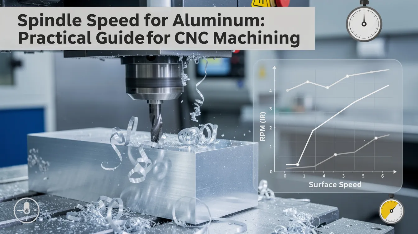
Getting the spindle speed right when machining aluminum is the difference between clean, bright chips flying off the workpiece and a gummy mess welded to your end mill. This post covers the practical rpm values, formulas, and real-world setups you need – whether you run a hobby router or a production VMC.
Quick Answer: Recommended Spindle Speeds for Aluminum
Recommended spindle speeds for machining aluminum are generally high due to the material’s soft nature. For carbide tooling on common wrought alloys like 6061-T6, expect to run between 6,000 and 24,000 RPM depending on tool diameter, alloy, and your machine’s capability. Optimal spindle speed for aluminum with mid-range tooling lands around 16,000 RPM as a useful reference point. Smaller tools require higher RPM to maintain proper cutting speed during machining of aluminum – aim for 10,000+ RPM with tools under ¼ inch.
Here are example combinations for 6061-T6 with carbide end mills:
-
6 mm (¼”) cutter: ~18,000 RPM, feed rate 600–1,000 mm/min, 0.5–1.0 mm depth of cut
-
10 mm (~⅜”) cutter: ~9,500–12,700 RPM, feed rate 2,000–2,500 mm/min for roughing
-
12 mm (½”) cutter: ~6,000–9,000 RPM, feed rate adjusted by flute count and chip load
Optimal spindle speed always ties to cutting speed (surface footage for machining aluminum often ranges from 500 to over 1,000 Surface Feet per Minute) and tool diameter – not rpm alone. Carbide tools on aluminum should run at approximately 300 m/min cutting speed, but your machine rigidity and workholding determine whether you can actually sustain that number. Higher spindle speeds enable faster feed rates during CNC machining of aluminum, which improves productivity and finish quality.
If your spindle is limited – say a bench-top mill capped at 3,000–4,000 RPM – run at your max safe rpm and compensate by increasing feed rate and depth of cut within your machine’s capacity. On the other end, Anebon Metal Products Limited uses industrial spindles rated at 12,000–30,000 RPM on production machines to maintain ideal cutting speeds for small-diameter tools in aluminum.
Key Factors That Control Spindle Speed in Machining Aluminum
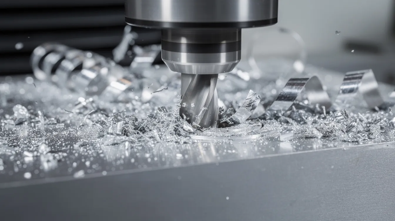
Spindle speed is one variable in a tightly coupled system that also includes feed rate, depth of cut, tool material, alloy type, and machine rigidity. Here are the primary factors affecting your target rpm:
-
Cutting speed and tool diameter mathematically set spindle speed. Aluminum typically prefers higher cutting speeds than mild steel or titanium, pushing rpm upward for any given cutter diameter. Cutting speeds for aluminum typically range around 300 m/min for carbide. Spindle speed affects chip load and cutting efficiency significantly, so getting this relationship right matters.
-
Machine spindle limits often prevent running “ideal” speeds. A manual mill at 4,000 RPM forces compromises on feed and depth of cut, while a high-speed cnc machine reaching 24,000+ RPM opens the full performance envelope. When your spindle is limited, prioritize rigidity and chip load over chasing rpm.
-
Aluminum alloy variation changes everything. Different aluminum alloys exhibit unique hardness and thermal conductivity – 6061 aluminum requires different milling parameters than 1100 aluminum. Harder alloys like 7075-T6 tolerate less aggressive engagement. SFM values for wrought aluminum typically range from 800 to 1,500 SFM. Faster speeds prevent built-up edges on cutting tools, so running too slow on any alloy invites problems.
-
Tool material and geometry determine practical speed ceilings. Carbide end mills are preferred for milling aluminum alloys because carbide tooling allows for much higher RPMs compared to High-Speed Steel tooling. If you use HSS, halve the recommended SFM parameters to avoid heat-related issues. A two flute or single-flute polished O-flute geometry improves chip evacuation at high speeds on routers.
-
Coolant, chip evacuation, and tool stickout govern how aggressively you can push feeds and speeds. Oil, mist, or flood coolant prevents chip welding; shorter stickout improves rigidity. Without good chip clearing, even perfect rpm values lead to chatter and poor results.
Is Spindle Speed the Most Important Parameter for Aluminum?
No. Machine rigidity, work holding, and correct chip load often dominate performance more than spindle speed alone. You can have a faster spindle on a flimsy frame and get worse results than a slower, heavier machine with proper fixturing. Lack of stiffness in the machine causes significant chatter issues that no amount of rpm tuning will fix.
-
Machine rigidity is crucial for preventing chatter during milling. Higher rigidity allows for deeper cuts without vibration, and a rigid machine maintains dimensional accuracy during high-speed machining. Robust machine structures withstand the forces generated during milling – a heavy VMC outperforms a lightweight router at the same rpm every time.
-
Work holding matters equally. A rigid vise, custom fixture, or vacuum table allows higher rpm, deeper depth of cut, and higher feed rate without chatter. If your workpiece moves even slightly, reduce parameters regardless of what charts suggest.
-
Chip load per tooth depends on both spindle speed and feed rate. A high chipload is critical for effective aluminum milling operations – too little feed at high rpm means the tool rubs instead of cutting, destroying tool life and creating heat. Listening to the cut can indicate if the tool is rubbing and whether adjustments are necessary.
-
At Anebon’s production lines in Dongguan, high-speed spindles are paired with rigid 3-axis and 5-axis CNC machines and custom fixtures to exploit optimal chip loads in aluminum across different materials and alloy grades.
-
Priority order for success: 1) secure work holding and rigidity, 2) set correct chip load through proper feeds, 3) then fine-tune spindle speed for surface finish and tool life.
How to Calculate Spindle Speed for Aluminum
Calculating spindle speed starts with two values: your target cutting speed and your tool diameter. For aluminum machining, the spindle speed is calculated based on target SFM and tool diameter. The ideal spindle speed formula involves SFM and tool diameter in inches.
-
Metric formula: RPM = (1,000 × cutting speed in m/min) ÷ (π × tool diameter in mm). Using 300 m/min and a 6 mm carbide end mill: RPM = (1,000 × 300) ÷ (3.14159 × 6) ≈ 15,915 RPM.
-
Imperial formula: The formula for computing RPM is SFM multiplied by 3.82 divided by tool diameter in inches. With a ¼-inch carbide end mill at 1,000 SFM: RPM = (1,000 × 3.82) ÷ 0.25 ≈ 15,280 RPM.
-
Guideline cutting speeds: Aim for 800–1,500 SFM for wrought aluminum alloys during machining. Wrought alloys like 6061 and 7075 typically benefit from higher SFM values of 600 to 1,000 and flood coolant for general milling. Optimal RPM depends on cutter diameter and alloy type.
-
How diameter changes rpm: At a fixed 300 m/min, a 6 mm cutter needs ~15,915 RPM, a 10 mm cutter needs ~9,549 RPM, and a 12 mm cutter needs ~7,958 RPM. The pattern is clear: larger diameter tools run at the low end of rpm while smaller tools push spindle limits.
-
Begin with tool manufacturer data or online cutting speed charts, then adapt values if your spindle cannot reach the calculated rpm. If you are limited, note that reducing speed is acceptable – just adjust feed rate and depth to compensate and save tool life.
Balancing Spindle Speed, Feed Rate, and Depth of Cut
Spindle speed, feed rate, and depth of cut form a triangle – adjust one, and the others must follow. Optimal milling parameters require balancing cutting speed, feed rate, and depth together.
-
Feed rate (mm/min or IPM) equals RPM × chip load per tooth × number of flutes. Example: 10 mm carbide endmill, 3 flutes, 9,500 RPM, 0.08 mm/tooth chip load → feed rate = 9,500 × 3 × 0.08 = 2,280 mm/min. A feed rate of 300 mm/min is effective for 6061 aluminum on lighter hobby setups with smaller tools.
-
Why higher feeds help: Higher feed rates are necessary to prevent chip buildup in aluminum. When the cutter moves fast enough, each tooth takes a real chip instead of rubbing. This avoids built-up edge, reduces heat, and extends tool life. Continuous, curled chips indicate correct feed rates and heat removal during the process.
-
Depth of cut (axial and radial) affects tool deflection and vibration in milling. A common starting rule of thumb: keep initial axial depth at 0.5–1.0× tool diameter, with radial engagement moderated by machine rigidity. Higher spindle speeds improve surface finish when milling aluminum, and spindle speeds above 2,000 RPM improve surface finish in aluminum – but only if depth and feed are balanced.
-
Starting recipes: A ¼-inch two flute carbide end mill slotting 6061 on a hobby router might run at 18,000 RPM, 800 mm/min feed, 0.5 mm axial depth. The same tool on a rigid CNC machining center could push 18,000 RPM, 1,500 mm/min feed, and 1.5 mm axial depth. The machine makes the difference.
-
Anebon’s engineers routinely adjust these three parameters during DFM reviews for OEM customers to balance cycle time, tool life, and surface finish on aluminum parts.
Machine Rigidity, Coolant, and Chip Evacuation
Beyond spindle speed, the physical environment around the cut – rigidity, coolant, chip evacuation – decides how aggressively you can run aluminum. Aluminum needs high spindle speeds up to 10,000+ RPM to avoid tool welding, but that’s only achievable when the machine and setup cooperate.
-
Loose gibs, worn spindle bearings, or a lightweight frame will create chatter long before you reach ideal speeds. High-speed milling requires proper cooling to prevent tool wear, and wrought aluminum requires high surface speeds to effectively evacuate chips from the cutting zone.
-
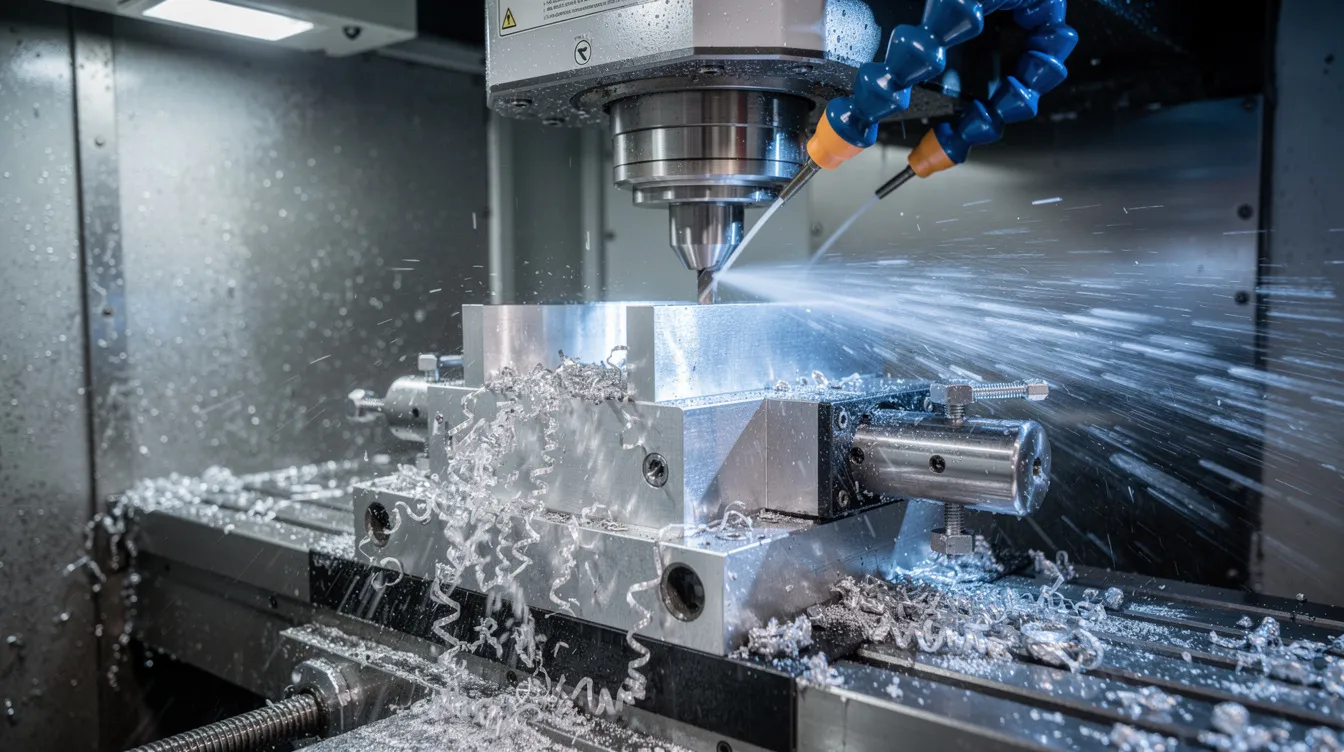
Coolant options: Flood coolant on VMCs is ideal. Mist or spray systems work on smaller CNC routers. Even light oil or WD-40 helps on short hobby jobs. Proper coolant prevents chip welding to the tool at high rpm and carries away heat from the tip of the cutter.
-
Chip evacuation through spiral flute geometry, air blast, and through-spindle coolant keeps slots and pockets clear. Chips packing against the tool cause immediate problems – reduce spindle speed or depth of cut if you see this happening.
-
Note that excessive spindle speeds can cause tool wear and poor finishes on aluminum when the setup can’t handle the load. If you hear chatter or see discolored chips, slow down and check your setup before blaming the speed. Also note that turning operations on a lathe generally require higher SFM values than milling for aluminum.
-
Anebon uses high-pressure coolant and optimized toolpaths on multi-axis CNC machines to maintain stable chip evacuation at elevated spindle speeds in aluminum machining.
Real-World Example Setups for Spindle Speed in Aluminum
Real parameter sets help bridge theory and practice for any machinist or design engineer. Here are three scenarios using different materials, machines, and tools.
Bench-top mill (3,500–4,000 RPM limit): A 10 mm four-flute HSS end mill in 6061-T6. Run at max RPM (~3,800), feed rate ~800–1,200 mm/min, axial depth 1–2 mm, light radial engagement. Expect a slower operation but listen for a smooth, steady cut. Bright, small chips confirm you are not rubbing. This is the low end of what works, but it works if the machine is rigid.
Hobby CNC router (24,000 RPM spindle): A ¼-inch single-flute carbide O-flute in 6061 plate. RPM ~18,000–24,000, feed ~600–1,000 mm/min, axial depth 0.5–1.0 mm. Use mist coolant or air blast. The weight and rigidity of the router frame limits depth more than the spindle does. Watch for chip color – bright silver is good; grey or burnt means too slow or too little feed.
Industrial VMC (Anebon-style production): A 12 mm three-flute carbide end mill with through-coolant in 7075-T6 aluminum. Cutting speed 350–450 m/min, RPM ~9,300–12,000, feed set to 0.08–0.12 mm/tooth, axial depth up to full diameter for roughing with moderate radial width. Chips should be uniform curled strips. Sound should be a consistent, steady hum with no squealing – that’s your confirmation the data is right.
For each setup, the same principle applies: if chips look wrong, the pass sounds wrong, or the finish degrades – adjust one variable at a time until you find the balance.
How Anebon Optimizes Spindle Speed for OEM Aluminum Parts
Anebon Metal Products Limited has served overseas OEMs since 2010, delivering precision CNC machining parts and custom aluminum CNC milling across aerospace, medical, automotive, and electronics industries.
-
Anebon uses CAM software integrated with tool vendor data and in-house process libraries to set initial spindle speed, feed rate, and depth of cut for every new aluminum part. This approach draws on proven cutting parameters for plastics, metals, steel, and aluminum alloys – not guesswork.
-
Process engineers validate speeds via trial cuts, monitoring tool wear under magnification, surface finish (Ra values), and dimensional accuracy down to ±0.002 mm. They create documented parameter sets for each job and adjust based on real-world results.
-
Under ISO 9001:2015 and ISO 14001:2015 certifications, all machining parameters for aluminum components are documented, reviewed, and retained – ensuring repeatability across production runs.
-
For complex geometry on thin walls and deep pockets, Anebon carefully balances spindle speed with toolpath strategies (trochoidal milling, adaptive clearing) to avoid chatter and deflection on lightweight structures.
-
If you need aluminum parts machined to tight tolerances, send your drawings or 3D models for a quote. Anebon can recommend optimal machining parameters – including spindle speed – as part of DFM feedback for your aluminum parts.
Conclusion: Choosing the Right Spindle Speed for Aluminum
The ideal spindle speed for aluminum depends on cutting speed, tool diameter, machine rigidity, and desired chip load – not a single universal RPM. There is no magic number, but there is a reliable process to find the right one for your specific setup.
-
Start from recommended cutting speeds for your alloy, run the calculations for your cutter diameter, then adjust feed rate and depth of cut to match your machine and drilling or milling operation.
-
Continuously monitor sound, vibration, and chip formation when tuning spindle speed for new aluminum jobs. Bright curled chips, steady sound, and clean finish confirm you are in the right range.
-
Engineers and buyers who lack in-house machining support can rely on Anebon to define and control spindle speed and all other parameters for production aluminum components – just reach out with your part files for a fast, detailed quote.