Mastering the Plunging Cutter: Tips and Techniques for Precision Cuts
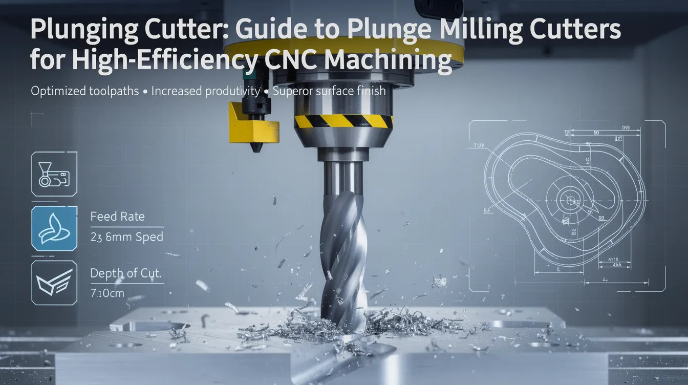
Plunging Cutter: Guide to Plunge Milling Cutters for High‑Efficiency CNC Machining
If you’ve been wondering how to tackle deep pockets, narrow ribs, or heavy roughing without destroying tool life, a plunging cutter might be your best bet. This guide covers everything design engineers and OEM buyers need to know about plunge milling cutters – from mechanics and tool types to practical parameters and real-world applications.
What Is a Plunging Cutter?
A plunging cutter is a tool designed to cut directly into material along the Z-axis of a CNC milling machine. Rather than sweeping sideways through stock like a conventional end mill, it makes a vertical plunge cut into solid material, combining characteristics of both a drill and an end mill for high metal removal in the axial direction.
This is different from a general plunge cut performed with saws or oscillating tools. In CNC metalworking, plunge milling is a dedicated roughing strategy that uses the end of the tool for cutting, allowing the creation of pocket holes and inlay cavities with controlled force distribution. At Anebon Metal Products Limited, we use plunge milling on CNC machining centers and 5‑axis mills for deep cavities and heavy stock removal – situations where conventional side milling struggles with deflection or chatter.
How Plunge Milling Works
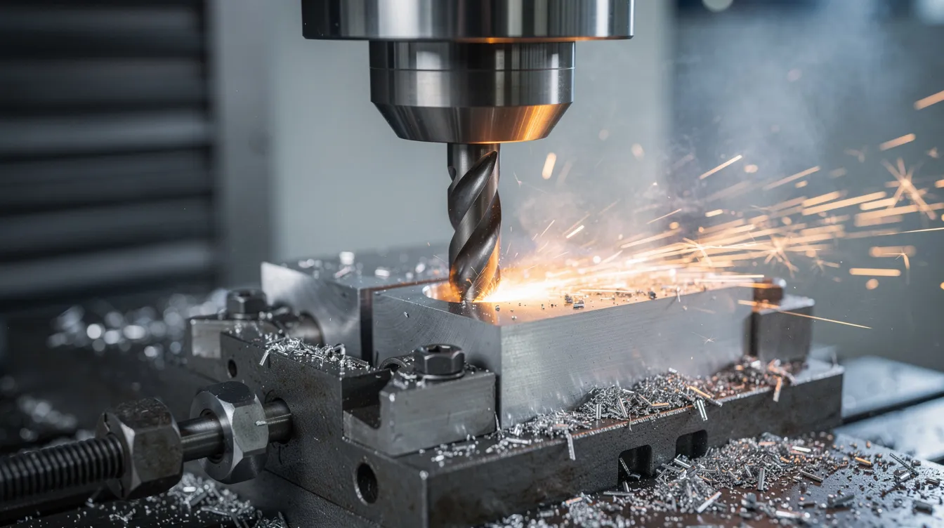
Plunge milling follows a simple process: the cutter makes a vertical entry to a set depth, retracts, steps over a small distance in X/Y, then plunges again. This repeats until the area is roughed out.
The key advantage lies in how plunge cutting changes cutting forces from radial to axial pressure. Instead of side loads pushing the tool sideways (the main cause of deflection and vibration), the load is directed upward into the spindle – the machine’s strongest axis. Plunge cutting minimizes tool deflection by directing forces upward into the spindle, which is why this strategy works so well with long tool overhangs.
Unlike conventional end milling or high-speed machining strategies that rely on radial engagement, plunge milling can be programmed as dedicated plunge cycles in modern CAM systems or approximated via drilling-style toolpaths. The line between a drill cycle and a plunge mill cycle is that the cutter takes a step over between each plunge rather than simply deepening a single hole.
Types of Plunge Milling Cutters
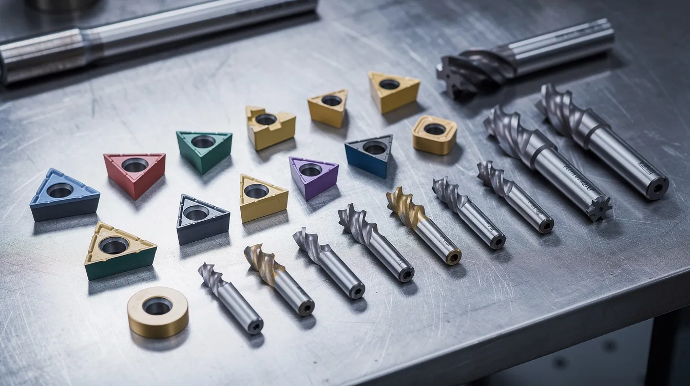
Tool selection depends on the material, depth, required plunge cut geometry, and machine capability. Cutter selection in plunge milling is largely based on diameter and the job at hand.
-
Indexable plunge milling cutters with flat-bottom inserts are designed for heavy roughing in steels and cast irons. Each insert provides multiple cutting edges, and these tools handle large step-overs efficiently. Plunge milling is often used with indexable end mills for this reason.
-
Button cutters (round inserts) are effective for plunge milling due to reduced chatter. The curved geometry distributes cutting forces more gradually, making them a smart choice for difficult alloys.
-
Center-cutting solid carbide end mills handle smaller plunge cuts, tight pockets, and high-precision features. Center-cutting bits are recommended for plunge cutting because they engage cleanly at the tool’s end without wandering.
-
Specialized plunge mills with internal coolant channels address deep cavity roughing where heat management and chip evacuation are critical.
Anebon’s tooling library includes multiple plunge cutter geometries from premium brands to match customer tolerances and materials.
Advantages of Plunge Milling with Plunging Cutters
For OEM production and prototyping, plunge milling delivers a concise list of practical benefits:
-
Greater stability in deep pockets. Because cutting forces act mainly along the spindle axis, plunge milling reduces tool deflection in deep pockets and keeps wall straightness predictable. Plunging reduces vibration in tools with long overhangs.
-
Works on less rigid machines. Plunge milling can reduce chatter in lightweight machines and is suitable when spindle power is limited. Plunge cutters reduce machine power demands compared to traditional milling methods, making them effective on older equipment or mill-turn centers.
-
Higher material removal rates. In titanium pockets, research shows MRR improvements from roughly 760 mm³/min to about 2,200 mm³/min when switching from peripheral milling to plunge milling under constrained overhang. Plunge milling can improve material removal rates in lightweight machines where side milling would cause instability.
-
Extended tool life. Reduced radial load means lower heat concentration, less edge chipping, and more controllable chip evacuation – all of which add value over time.
-
Ideal for roughing 3D features. Plunge milling is efficient for heavy-duty material removal on deep ribs, 90-degree corners, and complex aerospace geometry before finishing passes. Plunge milling can also be used for corner clearing in deep cuts.
Limitations and When Plunge Milling Is Not Ideal
Plunge milling is mainly a roughing strategy and should not be viewed as a complete replacement for all milling approaches.
-
Plunge milling tends to leave scalloped floor and wall surfaces that require semi-finishing and a clean finish pass with ball nose or flat end mills. Surface roughness data shows plunge milling at roughly Rₐ 1.2 µm versus 0.78 µm for face milling.
-
In open, shallow cavities with good machine rigidity, traditional high-speed side milling is often faster and easier to program.
-
Frequent plunges and retracts can increase non-cutting time if toolpaths are not optimized – a real concern on production quantity runs.
-
Some CAM systems offer limited plunge milling support (2D only or no automated retract patterns), requiring manual workarounds to get an effective process.
Key Parameters for Plunge Milling
This section serves as a practical checklist for programmers setting up plunge milling toolpaths:
-
Surface speed: Start conservative, then ramp up based on tool wear and machine feedback. The general rule is to use similar or slightly lower speeds than conventional milling for the same material.
-
Stepover: Recommended stepover for plunge milling is 80% of cutter diameter under favorable conditions. With high overhang or weak rigidity, reduce to around 50–60%.
-
Plunge depth: Set appropriate step-down per plunge based on tool diameter, insert strength, and spindle power. Techniques like programmed partial plunges can aid in chip evacuation in deep blind cavities.
-
Coolant: Use high-pressure coolant delivered through the tool whenever possible, especially on deep features. This is a fact that separates successful plunge milling from problematic runs.
-
Verification: Always verify via CAM simulation. For production jobs, prove the toolpath on a test piece or non-critical part before committing to a full run.
Applications of Plunging Cutters in CNC Production
Plunge milling applications map directly to the parts Anebon manufactures daily:
-
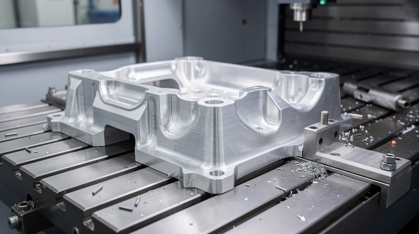
Aerospace housings: Deep pockets in aluminum where long tool reach is unavoidable – plunge milling is effective for deep pockets over four times cutter diameter.
-
Automotive tooling: Roughing thick-section die cast tooling plates where machine rigidity is limited and plunge milling is effective when machine power is limited.
-
Medical fixtures: Machining stainless steel device fixtures where heat and vibration must be tightly controlled.
-
Mold and die surfaces: Plunge roughing 3D surfaces before finishing with ball nose or barrel cutters to achieve the required finish.
Anebon can advise whether plunge milling, traditional roughing, or a hybrid strategy is best for a specific drawing and annual volume.
Plunging Cutters vs. Other Cutting Strategies
Engineers should compare plunge milling with other roughing and drilling strategies before committing:
|
Strategy |
Primary Load |
Best For |
Limitation |
|---|---|---|---|
|
Plunge milling |
Axial |
Deep pockets, long overhang, weak rigidity |
Scalloped surfaces, more retracts |
|
Side/end milling |
Radial |
Shallow area clearing, good finish |
Deflection at long reach |
|
Chain drilling (twist drill) |
Axial |
Hole-based material removal |
Residual material, poor cavity shape |
|
High-feed / trochoidal |
Mixed |
Wide shallow roughing, HSM |
Requires rigid setup, high RPM |
Combining plunge milling for bulk roughing and 5-axis finishing can shorten total machining time on complex parts.
Material Considerations for Plunge Milling
Tool geometry, coatings, and parameters shift depending on workpiece material:
-
Aluminum and non ferrous materials: Allow very high plunge rates with sharp, polished cutters. Coolant is less critical; large step-overs are possible.
-
Steels and cast irons: Prefer robust indexable plunge milling cutters with wear-resistant coatings (AlTiN, PVD). Feed per tooth typically ranges from 0.08–0.20 mm/tooth depending on overhang.
-
Titanium and nickel-based superalloys: Plunge milling is effective when machining superalloys like titanium, but demands conservative stepovers, high rigidity, and optimized coolant delivery.
-
Anebon has deep experience machining stainless steels, titanium, and engineering plastics with tailored plunge strategies across CNC milling services.
Plunge Milling in Anebon’s CNC Machining Workflow
Here’s an inside view of how Anebon applies plunge milling in real projects:
During DFM review, our engineers analyze customer CAD files and flag deep pockets, ribs, or narrow cavities where plunge milling can save time and protect tolerances.
-
CAM programming on 3-axis and 5-axis machining centers combines plunge roughing with finishing toolpaths in a single setup where possible.
-
Process validation via first-article inspection focuses on floor flatness, wall straightness, and tolerance stack-up – the areas where plunge milling reviews matter most.
-
We integrate plunge milling into rapid prototyping through to full production runs while maintaining ISO 9001 quality controls across every part number.
How to Decide if a Plunging Cutter Is Right for Your Part
Use this as a quick decision aid:
-
What is the pocket depth-to-diameter ratio? Plunge milling is advantageous when overall tool stick out exceeds four times diameter.
-
Is your machine rigid enough for side milling at the required reach, or would axial loading be a safer position?
-
Does the part have many deep ribs or narrow cavities? A dedicated plunge milling strategy can cut cycle time and share the workload across more tool life.
-
Want a definitive answer? Share your drawings or STEP files with Anebon for a free manufacturability and plunge milling feasibility review.
Requesting a Quote for Parts Using Plunging Cutters
Anebon serves as a B2B precision manufacturing partner for overseas OEMs on every page of the manufacturing process.
-
Send us 3D CAD files, 2D drawings with tolerances, material specs, annual quantity, and target lead time – add these to your cart of RFQ data.
-
We can propose plunge milling, conventional milling, or hybrid strategies to reduce cost and improve delivery.
-
Highlight deep pockets or challenging features in your design where plunge milling might write a better outcome for cycle time and tool life.
-
Our team will respond with DFM feedback, a suggested process route, and a detailed CNC machining quote. Request your quote here and let Anebon’s engineers find the most effective path from your drawing to a finished part.