Mastering the Lathe: Eight Essential Techniques Revealed
1. Cleverly obtain tiny amounts of food and use trigonometric functions cleverly
Acquire small amounts of food with ingenuity and apply trigonometric functions effectively.During the turning process, workpieces with inner and outer circles requiring high accuracy are frequently processed. Challenges such as cutting heat, friction causing tool wear, and the repeated precision of the square tool holder make it difficult to ensure quality.
To address the precise micro-intake depth, we adjust the longitudinal tool holder at an angle based on the relationship between the opposite sides and the hypotenuse of a triangle, allowing for accurate transverse depth during the turning process. This approach aims to save time and labor, maintain product quality, and enhance work efficiency.
The standard scale value of the C620 lathe tool holder is 0.05mm per division. To achieve a lateral depth of 0.005mm, referencing the sine trigonometric function table:sinα=0.005/0.05=0.1 α=5º44′Therefore, adjusting the tool holder to 5º44′ enables the turning tool to achieve a minimum depth of 0.005mm in the transverse direction with each longitudinal frame movement.
2. Three cases of reverse driving technology
Extensive production experience has demonstrated that employing reverse cutting technology in certain turning processes can yield positive outcomes. Present instances include:
(1) Martensitic stainless steel parts are used as the material for reverse cutting threads.
When working on threaded workpieces with pitches of 1.25 and 1.75mm, it is common to encounter issues related to tool retraction and buckling. Ordinary lathes often lack a dedicated buckling disk device, necessitating time-consuming custom solutions. As a result, processing threads with these specific pitches can be time-intensive and low-speed turning may be the only viable method.
However, cutting at low speed can lead to tool biting and poor surface roughness, particularly when dealing with martensitic stainless steel materials like 1Crl3 and 2 Crl3.To address these challenges, the “three reverses” cutting method was developed in machining practice.
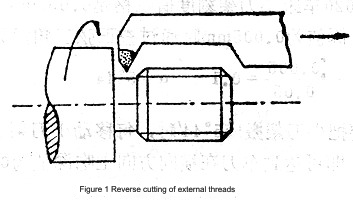
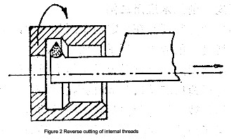
This approach, which involves reverse tool loading, reverse cutting, and opposite cutting directions, has proven to be effective in achieving high-speed thread cutting with smooth tool retraction. This method is particularly beneficial as it allows for efficient cutting and avoids the potential tool gnawing issues associated with low-speed turning.
When the outside of the car, grind a handle similar to the inner thread car knife (Figure 1);
When the inner thread of the car is grinded, a reverse inner threaded knife (Figure 2).
Before beginning the process, adjust the counter-rotating friction disc spindle slightly to ensure the rotation speed when initiating the counter-rotation. Next, position and secure the thread cutter, initiate forward rotation at a low speed, and move to the empty tool groove. Then, proceed to insert the thread turning tool to the suitable cutting depth before switching to reverse rotation. During this phase, the turning tool should rotate from left to right at a high speed. After several cuts following this method, it is possible to achieve a thread with excellent surface roughness and high precision.
(2) Anti -car roll flowers
When using the traditional rolling lathe, it is common for iron particles and debris to enter the workpiece and cutting tool. Employing a new operational technique with the lathe spindle can effectively mitigate the issues encountered during traditional operation and lead to favorable overall outcomes.
(3) Reverse turning of internal and external tapered pipe threads
When working on internal and external tapered pipe threads with low precision requirements and in small batches, you can directly utilize the new method of reverse cutting and reverse tool installation without the need for a template device, maintaining continuous cutting processes.
The efficacy of the manual lateral swiping knife, which sweeps from left to right when turning the external taper pipe thread, lies in its ability to effectively control the depth of the slicing knife from the larger diameter to the smaller diameter due to pre-pressure during the slicing process. The application of this new reverse operation technology in turning continues to grow and can be flexibly adapted to diverse specific situations.
3. New operation and tool innovation of drilling small holes
During turning operations, when drilling holes smaller than 0.6mm, the limited diameter and poor rigidity of the drill bit prevent an increase in cutting speed. The workpiece material, heat-resistant alloy and stainless steel, exhibits high cutting resistance. As a result, using the mechanical transmission feeding method during drilling can easily break the drill bit. A simple and effective solution is to employ a manual feeding method and a specialized tool.
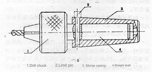
The initial step involves modifying the original drill chuck into a straight-shank floating type. By clamping the small drill bit onto the floating drill chuck, smooth drilling is achieved. The rear part of the drill bit incorporates a straight handle and sliding fit, allowing for free movement within the puller. Meanwhile, when drilling a small hole, gentle manual micro-feeding with the hand-held drill chuck facilitates quick drilling, maintaining quality and prolonging the service life of small drill bits.
Additionally, the modified multi-purpose drill chuck can be utilized for small-diameter internal thread tapping, reaming, and similar operations. For larger holes, inserting a limit pin between the puller sleeve and the straight handle is advised. Refer to Figure 3 for visual details.
4. Shockproof for deep hole processing
During deep hole processing, the combination of a small hole diameter and a slender boring tool shank can lead to inevitable vibration when turning parts with a hole diameter ranging from Φ30 to Φ50mm and a depth of approximately 1000mm. To mitigate the vibration and ensure high-quality deep hole processing, a straightforward and effective approach involves attaching two supports, constructed from materials such as cloth and bakelite, to the rod body.
These supports should match the size of the hole diameter precisely. By utilizing the bakelite block sandwiched with cloth as a positioning support during the cutting process, the tool bar is stabilized, significantly reducing the likelihood of vibration and enabling the production of high-quality deep hole parts.
5. Prevention of breakage of small center drills
In the process of turning, drilling a center hole smaller than Φ1.5mm poses a high risk of breaking the center drill. An effective method to prevent breakage is to avoid locking the tailstock while drilling the center hole. This allows the dead weight of the tailstock and the friction force between it and the machine tool bed to be utilized for drilling. In situations where cutting resistance is excessive, the tailstock will automatically retract, thereby protecting the center drill.
6. Difficulty processing material application
When we have difficulty processing materials such as high -temperature alloy and quenching steel, the surface roughness of the workpiece is required to be in RA0.20 to 0.05 μm, and the size accuracy is also high. Finally, fine processing is usually carried out on the grinding bed.
7. Quick loading and unloading spindle
During turning processes, we frequently come across a variety of bearing kits featuring finely turned outer circles and inverted guide taper angles. Due to their large batch size, they require loading and unloading throughout processing. The time required for tool change is longer than the actual cutting time, leading to reduced production efficiency.
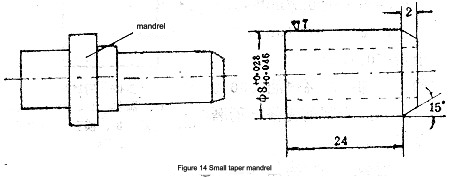
The quick loading and unloading mandrel, along with the single-blade multi-blade (tungsten carbide) turning tool described below, can minimize the auxiliary time and ensure the quality of products when processing various bearing sleeve parts. The production method is as follows: To create a simple small-taper mandrel, a slight taper of 0.02mm is used at the rear.
Once the bearing is installed, the parts are secured onto the mandrel through friction, and then a single-blade multi-edged turning tool is employed to work on the surface. After rounding, the cone angle is inverted to 15°, at which point a wrench is used to swiftly and efficiently eject the parts, as shown in Figure 14.
8. The driving of quenching steel parts
(1) One of the key examples of quenching cnc machined products
①The high -speed steel W18CR4V restructuring and regeneration (repair after break)
② Homemade Non -Standard Slocculus Standards (Hard Extinction)
③ The driving of hardware and spraying parts
④ Driven of hardware light faces
⑤ Refined threaded light tap with high -speed steel knife
When dealing with the hardened hardware and various challenging-to-machine material parts in our production, the careful selection of appropriate tool materials and cutting quantities, as well as tool geometric angles and operating methods, can yield significant economic benefits. For instance, when a square-mouth broach breaks and is regenerated for use in the production of another square-mouth broach, it not only prolongs the manufacturing cycle but also leads to high costs.
Our approach involves using carbide YM052 and other blade tips to refine the broken root of the original broach into a negative front angle r. = -6°~ -8°, allowing the cutting edge to be restored after meticulous grinding with a whetstone. The cutting speed is set at V = 10~15m/min. After turning the outer circle, an empty groove is cut, and then the thread is turned (comprising rough and fine turning). Following rough turning, the tool must be sharpened and ground before completing the external thread, and afterwards, a section of internal thread is prepared to connect the tie rod, which is then trimmed after the connection. As a result of these turning processes, a broken and discarded square broach was repaired and restored to its original condition.
(2) Selection of tool materials for machining hardened hardware
①New grades of carbide inserts like YM052, YM053, and YT05 are typically used at cutting speeds below 18m/min, achieving a workpiece surface roughness of Ra1.6~0.80μm.
②The FD cubic boron nitride tool is capable of processing a range of quenched steel and spray-coated parts at cutting speeds of up to 100m/min, resulting in a surface roughness of Ra0.80~0.20μm. The DCS-F composite cubic boron nitride tool from the state-owned Capital Machinery Factory and Guizhou No. 6 Grinding Wheel Factory shares this performance. While its processing effect is not as superior as cemented carbide, it lacks the same strength and depth of penetration, and comes at a higher cost and with a risk of cutter head damage if used improperly.
③Ceramic cutting tools operate at cutting speeds of 40-60m/min but have poorer strength.Each of these tools presents unique characteristics for machining quenched parts and should be chosen based on specific conditions including material and hardness variations.
(3) Tool Performance Requirements for Different Materials of Quenched Steel PartsQuenched steel parts of varying materials demand distinct tool performance under the same hardness and can be classified into the following three categories:
High alloy steel: This pertains to tool steel and die steel (primarily various high-speed steels) with a total alloying element content exceeding 10%.
Alloy steel: This encompasses tool steel and die steel with an alloy element content ranging from 2 to 9%, for example, 9SiCr, CrWMn, and high-strength alloy structural steel.
Carbon steel: This includes various carbon tool steels and carburized steels such as T8, T10, No. 15 steel or No. 20 steel carburized steel, among others.Following quenching, the microstructure of carbon steel comprises tempered martensite and a small quantity of carbides. This results in a hardness range of HV800~1000, which is higher than that of WC and TiC in cemented carbide and A12D3 in ceramic tools.
Additionally, its hot hardness is lower than that of martensite without alloy elements, generally not exceeding 200°C.
Increasing the presence of alloying elements in steel leads to a corresponding increase in the carbide content of the steel after quenching and tempering, resulting in a complex mix of carbide types. High-speed steel serves as an illustration, where the carbide content in the microstructure after quenching and tempering can reach 10-15% (volume ratio). This includes various types of carbides such as MC, M2C, M6, M3, 2C, and others, with VC exhibiting high hardness (HV2800), far exceeding the hardness of typical tool materials.
Furthermore, the hot hardness of martensite containing numerous alloying elements can be raised to approximately 600°C. Consequently, the machinability of quenched steel with similar macro hardness varies significantly. Before machining a quenched steel part, it is crucial to first analyze its category, understand its characteristics, and select suitable tool materials, cutting parameters, and tool geometry. With proper considerations, the turning of hardened steel parts can be accomplished at various angles.
Anebon is proud from the higher client fulfillment and wide acceptance due to Anebon’s persistent pursuit of high quality both on product and service for CE Certificate Customized High Quality Computer Components CNC Parts Milling Metal, Anebon has been keeping chasing WIN-WIN scenario with our consumers. Anebon warmly welcome clientele from all around the entire world coming in excess of for a visit and setting up long lasting romantic relationship.
CE Certificate China cnc machined aluminium components, CNC Turned Parts and cnc lathe parts. All the employees in factory, store, and office of Anebon are struggling for one common goal to provide better quality and service. Real business is to get win-win situation. We would like to provide more support for customers. Welcome all nice buyers to communicate details of our products and solutions with us!
If you wanna know more or have inquiries, please contact info@anebon.com.


