Mastering the Bending of Metal: Techniques and Tips for Success
Bending of Metal: Practical Guide to Sheet Metal Bending for OEM Parts
Introduction to Metal Bending
Metal bending is a foundational fabrication process used to deform metal into desired shapes by applying force. For OEM manufacturers, it’s the go-to method for creating brackets, enclosures, chassis, medical device housings, and robotic frames from flat stock. Metal bending is used across many industries including construction, automotive, and aerospace, and its versatility makes it indispensable for turning 2D sheet into functional 3D components.
The bending process reshapes sheet metal without removing material, preserving strength while minimizing waste. In a typical manufacturing process, flat blanks are first cut via laser cutting or CNC punching, then formed on a press brake to achieve the desired shape. Because bending is a cold bending process-performed at room temperature-it relies on exceeding the material’s yield point to create permanent deformation rather than on heat or material removal.
Getting the bend radius, bend allowance, and bending method right matters for both function and cost. An undersized radius cracks material. Wrong bend allowances produce parts that don’t fit assemblies. Poor method selection inflates tonnage requirements or cycle times. These are the details that separate a first-pass success from a costly redesign. Anebon Metal Products Limited has provided CNC sheet metal bending from rapid prototypes to full production since 2010, operating from Dongguan, China with ISO 9001:2015 and ISO 14001:2015 certifications.
What Is Sheet Metal Bending?
Sheet metal bending is the process of cold forming flat sheet or plate into permanent angles, curves, or flanges. When force is applied to a metal sheet-typically through a punch pressing into a die-the material first deforms elastically. Once the applied stress exceeds the material yield strength, the deformation becomes plastic deformation, and the bend becomes permanent. After unloading, some elastic recovery (springback) occurs, but the angular shape is retained.
Common bend forms found in OEM parts include:
-
L-bends (90°): The most common single-angle bend for flanges and brackets
-
Z-bends: Offset shapes used for panel overlaps and stepped features
-
Channels and U-bends: Box-like profiles for frames and enclosures
-
Hems: Folded edges for safety, stiffness, or aesthetic finish
-
Joggles: Small offsets for clearance in mating assemblies
Sheet metal is available in gauges from 0.03 mm to 7.62 mm, though precision press brake work typically handles thicknesses from about 0.5 mm to 6 mm for materials like mild steel, stainless steel, and aluminum. Bending can be performed on materials up to 20 mm thick when higher-tonnage bending equipment is available, though tooling and machine requirements increase significantly. If you’re new to the process, our guide on how to bend sheet metal covers the fundamentals in more detail.
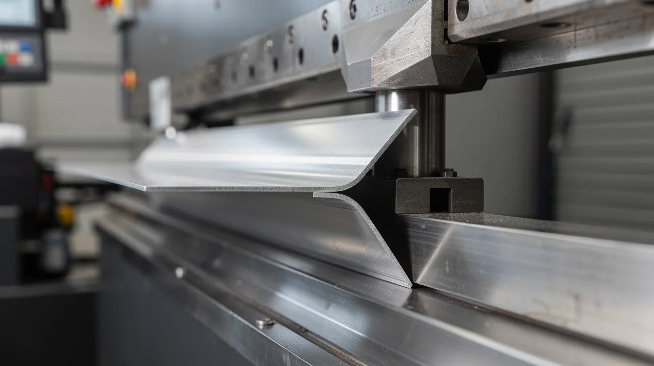
Key Parameters in Metal Bending
Successful bending depends on factors such as material type, thickness, bend radius, and grain direction. Before creating flat patterns or placing a production order, every engineer should understand the parameters that control the outcome.
Inside bend radius is the distance from the center of the bend to the inner surface. The inside bend radius is dictated by punch tip radius, die opening, and material properties such as type and thickness play a significant role in the bending process. Outside radius is simply inside radius plus material thickness.
Bend angle is the interior angle after forming. If the drawing calls for 90°, the punch must overbend slightly to account for springback and achieve the desired bend angle.
Leg length and flange length are the flat portions extending from each side of the bend. These must be long enough for the bottom die shoulders to grip the part.
Bend line is the straight axis along which the bend occurs. Features like holes and slots must maintain adequate distance from this bending line to avoid distortion.
For the bend radius, a common rule of thumb is that the minimum bend radius should be at least equal to the sheet thickness to prevent fractures. Mild steel is the most commonly used bending material and generally tolerates tighter radii than harder alloys. Thicker materials require greater force to bend and limit bending options, often requiring larger bend radii.
Bend allowance, bend deduction, and K-factor form the basis for accurate flat pattern development in CAD and CAM. These values account for how much material stretches and shifts during forming (covered in detail below).
Grain direction-the rolling direction of the metal sheet from the mill-affects ductility and cracking risk. Material grain direction affects bending outcomes significantly, and Anebon’s DFM review checks these parameters on customer drawings or 3D models before production begins.
Common Metal Bending Methods
There are several bending methods available, each balancing accuracy, tonnage, tooling cost, and flexibility. The process uses a punch and a die to apply pressure in metal bending, and the method chosen determines how those tools interact with the workpiece. Simple, linear bends are best handled by a press brake while complex shapes may require specialized bending tools.
For thin sheet metal, v bending on a press brake-including air bending and bottom bending-covers most industrial needs. Bending methods can accommodate material thicknesses from 0.5 mm to 20 mm depending on the technique. Here’s a breakdown of the primary methods used in precision metal fabrication.
Air Bending and V Bending
Air bending is the most common bending method in sheet metal fabrication. The punch presses the metal sheet into a V-die but does not contact the bottom die surface. Only three contact points exist: the punch tip and the two die shoulders. This is sometimes called three point bending, and it achieves angles with 0.25 degree precision when performed on modern CNC bending machines.
Air bending accounts for around 90% of all bending jobs for good reason:
-
Flexibility: Varying bend angles are achievable with a single V-die simply by adjusting punch stroke depth
-
Lower tonnage: Requires less bending force than bottom bending or coining
-
Cost efficiency: Fewer tool shape changes needed, reducing setup time
-
Adaptability: Works well for medium-precision bends, small production runs, and parts where minor angle adjustments are acceptable
The bend radius in air bending is governed by die opening width. For mild steel, inside radius is approximately 0.16–0.20 × V-die width. So a 20 mm die opening would produce an inside bend radius of roughly 3.2–4.0 mm. This must be considered when specifying the desired bend radius on drawings. For more on which tool is used to bend sheet metal, including die and punch selection, see our dedicated guide.
Bottom Bending (Bottoming)
Bottom bending-also called bottoming-is a form of die bending where the sheet is pressed firmly into the V opening so the material conforms closely to the angle of the bottom tool and die walls. Unlike air bending, the part contacts the full die profile.
Advantages:
-
Better angle accuracy and repeatability
-
Bottom bending reduces springback compared to air bending methods
-
Consistent results for parts that must assemble without shimming or post-adjustment
Drawbacks:
-
Bottom bending requires more machine pressure than air bending (roughly 3–5× the tonnage)
-
Requires dedicated punch and die sets matched to specific angles and material thickness values
Bottom bending is the preferred bending operation for OEM parts requiring tight tolerances on angular shape or critical hole alignment near the bend. When your part must hit precise angles across every unit in a production run, the added tonnage and tooling investment is justified.
Coining
Coining takes press brake forming to its extreme. The punch penetrates into the material at the bend, permanently thinning and “stamping” the desired bend angle directly into the sheet. The bending force required is roughly 5–10× that of air bending under similar conditions, as detailed in our forming force analysis.
Coining provides high precision with no springback, making it suitable for:
-
Very tight tolerance work where even 0.5° of springback is unacceptable
-
Producing very small inside bend radii with precise tooling
-
High-strength materials that resist forming by other methods
The trade-off is cost: extreme forces mean greater tooling wear, higher machine requirements, and potential surface marking. Anebon can advise whether coining is appropriate compared to precision air or bottom bending for a specific project based on tolerance requirements and production volume.
Other Practical Bending Methods
Beyond V bending and coining, several specialty methods serve specific geometric needs:
U bending uses a U-shaped punch and die to form channels in a single stroke. Channel width, depth, and wall parallelism can be tightly controlled, making it ideal for structural components like frames and enclosure profiles.
Step (bump) bending approximates large-radius curves by performing a series of small V bends incrementally along the workpiece. This technique is useful for guards, covers, funnels, and other curved forms when dedicated rolling machines aren’t available.
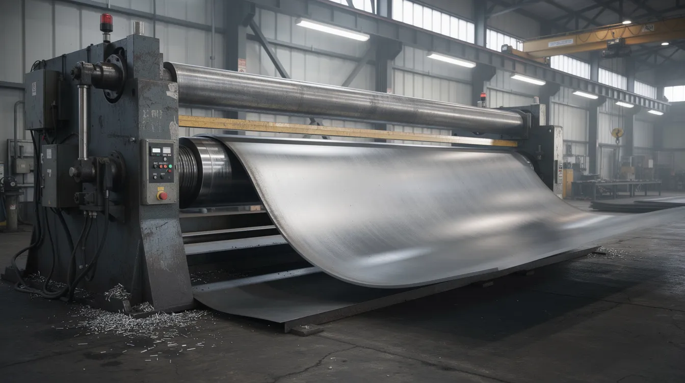
Roll bending uses three-roller machines to produce long, smooth curves and cylinders. Roll bending is used for forming curves, rolls, or cylinders in sheet metal and is common for tanks, large housings, and architectural elements. Rolling can bend materials from 1 mm to over 50 mm thick. For more on creating cylindrical forms, see our guide on how to bend sheet metal into a circle.
Rotary bending and wipe bending are specialty methods for edge flanges or cosmetic surfaces. Rotary bending can produce angles greater than 90 degrees, and both methods help when visible faces must remain mark-free, since bending can leave indentations or scratches on materials if conventional tooling contacts the surface.
Design Rules: Bend Radius, Bend Allowance, and Hole Distance
This section gives actionable rules for engineers creating sheet metal drawings destined for CNC press brake fabrication. Coordinating bend radius, minimum flange length, and hole distance from bend lines prevents cracking, distortion, and tooling interference-the three most common sources of scrap.
Consider a simple example: a 1.5 mm mild steel bracket with a 90° bend. If the inside radius is specified at 0.5 mm (well below material thickness), the outer fibers of the bend will likely crack. Choosing a radius that is too small can cause cracking, surface defects, and reduced fatigue strength. If a hole is placed 1.0 mm from the bending line, it will ovalize during forming. These are preventable errors, and Anebon’s engineering team can suggest optimized dimensions when customer designs don’t follow standard guidelines.
Rule of Thumb for Minimum Bend Radius
The inner radius of the bend should generally be at least equal to the material thickness to prevent fracturing. Here are practical minimums by material:
|
Material |
Minimum Inside Radius (Across Grain) |
Notes |
|---|---|---|
|
Cold rolled steel |
1× material thickness |
Most forgiving; mild steel bends easily |
|
Aluminum 3003, 5052 |
1× thickness |
Aluminum alloys can be bent to tight radii without cracking |
|
Stainless steel 304 |
1.5–2× thickness |
Harder; work-hardens quickly |
|
High-strength aluminum (6061-T6) |
2–3× thickness |
Temper significantly limits ductility |
|
High-strength steel |
2–3× thickness |
Thicker materials may require larger bend radii |
When bending with the grain rather than across it, increase these minimums by 50–100%. CAD default radii should always be checked against the material datasheets and press brake tooling actually available. For a deeper walkthrough, see our article on how to bend sheet metal with a radius.
Standardize on a small set of radii across your project to reduce tooling changes and setup cost. Two or three standard radii are far cheaper to produce than seven unique values.
Calculating Bend Allowance and Bend Deduction
When you bend metal, the outer surface stretches while the inner surface compresses. The neutral axis-where no change in length occurs-shifts inward, and the arc along this axis becomes longer than the original flat line. Accurately calculating bend allowance is essential for correct flat pattern length.
Bend allowance is the length of the arc of the neutral line through the bend zone. It can be calculated using the bend allowance formula:
BA = (π / 180) × (R + K × T) × B
Where:
-
R = inside bend radius
-
K = K-factor (the ratio of neutral line location to material thickness)
-
T = material thickness
-
B = bend angle in degrees
K-factor is typically between 0.3 and 0.5, depending on material, bending method, and tooling. For air bending of mild steel, K ≈ 0.33 is common; for bottom bending, K ≈ 0.42 is typical.
Bend deduction is the difference between flat length and formed length-essentially what you subtract from the sum of flange lengths to determine blank size. Bend allowance is crucial for accurate flat pattern length; getting it wrong by even a fraction of a millimeter compounds across multiple bends into parts that won’t assemble.
Anebon uses CAM software and validated K-factors per material and bending method rather than generic textbook values, significantly improving dimensional accuracy for production runs.
Minimum Flange Length and Hole Distance from Bend
Minimum flange length is the shortest leg that can be bent without the punch contacting the bottom die shoulders or losing clamping stability. Approximate guides:
-
Minimum flange ≈ 4× sheet thickness for narrow die openings
-
Minimum flange ≈ 6× sheet thickness for standard die openings
-
Exact limits depend on the specific tool shape and die width
For hole distance from the bend, keep hole centers at least bend radius + 1.5× material thickness away from the bending line. For slots or large cutouts, increase this clearance further.
Holes and cutouts placed too close to the bend will ovalize, tear, or distort-especially after laser cutting has hardened the cut edge zone. Bending close to an edge should include relief cuts (bend relief) to prevent material tearing. If relocating a hole isn’t feasible, consider increasing the bend radius or adding relief slits at the ends of the bend line.
Material Behavior, Grain Direction, and Springback
The same part geometry behaves very differently in aluminum, stainless steel, and mild steel. Ductility, tensile strength, work hardening rate, and grain structure all determine how a material responds during a bending operation.
In rolled sheet, the material grain follows the elongation direction from the rolling mill. This anisotropy means the sheet bends more easily in one direction than the other. Stainless steel contains at least 10.5% chromium for corrosion resistance, but its higher yield strength and work-hardening tendency make it more demanding to bend than carbon steel. For specific guidance, see our article on how to bend stainless steel sheet metal.
Springback occurs when metal partially returns toward its original shape after the bending load is removed, resulting in a greater bend angle (more open) than intended. This elastic recovery is unavoidable but predictable and controllable.
Grain Direction and Minimum Bend Radius
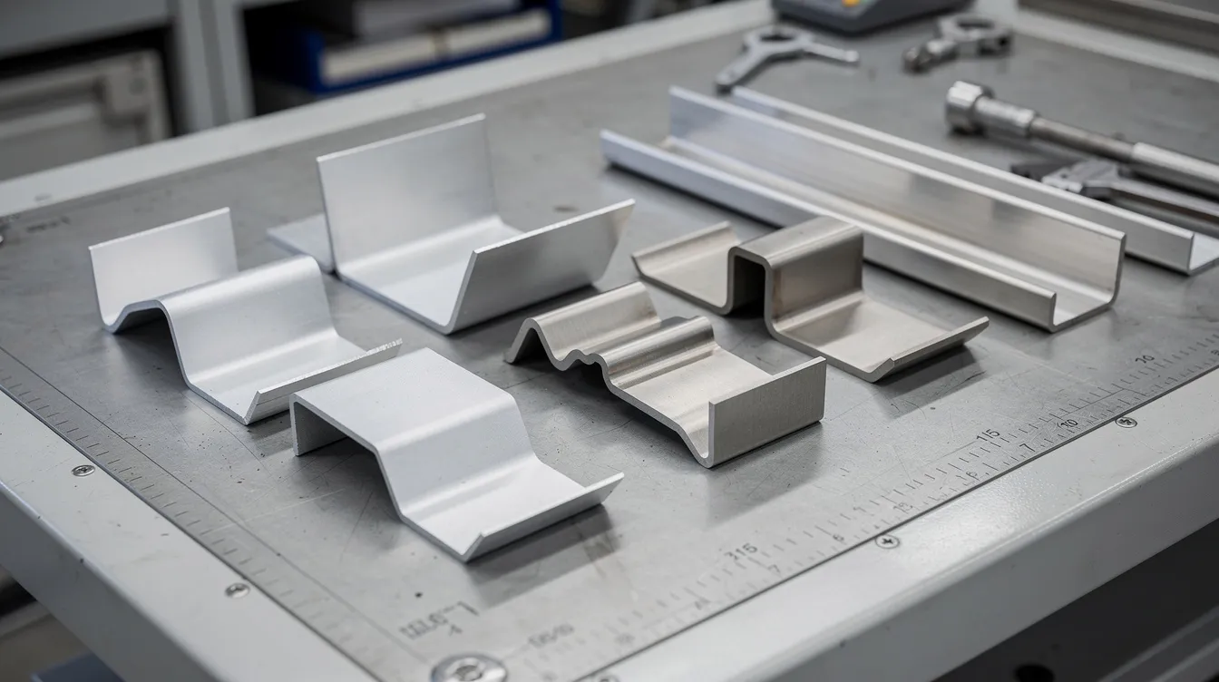
Bending perpendicular to the grain (across the rolling direction) reduces the likelihood of cracking in metals because the grain fibers can stretch along their length rather than fracture across it. Bending should ideally be done perpendicular to the grain direction of the metal to prevent cracking, particularly for tight radii.
When bending with the grain is unavoidable:
-
Increase the inside bend radius beyond minimum recommendations
-
Check the result against material datasheets for the specific alloy and temper
-
Inspect first articles carefully for surface cracking on the outer radius
For high-strength alloys like 7075 aluminum or high-strength steels, grain direction may shift minimum bend radius from 1× thickness to as much as 3–8× thickness. Engineers should explicitly call out grain direction on flat pattern drawings when anisotropic properties affect part performance or fatigue life.
Springback and How to Control It
Springback typically amounts to 1–2 degrees of difference between the angle under load and the final unloaded angle. Springback is influenced by the material’s yield strength and bend radius-higher yield strength and larger bend radii produce more springback. The K-factor helps calculate springback in bending processes alongside other material properties.
Material stress during bending determines springback magnitude. Common compensation strategies include:
-
Overbending by the predicted springback angle (e.g., bending to 88° to achieve 90°)
-
Using bottom bending or coining to plastically deform more of the cross-section
-
Selecting narrower V-dies to increase forming pressure at the bend
-
CNC press brakes with angle sensors that measure the actual angle during forming and adjust stroke in real time
Anebon records empirical springback data for recurring materials and sheet thickness ranges, building validated compensation tables that improve accuracy on future production runs.
Bending Process Workflow at Anebon
Anebon’s typical workflow for sheet metal bending projects follows a structured sequence designed to catch errors early and deliver accurate bending from first article through production:
-
DFM review: Customer CAD files (STEP, IGES) or flat patterns (DXF) are reviewed for bend radii, flange lengths, hole positions, grain direction, and tooling compatibility
-
Laser cutting or CNC punching: Flat blanks are cut with precise edge quality and accurate hole positions
-
Deburring and edge prep: Burrs are removed to prevent crack initiation during bending
-
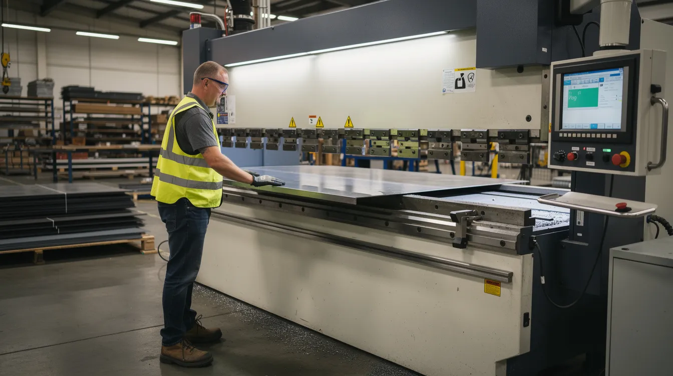
CNC press brake bending: Programs are generated from customer CAD with flat patterns accounting for specific bend allowance values. CNC hydraulic or electric press brakes with programmable backgauges ensure repeatable positioning
-
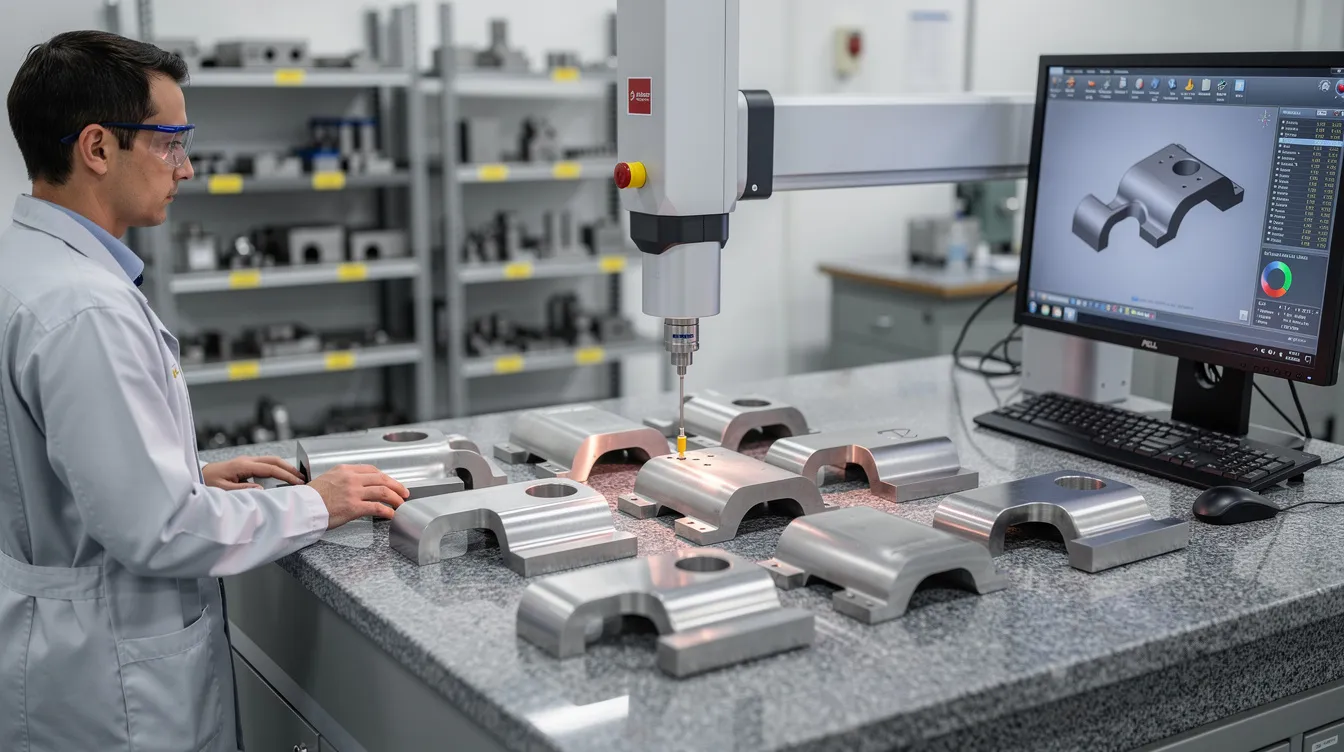
Inspection: First-article inspections using CMM, angle gauges, and height gauges verify dimensions against specification
-
Secondary operations: Tapping, welding, assembly, and surface treatments as required
High-precision applications require CNC-controlled machinery to ensure consistent bending angles and dimension accuracy. Typical achievable tolerances include angles within ±0.5–1.0° and linear dimensions around bends meeting ISO 2768 or tighter customer specifications. Bend angles can achieve 0.25 degrees precision on machines equipped with laser angle measurement systems.
Integration with Laser Cutting and Other Processes
Laser cutting before bending is the standard sequence for precision sheet metal because it provides clean bend edges, accurate hole positions, and consistent flat pattern size. Our laser cutting optimization capabilities pair directly with bending workflows.
When designing parts, consider how laser-cut features relate to bend lines:
-
Holes and slots near bends need adequate clearance (per the rules above)
-
Bend relief cuts should be included in the laser program, not added manually
-
Flat pattern nesting should account for grain direction when specified
Anebon combines laser cutting, CNC punching, and forming into a single production route, minimizing setup changes and lead time. Surface treatments-anodizing, powder coating, plating-are usually performed after bending, so tolerances must factor in coating thickness.
For guidance on optimizing bend order for complex geometries, including parts with multiple bends, see our forming sequence guide.
Design for Manufacturability (DFM) Tips for OEM Engineers
This section provides practical guidance to reduce cost, lead time, and risk of bending defects during new product development and redesign cycles. The goal is to get parts right before tooling is set up.
Start by sending preliminary models to your fabrication partner for DFM review before locking dimensions and tolerances. Common design improvements that consistently reduce cost:
-
Standardize material thickness across product lines to minimize retooling
-
Use consistent bend radii throughout a design-two or three standard values rather than many unique ones
-
Avoid non-essential tight tolerances on non-critical features; let the fabricator apply standard tolerances where function allows
-
Align bends with machine capabilities by confirming available die widths and punch radii early
Include a bending table or notes on your drawings specifying bend radii, grain direction requirements, and tolerances for each bend. This eliminates ambiguity and speeds quoting.
Typical Mistakes in Sheet Metal Bending Design
Too-tight bend radii for the material. Specifying a desired bend radius below the minimum for the alloy and temper leads to cracking on the outer surface. This is especially common with high-strength aluminum and hardened steels where engineers apply mild steel assumptions.
Holes or slots inside or too close to the bend zone. Features within the deformation zone will ovalize, tear, or shift position after forming. This is one of the most frequent causes of assembly fit problems.
Very short flanges. Legs shorter than 4× material thickness often can’t be gripped by the die, resulting in inaccurate bending or tooling interference. If a short flange is unavoidable, discuss with your fabricator-special tooling or staged forming may be possible.
Multiple bends too close together. Adjacent bends can create interference between the part and the press brake tooling. When bends point in conflicting directions or flanges encroach on the machine throat, the part may require multiple setups or redesign. Adjusting part layout or splitting into sub-assemblies sometimes resolves these clearance issues.
Optimizing Parts for CNC Press Brake Production
Design for the brake press by keeping bend lines parallel to at least one reference edge. This enables the CNC backgauge to position the part accurately and repeatably for each bend.
Additional optimization strategies:
-
Use symmetry where possible to reduce operator confusion during setup-but if a part is nearly symmetric, clearly label orientation and bend direction
-
Combine features into a single bent part instead of welding separate brackets when feasible, reducing assembly time and improving accuracy
-
Replace small welded tabs with formed features (bent lances, integral tabs) to eliminate secondary operations
-
Choose standard punch/die combinations (common angles like 30°, 60°, 88°, 90°) to avoid custom tooling costs
Anebon can propose alternative geometries that simplify the manufacturing process while maintaining function-sometimes a small radius change or feature relocation saves significant production cost.
When to Choose Bending vs. Other Fabrication Methods
Metal bending isn’t always the right answer. Here’s how it compares to alternatives:
|
Criteria |
Press Brake Bending |
Stamping/Progressive Die |
CNC Machining / Die Casting |
|---|---|---|---|
|
Volume sweet spot |
Low to medium |
High volume |
Low to high (machining); medium to high (casting) |
|
Tooling cost |
Low-bending requires less tooling compared to other processes |
High (custom dies) |
Low (machining); moderate to high (casting) |
|
Design flexibility |
High-changes are simple |
Low once tooling is made |
Very high (machining) |
|
Material waste |
Minimal |
Moderate (carrier strip) |
High (machining); low (casting) |
|
Part complexity |
2D to moderate 3D |
Simple to moderate 2D |
Complex 3D |
For low to medium production runs, general-purpose v bending using a press brake is cost-effective and fast. Bending is cost-effective for low to medium quantities where the cost of stamping dies can’t be justified. Production volume influences the most economical method for bending-once quantities reach tens of thousands, stamping may become more efficient. However, bending is less cost-effective for high-volume production runs where cycle time per part matters most.
When geometry demands thick sections, internal cavities, or complex 3D features not achievable through sheet forming, machining from solid or die casting may be preferable. Anebon offers CNC machining, die casting, and sheet metal fabrication under one roof, helping customers choose the right process mix for cost and performance.
Bending Capabilities and Quality Assurance at Anebon
Anebon Metal Products Limited provides precision sheet metal bending alongside CNC machining and die casting for OEM customers worldwide. Since 2010, Anebon has served industries from aerospace and medical devices to automotive and robotics, delivering custom precision sheet metal bending parts from rapid prototyping through full-scale production.
Certifications: ISO 9001:2015 and ISO 14001:2015 ensure consistent bending quality and environmental responsibility across all operations.
Materials bent:
-
Aluminum alloys: 5052, 6061, 7075
-
Stainless steels: 304, 316, PH grades
-
Carbon steel and cold rolled steel
-
Copper and brass
-
Selected titanium grades
Measurement and inspection: CMM, height gauges, angle gauges, and documented first-article inspections for new projects. Bending can produce parts with accuracy levels of ±0.05 mm on critical linear dimensions, with angular precision meeting or exceeding customer specifications.
Getting a Sheet Metal Bending Quote from Anebon
To generate an accurate quote quickly, provide the following:
-
3D CAD files (STEP, IGES) or flat patterns (DXF)
-
Material specification and sheet thickness
-
Quantities (prototype, pilot, production volumes)
-
Surface finish requirements (raw, anodized, powder coated, plated)
-
Critical-to-function dimensions and angles with tolerances
Clearly specifying which dimensions are critical and which can accept standard tolerances helps Anebon optimize the bending process for cost without compromising function. Indicate any cosmetic surfaces that must remain mark-free.
Anebon’s engineering team will review your designs for manufacturability-checking bend radius, bend allowance, grain direction, hole distance, and flange lengths-and may suggest improvements that reduce cost or improve part quality.
Whether you’re developing a single prototype bracket or scaling to thousands of structural components, getting the bending parameters right from the start saves time, material, and budget.
Contact Anebon Metal Products Limited today to get a DFM review and quote on your next sheet metal bending project. With integrated CNC machining, die casting, and sheet metal fabrication capabilities, Anebon can support your full range of precision parts needs from a single, certified source.