Mastering the Art of the Metal Bend: Techniques for Precision Bending
Metal Bend: Practical Guide to Sheet Metal Bending for Precision Parts
Introduction to Metal Bending in Modern Manufacturing
Metal bending is one of the most widely used forming operations in precision manufacturing. The process transforms flat sheets of material into three-dimensional parts – automotive brackets, medical device housings, electronics enclosures, HVAC ductwork – while metal bending alters shape without changing volume. Because bending processes often result in minimal material waste and the technique is cost-effective for low to medium quantities, it remains a go-to method for OEM production across industries.
Before diving deeper, here are the core terms you will encounter throughout this main article:
-
Bend radius – the radius of curvature on the inside surface of a bend.
-
Material thickness (T) – the sheet gauge, central to nearly every bending calculation.
-
Bend allowance – the arc length consumed by the bend along the neutral axis.
-
K factor – the ratio locating the neutral axis relative to thickness.
-
Bend deduction – the amount subtracted from flange lengths to derive the flat pattern.
Anebon Metal Products Limited has been providing high precision sheet metal bending and CNC fabrication services since 2010 from its facility in Dongguan, China. As a practical example, consider a telecom enclosure made from 1.5 mm aluminum 5052-H32 with multiple flanges and stiffening ribs – exactly the kind of finished part where accurate bend geometry determines whether the housing seals properly and mates with internal PCBs.
Basics: How Metal Bending Works
When a flat sheet is forced around a punch into a die, the outer fibers of the material stretches under tension while the inner fibers compress. Between these two zones sits the neutral axis – a plane where the material experiences neither tension nor compression. Understanding where this axis falls is the foundation of every flat pattern calculation.
Key parameters that define any bending operation:
-
Bend angle – the included angle between the two flanges (e.g., 90°, 120°). Bend angles are influenced by material thickness and bend allowance.
-
Inside and outside radius – the inside bend radius is measured at the inner wall; the outside radius equals the inside radius plus thickness.
-
Material thickness – drives minimum radius, required force, and tooling selection.
-
Flange length – the distance from the bend line to the free edge; must be long enough for tooling contact.
Most industrial sheet metal bending is performed cold, at room temperature, using press brakes and matched tooling rather than heating. Press brakes are the primary machines used for bending sheet metal, and cold bending can actually strengthen the metal during the process through work hardening in the deformed zone.
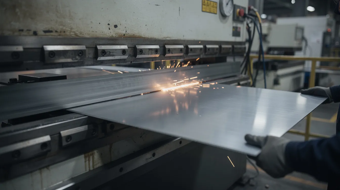
When these fundamentals are well understood, the bent part matches CAD geometry and assembly requirements – reducing rework and scrap.
Different Types of Metal Bending Processes
Choosing the right bending process depends on the part’s tolerance requirements, material, production volume, and geometry. The bending method depends on material type, thickness, required accuracy, and production volume. Below is a comparison of the most common industrial methods, including when Anebon recommends each for OEM projects.
Air Bending
Air bending is a precise method that uses a punch to bend metal without touching the bottom die. The workpiece contacts only the punch tip and the shoulders of the v die, and the bend angle is controlled entirely by stroke depth. This makes air bending extremely flexible – a single tool shape can produce many different angles with the same technique. Typical for 0.5–6 mm sheet metal, it requires significantly less force than other methods. For a 1-meter Z-bend in 2 mm mild steel, air bending needs roughly 15 tons. Anebon recommends air bending for small-to-medium batch OEM parts with moderate angular tolerance (±0.5–1°), such as general enclosures and brackets.
Bottoming
Bottom bending forces the material against the die to create accurate bends with reduced springback. The sheet fully seats on the die sidewalls, producing consistent results across long production runs. Bottoming demands 3–5× the force of air bending – around 75–100 tons for that same 1-meter Z-bend. Anebon recommends bottoming for precision mild steel brackets and mating faces where a fixed 90° bend must hold tight tolerances.
Coining
Coining uses high pressure to create precise bends in metal by plastically deforming the entire cross-section near the bend lines. Springback is virtually eliminated, enabling angular tolerances of ±0.1–0.25°. The trade-off is very high tonnage (5–8× air bending force) and accelerated tooling wear. Anebon recommends coining for aerospace or medical parts where critical fits cannot be adjusted after the bending operation.
Three-Point Bending
Using servo-controlled lower dies and hydraulic cushions, three-point bending achieves 0.25 degree precision by controlling material flow in real time. It suits thicker sheets (above 6 mm) or parts where springback varies across the width. Anebon applies this for heavy structural panels requiring parallel flange surfaces.
Folding / Wiping
Folding is used to create complex box shapes in sheet metal fabrication. Clamps hold the workpiece while a blade wipes the flange upward along a straight axis. Wipe bending clamps the metal while a punch moves across to produce small, accurate bends. This method excels at long, straight flanges on cabinets, doors, and aesthetic panels where surface finish on the outside face matters. Anebon recommends folding for electronics chassis and enclosure panels.
Roll Bending
Rolling machines are used to create curves and cylindrical shapes in metal bending. Rolling passes sheet metal through rollers to create large, smooth curved shapes – full cylinders, cones, or tubes. Rotary draw bending maintains tube cross-section during the bending process, making it ideal for tubular frames. Anebon uses roll bending for cylindrical shells and large-radius enclosures.
V-bending and U-bending are classical methods for bending metal into respective shapes and remain common across all of the above process families.
Key Design Parameters: Radius, K-Factor, Bend Allowance & Bend Deduction
Getting the flat pattern right depends on understanding how the neutral axis shifts and how the material stretches during forming. Errors here cascade into misaligned holes, incorrect flange dimensions, and assembly failures.
Bend Radius
Bend radius is the radius of the bent metal at the punch – specifically, the inside surface curvature. Too small a radius relative to material thickness causes cracking on the outer fibers; too large wastes space and may compromise fit. Practical starting guidelines:
-
Mild steel: inside radius ≈ 1× material thickness
-
Stainless steel 304/316: ≈ 1.5–2× T
-
Aluminum 6061-T6: ≈ 1.5–3× T
For deeper guidance on radius selection, see How To Bend Sheet Metal With A Radius.
K Factor
The k factor is the ratio of the neutral axis distance from the inside surface divided by thickness. K-factor typically ranges from 0.3 to 0.5. For air bending of mild steel, a common value is ~0.44; stainless steel ~0.45; soft aluminum ~0.38–0.42. Tighter bends or coining push the value lower.
Bend Allowance
Bend allowance is the length of the arc of the neutral line – calculated as (π/180) × bend angle × (R + K × T). For example, a 90° bend in 2 mm mild steel with R = 2 mm and K = 0.44 yields BA ≈ 4.7 mm. This value is added between straight segments when creating a flat pattern in CAD.
Bend Deduction
Bend deductions account for material stretching during bending. The bend deduction is the amount subtracted from the sum of outside flange lengths to determine the required flat blank dimension. It relates directly to bend allowance and outside setback, and errors here produce parts that are too long or too short.
Modern CAD/CAM platforms (SolidWorks, Inventor, Creo) automate these calculations – but only if the k factor and tooling data are correct. Anebon validates every new material and tooling combination with trial bends and tolerance stack-up measurements before volume production. Designers should share their bend tables or requested k factor values when requesting a quote.
Material Considerations: Thickness, Grade, and Formability
Material choice directly affects achievable bend radius, minimum flange length, force requirements, and cracking risk. Here is how the most common materials behave:
-
Mild steel (Q235 / A36): Mild steel is favored for its excellent formability and strength. Tolerates inside radii down to 1× T; moderate springback; widely used for brackets, frames, and automotive structural components. Automotive industries commonly use metal bending for body panels and structural components.
-
Stainless steel (304, 316): Stainless steel is known for its corrosion resistance and is often used for kitchen appliances, medical devices, and food-processing equipment. Higher yield strength means greater spring back and the need for larger radii. For detailed stainless bending guidance, see How To Bend Stainless Steel Sheet Metal.
-
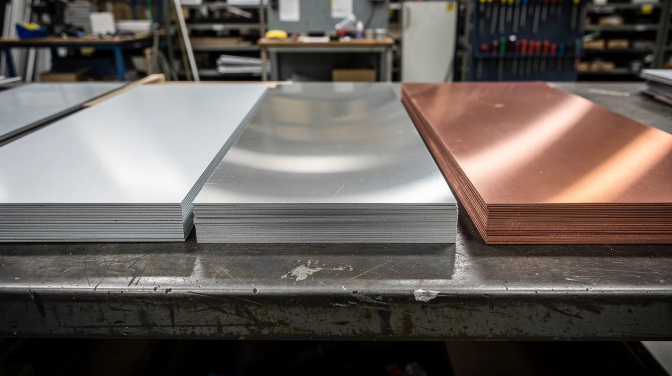
Aluminum alloys: Aluminum is lightweight and highly malleable, and aluminum is commonly used in aerospace and automotive industries. 5052-H32 forms well at 1× T radius; 6061-T6 needs 1.5–3× T or partial annealing for sharp bends. Aerospace industries utilize metal bending for lightweight structural components.
-
Copper: Copper is used in electrical applications due to its conductivity. Excellent ductility allows tight radii with minimal cracking risk.
-
Brass: Brass has low friction properties, suitable for fittings and decorative hardware. Forms easily but watch for surface marking.
HVAC industries use metal bending for ductwork and ventilation components, often in galvanized steel or aluminum.
Thickness effects: Thicker sheet (above 4 mm) demands a larger die opening, larger inside radius, and significantly more tonnage. Thin sheet below 1 mm risks distortion and edge marking, so tooling and support strategy matter – sometimes requiring padded or coated tools.
Real-world example: A 2.0 mm thick 304 stainless enclosure for electrical distribution requires a minimum inside bend radius of 2.0–3.0 mm (1.0–1.5× T) to avoid cracking on visible surfaces. Extreme bending angles can cause deformation in certain metals, especially work-hardened stainless, so the designer should specify temper, thickness, and surface finish requirements on RFQs sent to Anebon.
Minimum Flange Length and Tooling Limits
Flange length is the distance from the bend line to the free edge of the workpiece. It is constrained by die opening width and punch nose radius. If the flange is too short, the material cannot maintain full contact on the die shoulders, leading to slipping, rolling, inconsistent bend angle, and cosmetic defects on the bent part.
A reliable rule of thumb: minimum flange length ≈ 4× material thickness for standard v die air bending. For bottoming or coining, allow 5–6× T. Another approach: minimum flange ≈ half the die opening plus material thickness. For a 25 mm die opening with 1.5 mm thick steel, that means a flange of at least ~14 mm.
Design practices to avoid issues:
-
Keep holes and cutouts at a distance of at least 2.5× T + R from the bend tangent point.
-
Add bend reliefs where flanges intersect to prevent tearing.
-
If a short flange is unavoidable, consider welded tabs or a redesigned multi-bend approach.
Bending requires precise tooling, leading to high upfront costs – but Anebon’s DFM review process can advise on minimum flange lengths for your specific material thickness and die set before production begins.
Consult your bending tooling chart early. It prevents costly redesigns later.
Common Issues in Sheet Metal Bending and How to Avoid Them
Most bending problems trace back to design oversights or incorrect process parameters. Here are the common issues and practical mitigations:
-
Cracking on outer surface: Inside radius too small for the alloy. Increase bend radius or select a softer temper. For hard aluminum, consider local annealing.
-
Excessive springback: Manufacturers need to manage springback compensation during bending processes. High-strength materials or large radii amplify spring back. Use over bent angles, bottoming, or coining where feasible.
-
Distorted holes or slots near bends: Features too close to bend lines become oval or shift. Follow minimum distance guidelines (≥ 2.5× T + R from the tangent point) or add reliefs.
-
Inaccurate finished part dimensions: Incorrect k factor or bend deduction in the flat pattern. Validate against sample parts and update the bend table. Operator skill significantly impacts the success of bending operations, so experienced press brake operators are critical.
-
Surface marking and scratches: Use protective films on flat sheets before pressing, polished tools, or urethane pads for cosmetic panels.
Anebon performs first-article inspection (FAI) using calibrated press brakes and CMM or laser measurement to keep angles within specified tolerances on every production run.
From Flat Pattern to Finished Part at Anebon
Here is how a typical sheet metal bending project flows through Anebon’s facility – from concept to shipped parts:
-
Receive files – 3D model and 2D drawings specifying material thickness, bend notes, angular tolerances, and surface finish.
-
DFM feedback – Review bend radii, minimum flange, hole-to-bend distance, and forming sequence to catch issues before tooling.
-
Process and tooling selection – Choose air bending, bottoming, folding, or other methods based on quantity, tolerance, and material. Match v die opening, punch nose radius, and machine tonnage.
-
Trial parts – Produce sample parts from a single piece of stock. Measure bend angle, flange length, and critical dimension to confirm bend allowance and k factor.
-
Volume production – Ramp up with in-process inspection (angle gauges, CMM, laser) targeting up to ±0.5° bend angle control and tight linear tolerances.
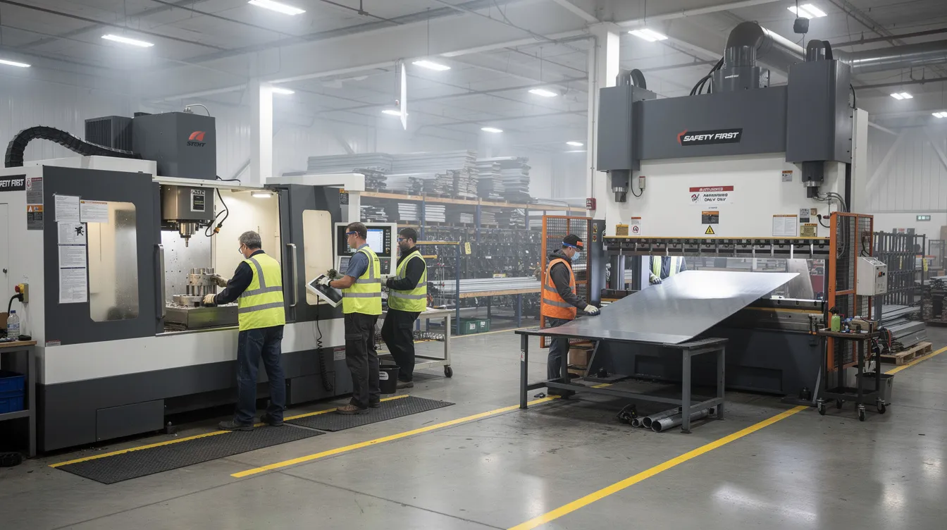
Anebon integrates bending with CNC machining for stiffeners, die casting for mating parts, and surface treatments (anodizing, powder coating) after forming. ISO 9001:2015 certified quality systems ensure consistent results across every lot.
Design Tips to Improve Manufacturability and Cost
Small adjustments to bend design can significantly reduce cost and lead time. Here is a practical checklist:
-
Standardize inside bend radii across a part family to share common tooling and minimize setup time. Fewer tool changes means faster turnaround.
-
Bend perpendicular to grain direction on harder alloys to reduce cracking risk. Align bends with grain only when the part geometry requires it and the alloy permits it.
-
Avoid calling out “sharp” 90° bends. Specify an achievable inside radius based on material and thickness – this prevents the shop from guessing and protects the curve quality of visible surfaces.
-
Consolidate features. Combine multiple components into a single bent part instead of several welded pieces to reduce welding, machining, and assembly costs. This approach can produce lighter, stiffer assemblies.
-
Set realistic tolerances. Overly tight angular or dimensional tolerances on every bend drive up inspection, scrap, and cost without functional benefit.
-
Consider joggling where needed. Joggling creates a step-like offset in metal, often used in aerospace components to allow overlapping skins. Not every shop handles it – discuss with Anebon early.
Involve your bending supplier during the design phase. Anebon’s DFM review on complex enclosures and brackets routinely saves customers a revision cycle.
Frequently Asked Questions About Metal Bending
Below are answers to questions Anebon frequently receives from overseas OEMs and design teams.
What is the difference between air bending and bottoming, and when should each be used? Air bending does not force the sheet into full contact with the die, offering flexibility and lower force. Bottoming seats the sheet fully against the die for tighter angle control. Use air bending for moderate tolerance work and bottoming when angular precision under ±0.5° is required on production parts.
How do I choose the correct bend radius for 1.0 mm, 2.0 mm, and 3.0 mm sheet in mild steel and stainless? For mild steel, start at 1× T (1.0 mm radius for 1.0 mm sheet, etc.). For stainless 304/316, use 1.5–2× T. Always test with a sample bend when the part is cosmetic or structural.
How accurate are bend allowance and bend deduction tables compared to real production parts? Standard tables get you within 0.2–0.5 mm on most parts. Material batch variation and tooling wear can shift values, so Anebon validates tables with first-article measurement and updates them per job.
What is the maximum material thickness Anebon can bend? Anebon handles common steels and aluminum from thin gauge (~0.5 mm) up to approximately 10 mm, depending on alloy and bend geometry. Contact us with your specific form requirements.
How should I dimension my drawing? Specify the inside bend radius and reference critical outside or mating-face dimensions. Avoid mixing inside and outside references on the same drawing to prevent ambiguity at the machines.
Have a specific question? Send your CAD files along with material, thickness, and tolerance requirements for tailored advice.
Partner with Anebon for Precision Metal Bending
Anebon Metal Products Limited delivers precision sheet metal bending, CNC machining, and die casting under one roof – creating a streamlined path from prototype to full production for OEM clients worldwide. Founded in 2010 in Dongguan, Guangdong, China, and certified to ISO 9001:2015 and ISO 14001:2015, Anebon serves aerospace, medical, automotive, electronics, robotics, and industrial customers with tolerances as precise as ±0.002 mm on machined features and consistent bend quality across every run.
Whether you need five prototypes or fifty thousand production parts, request a quote by attaching your 3D models, 2D drawings, and key bending requirements – material thickness, target bend radius, and angular tolerances. Anebon supports projects planned through 2026 and beyond, focused on building long-term OEM partnerships.