Mastering the Art of Creating a Bent Metal Sheet for Your Projects
Bent Metal Sheet: Practical Guide to Bending Sheet Metal for Precision Parts
Introduction to Bent Metal Sheet
A bent metal sheet is a flat piece of metal that has been reshaped along one or more straight lines to form angles, flanges, or channels. Unlike machining or cutting, bending reshapes material instead of cutting it away, which helps reduce waste and makes efficient use of raw stock. This bending process is fundamental across industries: automotive brackets that support engines and dashboards, electronics enclosures where folded edges stiffen thin panels, medical device housings that demand cleanliness and rigidity, and HVAC systems that require folded sheet metal for ducts and ventilation components. Bent metal sheets are a fundamental component in construction and fabrication, and bending creates parts like brackets, panels, and struts that would be far more expensive to produce by other means.
Sheet metal bending is used in automotive and aerospace industries, and common applications extend to roofing, chassis assemblies, and robotics frames. One often-overlooked advantage is that bending techniques can increase the material’s stiffness without adding weight, which is critical in weight-sensitive designs. Bending is also faster than welding and riveting processes, cutting labor costs and cycle time.
Anebon Metal Products Limited has specialized in precision sheet metal bending and CNC fabrication since its founding in 2010 in Dongguan, China. With ISO 9001:2015 and ISO 14001:2015 certifications, Anebon serves overseas OEM clients from rapid prototyping through full production with tight tolerances.
This article answers three questions: how to bend sheet metal correctly using both workshop and industrial methods, what key bending methods (air bending, cold bending, bottoming) exist and when to use each, and how to design bent parts that are easy and economical to manufacture. Whether you need to bend metal for a one-off prototype or create parts at volume, the guidance here will help you get it right.
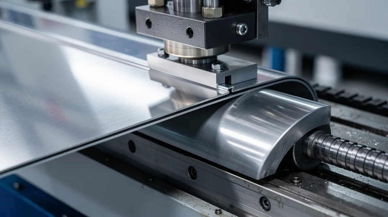
How to Bend Sheet Metal Safely with Common Tools
Not every project requires industrial equipment. If you need to bend sheet metal in a workshop for prototyping or very small runs, here is a practical approach using common tools.
Step 1 – Mark the bend line. Use a scribe, punch, or sharp tool to mark the intended bend line on the sheet. Accuracy here determines the accuracy of the finished bend. If the grain direction is visible on the surface, note it as well.
Step 2 – Set up the “sandwich” fixture. Place two pieces of angle iron (or rigid steel bars) along both sides of the sheet, aligned precisely on the bend line. Clamp the assembly firmly to a workbench, sawhorses, or into a bench vise. This creates a straight fulcrum for a controlled bend. For longer pieces, add intermediate clamps to prevent twisting.
Step 3 – Apply bending force. For mild steel sheet in the 1.0–1.5 mm range, a soft mallet or lever bar can produce a clean 90° bend. Use a soft wood or plastic block between the hammer and the metal to avoid surface damage. For thinner aluminum, less force is needed. Sheet metal bending uses specialized equipment like press brakes for production, but hand tools work for low-volume situations.
Safety practices to follow:
-
Wear cut-resistant gloves and safety glasses – small chips can spall when metal deforms or burrs break off
-
Check clamp tightness before applying any bending force; slipping under load causes inaccurate bends or injury
-
After bending, deburr all sharp edges (inside bend, outside bend, and cut edges) with a file or grinder
-
Release tension slowly to account for springback
Common metals for bending include steel, aluminum, and copper, all of which respond well to this manual approach when gauges are thin. For a deeper dive into workshop techniques, see our guide on how to bend sheet metal without a brake.
Understanding Bend Radius, Bend Allowance, and Bend Deduction
Getting a bent sheet metal part to match your drawing depends on three interrelated values: bend radius, bend allowance, and bend deduction. Ignore any one of them and your flat pattern will be wrong, your flanges too long or too short, and your assembly will not fit.
Bend Radius
The bend radius is the inside radius of the curve after bending. It controls how much the material stretches on the outside and compresses on the inside. If the inside radius is too small relative to material thickness, the outer fibers exceed their tensile limit and the part cracks. Bend radii are often kept at or above sheet thickness to prevent cracking. The bend radius depends on material properties and tooling geometry – for example:
-
1.0 mm aluminum 5052-H32: minimum inside radius ≈ 1.0 mm (1× thickness)
-
2.0 mm cold rolled steel: minimum radius ≈ 1.0–2.0 mm (0.5–1× thickness)
-
Stainless steel 304 above 1.5 mm: radius may need 1.5–2.5× thickness, especially when bending parallel to the grain direction
Bend Allowance
When you bend sheet metal, the material stretches on the outer surface of the bend zone. Bend allowance is the arc length of material consumed in the bend. Designers must account for this stretch to calculate the correct flat-pattern length. The formula is:
BA = (π / 180) × θ × (R + K × T)
where θ is the bend angle, R is the inside bend radius, T is material thickness, and K is the k factor. The k factor estimates material stretch during bending by locating the neutral axis – the plane where no stretching or compression occurs. Typical k factor values range from 0.33 to 0.50, with mild steel around 0.44 and aluminum 5052 around 0.38–0.41. For detailed k factor optimization, see Bending Without Breaking: Optimizing K-Factor Calculations for Tight-Tolerance Sheet Metal Enclosures.
Bend Deduction
Bend deduction is the value subtracted from the sum of your flange lengths to determine the flat blank size. Essentially, BD = (sum of flanges) − flat pattern length. CAD/CAM systems use this value to unfold 3D models into accurate flat patterns. Without correct bend deduction, bent sheet metal parts will be dimensionally off, requiring rework or scrap.
Anebon’s engineering team helps customers pick the right bend radius and k factor for typical OEM materials – mild steel, aluminum 5052, stainless 304/316 – avoiding repeated prototyping and wasted material.
Key Bending Methods: Air Bending, Bottoming, and Cold Bending
Precision fabrication shops choose their bending method based on the tolerances required, the material type, batch size, and cost targets. Each method trades off between tooling expense, tonnage demand, springback risk, and repeatability.
Air Bending
Air bending is the most widely used method on modern brake presses. The punch pushes the sheet partway into a V-die without forcing it to the bottom. Air bending leaves a gap between the material and the die, meaning the bend angle is set by punch depth rather than die geometry. This makes it flexible – the same tooling can produce different angles simply by adjusting stroke depth.
Advantages include lower bending force requirements, reduced tool wear, and faster setup. The trade-off is greater sensitivity to springback variation, which means the material tries to return toward its original shape after the punch retracts. Springback typically amounts to 1–2° after bending in soft materials, though stainless steel can spring back 4–7°. CNC controllers compensate by overbending to hit the desired angle. For more on how to use a sheet metal bender effectively, we cover machine setup in detail.
Bottom Bending and Coining
Bottom bending pushes the sheet deeper into the die so it contacts more of the die surface. This reduces springback and improves angle consistency, but demands higher tonnage and matched die angles. It sits between air bending and coining in terms of cost and precision.
Coining applies very high force – often 5–8× the tonnage of air bending – to plastically deform the material completely around the bend. The result is excellent angle accuracy with almost zero springback, but tooling cost, press capacity, and risk of surface imprinting all increase. Different bending methods include air bending and bottoming, and the right choice depends on part requirements.
Cold Bending
Cold bending refers to any bending performed at room temperature without heating. Most sheet metal bending is cold bending, including air bending, bottoming, and coining when done cold. Bending 304 stainless steel panels and aluminum 5052 housings cold is standard practice. Heat is only introduced for very tight bends in high strength materials or thick plate where cold forming would crack the workpiece.
Modern equipment improves the precision and repeatability of bends, and bending can produce parts from materials up to 20 mm thick. Beyond that, sheet metal bending is limited to materials under 20 mm thick in most press brake operations. Bending can produce parts with accuracy levels of ±0.05 mm when CNC equipment and closed-loop sensors are used, making it an automated process capable of consistent results.
Anebon selects the bending method based on batch size, material, and tolerance needs – air bending for general production, bottoming or coining when the part demands it.
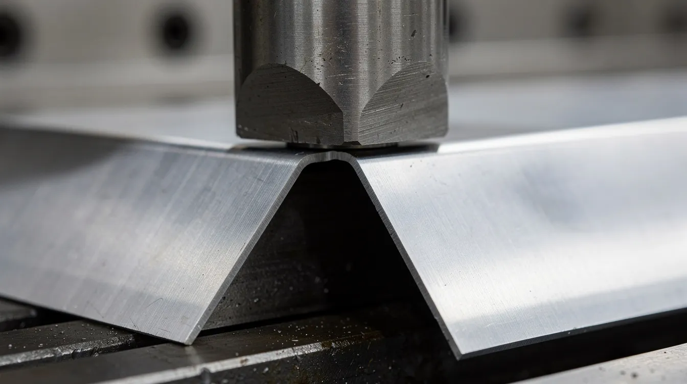
Brake Presses, Grain Direction, and Common Tools Used to Bend Sheet Metal
CNC Brake Presses
A modern CNC press brake uses hydraulic or electric drive, programmable backgauges (X, Y, Z axes), and crowning systems to compensate for machine deflection across long parts. Angle sensors provide closed-loop feedback, adjusting ram depth in real time to account for material variation. Press brakes are commonly used for high-precision metal bending, and brake presses can bend materials up to 20 mm thick. CNC bending machines can achieve accuracy levels of ±0.05 mm, making them ideal for OEM assemblies where dimensional accuracy matters.
Bend length is limited by the maximum width of bending machines, so very wide parts may need to be split into separate flanges or formed on larger-capacity equipment. CNC bending is cost-effective for low- to medium-volume production, and it is efficient for low- to medium-volume production runs where setup flexibility matters more than die-specific tooling.
Grain Direction
Rolled sheet metal has a grain direction from the milling process. Bending parallel to the grain increases the risk of cracking, especially in thicker materials or harder alloys. Bending perpendicular to the grain allows tighter inside radii and cleaner surfaces. Designers should note grain direction on drawings, and Anebon’s team reviews this during DFM to avoid visible defects. For guidance on optimizing sheet metal forming sequence and bend order, we cover how grain orientation interacts with multi-bend parts.
Common Tools
For production environments:
-
CNC press brake with programmable backgauge and angle feedback
-
Manual press brake for simpler, lower-volume work
-
Roll benders for curved or cylindrical forms – rolling machines can bend materials from 1 mm to over 50 mm thick
-
Specialized tooling: gooseneck punches, radius formers, and V-dies in various widths
For low-volume or in house prototyping:
-
Bench vise with soft jaws
-
Bending bars and hand jigs
-
Angle gauges and radius formers for simple brackets
Anebon’s facility uses CNC brake presses with programmable backgauges to keep bend position and bend angle within tight tolerances for OEM assemblies, integrated with laser cutting and CNC machine operations for complete part production.
Designing Bent Parts for Manufacturability
This section is for design engineers who want their bent sheet metal parts to be easy and cost-effective to produce. Getting the design stage right saves time, tooling cost, and scrap.
Minimum Bend Radius
Specifying a bend radius that is too small for the material type and sheet thickness causes cracking on the outer surface. General guidelines:
|
Material |
Minimum Inside Radius |
|---|---|
|
Mild steel / carbon steel (CRS) |
0.5–1× material thickness |
|
Stainless steel 304/316 |
1–2× thickness (larger if bending with grain) |
|
Aluminum 5052-H32 |
1× thickness |
|
Aluminum 6061-T6 |
2–3× thickness |
Use large radii when surface quality or structural integrity is critical. Avoid sharp bends in hard or tempered alloys; they increase springback risk and bending force. Material properties affect how precise the finished bend will be, so always check elongation data for your specific alloy and temper. For a deeper comparison of alloy formability, see Sheet Metal Alloy Showdown: High-Strength vs. Ductile Grades.
Distance from Bends to Features
Holes too close to bends can cause deformation during bending. As the material deforms through plastic deformation, nearby features like holes, cutouts, or an extruded hole can become oval or shift position. The general rule: keep hole centers at least 2.5× material thickness + inside bend radius away from the bend line. Relief notches may be needed where bend lines intersect cut edges to prevent tearing.
Flange Length and Short Bends
Very short flanges cannot be securely clamped in press brake tooling. The minimum flange length for standard air bending is approximately 3× material thickness. Below this, the part may slip, the bend angle may vary, and part quality drops. Short bends and complex bends with multiple close flanges require careful bend-sequence planning to avoid tool interference. When a design requires separate flanges that are close together, consider whether the cnc machine or press brake tooling can physically access each bend.
Springback and Tolerances
After the punch retracts, the metal partially springs back toward its original shape. This is more pronounced in stainless steel and high strength materials like 6061-T6. Designers should specify realistic tolerances – a standard tolerance of ±1° on bend angle and ±0.1–0.2 mm on flange length is achievable for most materials. Tighter specs are possible but may require coining or specialized tooling, which increases cost. For guidance on sheet metal thickness selection and structural integrity, we cover how thickness interacts with bend performance.
Additional DFM Tips
-
Use a consistent inside radius across all bends in a part to minimize tooling changes and lower cost
-
Bending can leave indentations or scratches on the material where the die contacts the sheet; specify protective film or soft dies for cosmetic surfaces
-
Consider springback compensation at the design stage rather than relying on trial-and-error at the press
-
Where possible, design parts so that all bends can be bent accurately in a logical sequence without tool interference
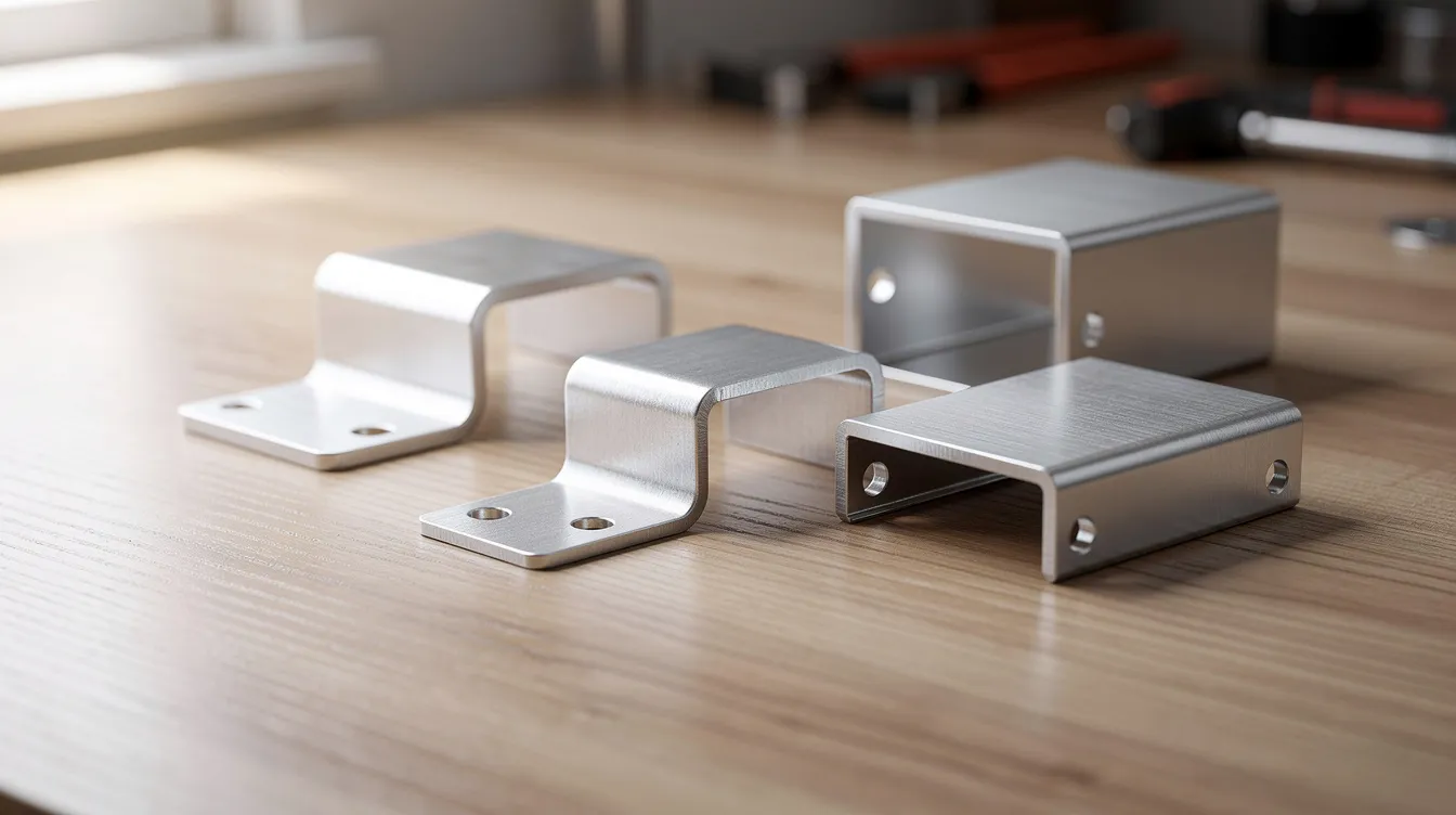
Materials and Thickness Ranges Anebon Bends Regularly
Anebon bends a wide range of sheet metals for overseas OEMs in automotive, robotics, medical, and electronics sectors – from thin covers under 1 mm to structural brackets over 6 mm. Bending can produce parts from materials up to 20 mm thick, though most OEM work falls in the 0.5–6 mm range.
Steels
Mild steel is the most commonly used bending material due to its excellent formability, availability, and lower cost. Common grades include SPCC, Q235, and carbon steel variants. Cold rolled steel with consistent thickness bends cleanly and predictably.
Stainless steel contains at least 10.5% chromium for corrosion resistance, making grades like 304 and 316 popular for medical, food-processing, and marine parts. Typical bent thicknesses range from 0.8 to 3 mm, though thicker materials are feasible with appropriate radius. For specific techniques, see our guide on how to bend stainless steel sheet metal.
Galvanized steel has a zinc coating for enhanced corrosion resistance. It bends well, but tight bends can crack the coating – use a radius of at least 1× thickness and consider post processing touch-up on exposed edges.
Aluminum Alloys
Aluminum alloys like 1060 are highly workable for bending due to their softness. For OEM parts, 5052-H32 is the workhorse – good formability, corrosion resistance, and a minimum bend radius of about 1× thickness. Aluminum 6061-T6 is stronger but harder to bend; it needs 2–3× thickness radius and careful grain orientation. Temper matters: 6061-O or T4 bends far more easily than T6. Learn more in our guide on how to bend aluminum sheet metal.
Other Materials
Copper is soft and easily bent, ideal for electrical applications like bus bars and connectors. Brass is valued for its aesthetic appeal and ease of fabrication, finding use in decorative hardware and instrument housings. Titanium is occasionally bent for aerospace or medical parts, but requires large radii and careful process control.
Anebon can advise on material choice and uniform thickness for projects that mix CNC machining, laser cutting, and sheet metal bending. ISO 9001:2015 and ISO 14001:2015 certifications support consistent quality and environmental management across all material handling and bending operations.
Precision, Tolerances, and Quality Control for Bent Sheet Metal
Dimensional control separates acceptable bent metal sheet parts from ones that fit an assembly perfectly. Here is what to expect from a precision fabrication partner.
Typical Tolerances
|
Parameter |
Standard Range |
|---|---|
|
Bend angle |
±0.5° to ±1.0° |
|
Flange / leg length (< 150 mm) |
±0.1 to ±0.2 mm |
|
Flange / leg length (> 150 mm) |
±0.2 to ±0.3 mm |
|
Complex parts with multiple bends |
Stack-up reviewed per assembly |
Stainless steel and high strength materials may have wider angular tolerances due to springback behavior. Bending can achieve accuracy levels of ±0.05 mm on CNC equipment with closed-loop angle sensing, though ±0.1 mm is more typical for production runs.
How Repeatability Is Achieved
-
CNC brake presses with programmable backgauges position material consistently for each bend
-
Crowning systems correct deflection across long dies
-
Angle sensors adjust ram depth in real time for consistent results
-
Laser-cut blanks with tight dimensional accuracy ensure the starting flat pattern is correct before the bending process begins
Inspection Practices
-
First-article inspection (FAI): the first pieces are measured for all critical dimensions, angles, and radii
-
In-process checks: periodic sampling during production to catch drift before it compounds
-
Final inspection with documented reports, required by OEM customers in aerospace, medical, and electronics sectors
-
Dedicated angle gauges and fixtures verify that each bend meets drawing specs
Anebon integrates bending with other processes – CNC machining, tapping, surface finishing – while maintaining controlled stack-up tolerances so that complex parts assemble correctly.
From CAD to Bent Part: How Anebon Supports Your Project
Anebon’s workflow takes your design from a digital file to a finished bent part with minimal friction.
1. CAD input. Customers submit files in STEP, DWG, or DXF format with full geometry – flanges, bend lines, hole features, material spec, and sheet thickness. The more complete the input, the faster the turnaround.
2. Engineering review and DFM feedback. Anebon’s engineers review flat patterns for bend allowance, bend deduction, hole-to-bend distances, and tooling feasibility. If a feature is at risk – say a hole too close to a bend, or a radius too tight for the specified material – they suggest adjustments to reduce cost and improve manufacturability. This collaborative feedback at the design stage prevents expensive surprises in production.
3. Prototyping. Anebon offers rapid prototyping in small batches using the same bending method and tooling that will be used in full production. Parameters learned during prototyping – actual springback, k factor confirmation, surface behavior – are recorded in a material database and applied to the production run for consistent results.
4. Production. Full-volume runs use CNC brake presses as an automated process, with all parameters locked in from the prototype phase. This minimizes lead time and risk for overseas OEM clients who cannot afford variation between prototype and production bent parts.
The goal is to help you bend metal once, correctly, and scale from there – not to iterate through rounds of rework. For an overview of custom precision sheet metal bending parts that Anebon produces, visit our capabilities page.
Instant Pricing and How to Request a Quote for Bent Sheet Metal Parts
Getting a price for your bent sheet metal parts should not require weeks of back-and-forth. Anebon’s sales engineering team provides fast, competitive quotes based on your submitted drawings and specifications, with instant pricing turnaround for standard configurations.
What to Provide for an Accurate Quote
-
Material type and temper (e.g., mild steel SPCC, stainless 304, aluminum 5052-H32)
-
Sheet thickness
-
Inside bend radius and number of bends
-
Bend angles and overall part dimensions
-
Quantity – prototype vs. production
-
Surface treatment or finish (powder coat, anodize, plating, paint)
-
Tolerance requirements or any inspection/certification needs
Typical Lead Times
-
Prototypes: typically delivered in days to 1–2 weeks depending on complexity
-
Production batches: 1–4 weeks depending on quantity, finishing, and inspection scope
-
Complex parts requiring specialized tooling or post processing may take longer
Why Start with Anebon
Anebon’s integrated workflow – laser cutting, CNC machining, sheet metal bending, and finishing – means you deal with a single supplier rather than coordinating multiple vendors. This keeps part quality high, timelines short, and costs transparent. CNC bending is cost-effective for low- to medium-volume production, and Anebon’s in house capabilities mean fewer handoffs and less risk.
Ready to move forward? Send your CAD files – STEP, DWG, or DXF – to Anebon for free manufacturability feedback and a competitive quote. Whether you need to bend sheet metal for a single prototype or thousands of production parts, getting expert DFM input before you commit to tooling is the fastest way to reduce waste, avoid rework, and deliver bent sheet metal parts that fit the first time.