Mastering SolidWorks Sheet Metal: A Practical Guide for Beginners
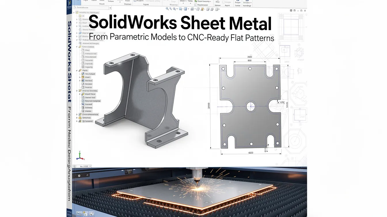
SolidWorks Sheet Metal: From Parametric Models to CNC-Ready Flat Patterns
Introduction to SolidWorks Sheet Metal Design
SolidWorks sheet metal is the go-to parametric environment for engineers who need to design parts that will be laser cut, punched, and bent on a press brake. The module handles everything from simple brackets and chassis walls to complex enclosures, HVAC ducting, machine guards, and medical device housings. Its strength lies in generating an accurate flat pattern directly from the 3D model, giving fabricators the exact blank shape and bend data they need to manufacture the part without guesswork.
The design process bridges CAD and production: you model a folded sheet metal part, SolidWorks calculates the flat development using your bend radius, k factor, and material properties, then you export dxf files or DWG drawings for CNC programming. When those parameters match the shop floor, the result is fewer iterations, less scrap, and faster delivery.
At Anebon Metal Products Limited, we use SolidWorks sheet metal models daily to support overseas OEMs from prototype through high-volume production. This article gives practical, manufacturing-focused guidance on the features, methods, and bend parameters that determine whether your flat pattern will produce an accurate finished part.
Getting Started: Activating the Sheet Metal Environment
Always start in the sheet metal module for accuracy. The dedicated environment ensures every feature you add carries correct bend data and produces a valid flat pattern. Sheet metal thickness is defined during part creation, and getting this right at the beginning prevents costly rework downstream.
To activate the sheet metal tab in the command manager, right click any existing tab in the CommandManager toolbar and select “Sheet Metal.” This gives you access to base flange, edge flange, hem, miter flange, lofted bends, and all related tools in one place.
Before sketching anything, configure your default sheet metal properties in the Sheet-Metal1 feature: set sheet thickness, default bend radius, relief type, and your preferred bend allowance strategy (k factor, bend allowance, or bend deduction). These sheet metal parameters propagate to every subsequent feature, so matching them to your fabricator’s tooling at this stage saves time later.
Core Sheet Metal Features: Base Flange, Flanges, and Bends
SolidWorks offers three main methods to create a sheet metal part: the base flange method, the insert bends method, and the convert to sheet metal method. Each handles a different starting point, but all produce the same result – a foldable body with a valid flat pattern. Sheet metal tools automate calculations for bends and reliefs, so once you pick the right method, the software does most of the heavy lifting.
Edge flange, miter flange, and hem features build geometry outward from existing edges. These features automatically inherit thickness, bend radius, and material settings from the parent sheet metal feature, keeping your sheet metal designs consistent without manual input at every step.
Base Flange Method
The base flange method starts with a 2D sketch on a reference plane. You draw a fully defined profile, then apply Base Flange/Tab to generate the first sheet metal body. For a closed contour, SolidWorks extrudes it into a flat plate at the specified thickness. For an open sketch, the base flange method can create bends automatically along the sketch line, producing a multi-bend shape in a single feature.
Choosing sketch plane orientation and origin matters: set the model origin to match CNC machine coordinates so the resulting flat pattern aligns with nesting and datum references. This flange method is preferred for most brackets, covers, and chassis where the design intent starts from a flat shape with flanges added later.
Insert Bends Method
Insert bends requires existing solid geometry to add bends. You start from a thin-walled solid body that has been shelled to constant wall thickness using the shell function, which gives constant wall thickness for conversions. Then you select a fixed face – the face that stays stationary in the flattened state – and pick edges that will become bend locations.
Rips define gaps between adjacent flanges in insert bends, allowing closed corners to open so the part can flatten. You choose between butt or overlap corner treatments depending on your sheet metal fabrication requirements. This method works well for legacy models that were not created in the sheet metal module but need manufacturable flat patterns.
Convert to Sheet Metal Method
Convert to sheet metal requires a solid body as input. Unlike insert bends, the solid does not need to be shelled first – you specify thickness and bends during conversion. You pick a base face (which becomes the base flange), then select edges to convert into bends and flanges.
This approach is useful for imported geometry (STEP or IGES) or complex shapes like hoppers, chutes, and funnels that are easier to model as a solid body first. Common pitfalls include inconsistent wall thickness, fillets smaller than the intended bend radius, and overlapping faces that prevent valid flattening. It is essential to maintain consistent thickness in sheet metal design to avoid these issues.
Sheet Metal Parameters: Thickness, Bend Radius, K Factor, and Bend Allowance
The neutral axis – an imaginary plane inside the material that neither stretches nor compresses during bending – is the reason flat pattern length differs from outside dimensions. SolidWorks offers multiple bend calculation methods: k factor, bend allowance, bend deduction, and bend tables. The method you choose and the values you enter must match your shop’s press brake tooling and material behavior, or the flat pattern will be wrong.
Bend radius equals the internal radius created during bending. A general starting rule is that inside bend radius should be at least equal to material thickness. For harder alloys like 6061-T6, aim for 2T–3T or higher to avoid cracking.
Understanding K Factor in SolidWorks
K-factor determines the ratio of neutral axis to material thickness – specifically, t / T where t is the distance from the inner face to the neutral axis and T is the total thickness. Typical ranges serve as a starting direction:
|
Material |
K Factor Range |
|---|---|
|
Cold-rolled steel |
0.30–0.40 |
|
Aluminum alloys |
0.38–0.45 |
|
Stainless steel |
0.35–0.50 |
These values are guidance, not absolute rules. You set k factor in the Sheet-Metal feature, and it affects the automatic flat pattern calculation for every bend in the part. The best practice is to align k factor values with data determined from sample bends made on the actual press brake used for production.
Bend Allowance, Bend Deduction, and Bend Radius
Bend allowance is the arc length along the neutral axis consumed by a bend. Bend deduction is the difference between the sum of flange lengths and the resulting flat pattern length. Bend allowance varies with bend angle, radius, and material – SolidWorks can use either method depending on the manufacturer’s standard formulas.
Selection of default inside bend radius has a direct impact on cracking, springback, and tooling wear. For example, soft aluminum alloys can tolerate an inside radius of 1× thickness, while 7075-T6 may need 6× thickness. We recommend that OEM designers obtain bend deduction or k factor recommendations from the fabricator early in the design process so that ensure bend calculations match overall dimensions for accuracy.
Using Gauge Tables and Material Standards
Gauge tables standardize material thickness in SolidWorks by mapping standard gauge numbers to exact thickness, bend radius, and allowance values in an Excel spreadsheet. SolidWorks includes default gauge tables for common materials stored under the installation directory. Using gauge tables prevents errors in material thickness entry by removing manual data input from the equation.
Custom gauge tables can be created in Excel for specific needs – for example, to mirror Anebon’s internal production standards for alloys like 5052-H32 or 304 stainless in specific gauges used on current projects. Enable “Use gauge table” in the Sheet-Metal feature and select the correct table for your material.
Gauge tables ensure uniform data across design and fabrication. When your entire team references the same table, every flat pattern is derived from identical assumptions. For teams working with offshore manufacturers, sharing and standardizing gauge tables keeps CAD and shop-floor expectations synchronized. SolidWorks also provides tools for real-time cost calculation, which can leverage gauge table data for estimating material consumption.
Advanced Features: Forming Tools, Reliefs, and Secondary Operations
Modern sheet metal components often include louvers, dimples, embosses, and vents. Forming tools in SolidWorks are stored in the Design Library. You apply them by dragging and dropping them onto a sheet metal face – the tool adapts to metal thickness and updates the flat pattern with punch locations and deformation outlines.
Relief types include tear, obround, or rectangular. Corner reliefs prevent material tearing where two flanges meet around a bend. The choice depends on geometry and aesthetics: tear reliefs are minimal, rectangular reliefs are easiest to manufacture, and obround reliefs split the difference.
For downstream processes, Anebon supports PEM insertion, spot welding, powder coating, anodizing, and plating. These should be indicated in your drawings or model annotations so fabrication planning can account for them.
Creating and Managing Custom Forming Tools
To create custom forming tools, model the punch shape, then designate faces to remove, faces that stop the tool, and positioning faces. Save the tool as a .sldftp file in a designated Forming Tools folder so SolidWorks recognizes it in the Design Library.
Use clear naming conventions and a shared store location so large engineering teams can access and reuse custom forming tools across multiple projects. Anebon can replicate or validate these custom forms with matching press tooling or CNC punch tooling, ensuring what you design in CAD can be produced on the shop floor. For guidance on physical forming processes, our resource library covers common techniques.
From 3D Model to Flat Pattern, DXF, and Production
The Flatten feature unfolds the model, checks for overlapping faces, and generates a flat pattern configuration. Validate flat patterns using the Flatten feature in SolidWorks before sending anything to production. Check that all bends unfold without issues before exporting – any overlap or missing relief signals a geometry problem that will cause scrap.
Before export, verify bend lines, relief sizes, hole-to-bend distances (minimum of bend radius + 1.5× thickness for round holes), and overall blank size. Minimum flange length should be at least 3× material thickness to accommodate press brake tooling.
Export flat patterns as dxf files for fabrication. Recommended export settings: export only flat pattern geometry with no hidden lines, and use layer mapping to distinguish bend-up from bend-down lines. The software produces DXF/DWG files ready for CNC machines or laser cutting. Proper origin placement in the flat pattern helps CNC nesting and reduces material waste. For more on cutting methods and material efficiency, consider how your flat pattern shape affects nesting on standard sheet sizes.
Validating Manufacturability and Tolerances
Run a quick DFM check before release: verify minimum flange lengths versus tooling limits, hole distances from bend lines, and clearance for hardware such as PEM fasteners. Routine verification checks increase accuracy and reduce rework across every production run.
Tight tolerances – for example ±0.1 mm on bend-to-hole locations – may require combining sheet metal with secondary CNC machining. Anebon’s standard sheet metal tolerances are ±0.005 inch (≈ ±0.127 mm) for edge-to-edge and hole-to-hole features, with tighter values available by mutual agreement. Involve the manufacturing partner early to confirm achievable tolerances, preferred bend sequences, and suitable materials. Our engineering team routinely reviews customer SolidWorks sheet metal models and flat patterns before production to catch issues that would otherwise cause delays.
Integrating Sheet Metal with Weldments, Assemblies, and Design Automation
Combining sheet metal and weldment modules makes sense for machinery frames with sheet metal guards or control enclosures. Top-down parametric modeling using a master sketch lets you control dimensions across multiple sheet metal components in one part file or assembly, keeping design intent intact as sizes change.
Configurations, design tables, and equations enable automation of product families – for example, a series of sheet metal junction boxes with different widths and heights but identical manufacturing rules. This approach scales well for OEM programs where a device family shares common bend rules and gauge tables but varies in overall shape and length.
Anebon supports such parametric workflows by maintaining consistent bend rules, gauge tables, and material libraries across all size variants, so you can drop a new configuration into production without re-qualifying the manufacturing process.
How Anebon Supports SolidWorks Sheet Metal Projects
Anebon Metal Products Limited operates from Dongguan, Guangdong, China, with ISO 9001:2015 and ISO 14001:2015 certifications and production experience since 2010. We function as a technical manufacturing partner – not just a quoting engine – for overseas OEM teams and R&D engineers.
Our integrated capabilities complement SolidWorks sheet metal design end to end: CNC laser cutting, CNC punching, press brake forming, CNC machining of secondary features, die casting, and surface treatments including anodizing, powder coating, and plating. We provide DFM feedback on bend allowance, k factor, gauge selection, and flat pattern optimization before production begins.
If you have a SolidWorks sheet metal file or flat pattern ready for review, send it to our engineering team for a detailed manufacturability assessment and quotation.
FAQ: SolidWorks Sheet Metal and Manufacturing
What is the difference between k factor and bend allowance? K factor is a dimensionless ratio describing where the neutral axis sits within the material thickness. Bend allowance is the calculated arc length along that neutral axis for a specific bend. K factor is an input; bend allowance is the output SolidWorks uses to compute flat pattern length.
How do I choose the right bend radius? Start with inside bend radius equal to material thickness (1T). For harder alloys or thicker gauges, increase to 2T–3T or more based on the material’s minimum bend radius chart.
How do I export a flat pattern for laser cutting? Use the Flatten feature to unfold the model, then File > Save As > DXF. Select “Flat pattern” geometry only, enable bend line layers, and exclude hidden lines.
What data does a manufacturer need besides the SolidWorks file? Material grade and temper, sheet thickness, surface finish requirements, tolerance callouts, hardware insertion locations, and quantities. A dimensioned drawing with GD&T is also recommended.
Why does my solid body fail to convert to sheet metal? The most common cause is inconsistent wall thickness. Use the shell function to create uniform walls before conversion, and ensure no fillets are smaller than your target bend radius.
Should I use SolidWorks default gauge tables or request a custom one? Request a custom gauge table from your fabrication partner whenever possible. Default tables are a reasonable starting point, but production accuracy improves when the table reflects the actual tooling and material on the shop floor.
Can Anebon help calibrate my k factor values? Yes. We routinely produce sample bends on specific materials and gauges, measure the results, and provide calibrated k factor and bend allowance data that you can input directly into your SolidWorks gauge table.
Summary: Best Practices for Reliable SolidWorks Sheet Metal Designs
Start every sheet metal part in the dedicated sheet metal module, use realistic bend radius and k factor values matched to your fabricator’s tooling, and always validate the flat pattern before release. These three habits eliminate the majority of fit and tolerance issues in production.
Key takeaways:
-
Use gauge tables to standardize material thickness entries and bend data across your team.
-
Validate flat patterns before exporting for fabrication – check for overlapping faces, missing reliefs, and correct blank dimensions.
-
Maintain minimum hole-to-bend distances of bend radius + 1.5× thickness.
-
Keep flange lengths at 3× material thickness or greater to suit press brake tooling.
-
Involve your manufacturing partner early to confirm achievable tolerances and preferred bend sequences.
-
Use the Flatten feature to check bend unfold accuracy on every revision.
Accurate sheet metal design in SolidWorks directly translates into fewer iterations, lower scrap rates, and faster lead times for OEM production. Anebon can take your SolidWorks sheet metal models from concept through prototyping to high-volume, ISO-certified manufacturing – request a quote to get started.