Mastering Sheetmetal Welding: Essential Techniques for Every Welder
Sheet Metal Welding: Methods, Challenges, and Best Practices for Precision Fabrication
Introduction to Sheet Metal Welding
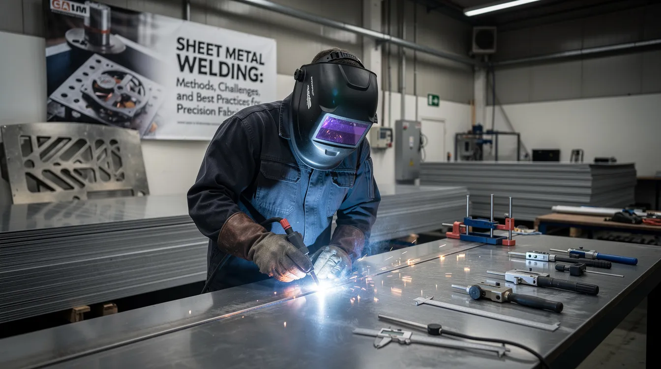
Sheet metal welding is a process of joining thin metal sheets using localized heat, and it sits at the heart of modern precision manufacturing. Whether you are producing electronic enclosures, medical device housings, automotive brackets, or robotics frames, the ability to weld thin sheet metal cleanly and consistently determines how well the final product performs-and how much it costs to make.
What makes welding thin sheet metal so different from thick plate work is the margin for error. Thin sheet metal is typically under 6 mm thick, often in the 0.5 to 3 mm range. At these gauges, there is very little thermal mass to absorb and dissipate heat. Too much heat burns a hole. Too little heat leaves a weak weld. The window between the two is narrow, and hitting it repeatably across hundreds or thousands of parts is the challenge that separates capable fabricators from the rest.
This guide covers practical sheet metal welding techniques used in OEM production lines: MIG, TIG (tungsten inert gas), resistance spot welding, and specialized methods like laser welding. Common welding methods include MIG, TIG, and spot welding, and each serves a distinct role depending on material, thickness, finish requirements, and volume. Anebon Metal Products Limited, an ISO 9001:2015 and ISO 14001:2015 certified precision sheet metal fabrication provider based in Dongguan, China, has been supporting overseas OEMs with welded sheet metal components since 2010-from single prototypes through high-volume production runs.
What Is Sheet Metal Welding?
At its core, sheet metal welding means joining metal sheets under approximately 6 mm thickness through localized melting and fusion. The typical sheet metal thickness range in OEM environments falls between 22 and 10 gauge (roughly 0.8–3.0 mm), though thinner and slightly thicker materials are common depending on the application. Industrial uses span electronics chassis, medical housings, instrument brackets, equipment cabinets, and structural frames.
Welding thin sheet differs fundamentally from welding thick plate. Thin materials heat up fast, conduct that heat rapidly through the entire part, and cool unevenly-creating stress that leads to warping and burn through. The narrow heat input window demands precise control of every parameter: current, voltage, travel speed, and filler selection. Surface finish matters too, because welds on sheet metal parts are often visible, requiring minimal post-weld grinding.
Within a full sheet metal fabrication workflow, welding is typically preceded by laser cutting or CNC punching, followed by bending and forming, and completed with surface treatments like powder coating or anodizing. Understanding how the welding process fits into this sequence is critical for getting the design, tolerances, and finish right.
How Sheet Metal Welding Fits into OEM Fabrication
A typical OEM project flow begins with a DFM review, where fabrication engineers analyze 3D models for manufacturability. From there, flat patterns are developed, blanks are laser-cut, parts are formed on press brakes, and then assemblies move to the welding area. After welding, surface treatment and final inspection complete the process.
Weld joint design decisions happen early-during the DFM stage. Engineers decide where to place tabs, slots, flanges, and locating features that will stabilize thin panels during welding and ensure repeatable positioning. For example, a 1.5 mm 304 stainless steel enclosure with TIG corner welds might incorporate interlocking tab-and-slot features along its edges. These features self-locate the panels, reduce fixture complexity, and minimize gaps at the joint-all of which improve weld quality.
Anebon supports design engineers with DFM feedback specifically aimed at reducing weld distortion and assembly cost. Recommendations might include relocating a weld seam away from a precision hole, adding a stiffening flange to prevent panel flex, or changing a butt joint to a lap joint for more forgiving heat management.
Core Sheet Metal Welding Methods
Choosing the right welding method for thin sheet metal depends on four variables: the base material, the sheet metal thickness, the required cosmetic finish, and production volume. Each method brings distinct advantages in speed, heat control, appearance, and automation-friendliness.
MIG welding is fast and efficient for thin sheet metal, making it a workhorse for steel and stainless steel components. TIG welding offers superior control for thin materials and produces the cleanest beads. Spot welding dominates high-volume overlap joints. Specialized methods like laser welding and plasma arc welding serve niche requirements where conventional arc welding cannot meet distortion or precision targets. Later sections cover the parameters-shielding gas, heat input, travel speed-that cut across all processes.
MIG Welding for Sheet Metals
MIG welding, formally known as gas metal arc welding (GMAW), uses a continuous wire electrode fed through a welding gun alongside a shielding gas to protect the weld pool from atmospheric contamination. The process is also referred to as metal inert gas welding, though in practice the gas mix usually includes carbon dioxide alongside argon.
MIG welding is ideal for thin sheet metal in the 0.8–3 mm range, particularly mild steel and stainless steel panels, industrial cabinets, and automotive structures. For welding thin sheet, operators use short-circuit transfer mode, which briefly shorts the arc to the workpiece, keeping heat input low. Smaller wire diameters-typically 0.6–0.8 mm (0.023–0.030″)-are preferred because they require less current to melt and deposit.
MIG pros for thin gauge sheet metal:
-
Higher deposition rate than TIG, reducing cycle time
-
Easier to learn and automate for consistent production
-
Good for long seams and continuous welds on cabinets and panels
MIG cons for thin gauge sheet metal:
-
Less precise heat control than TIG, increasing burn-through risk on very thin materials
-
More spatter, which may require post-weld cleanup
-
Bead appearance typically requires more finishing for cosmetic applications
For a deeper look at technique, see our guide on how to MIG weld sheet metal.
TIG Welding (Tungsten Inert Gas) for Precision Sheet Metal
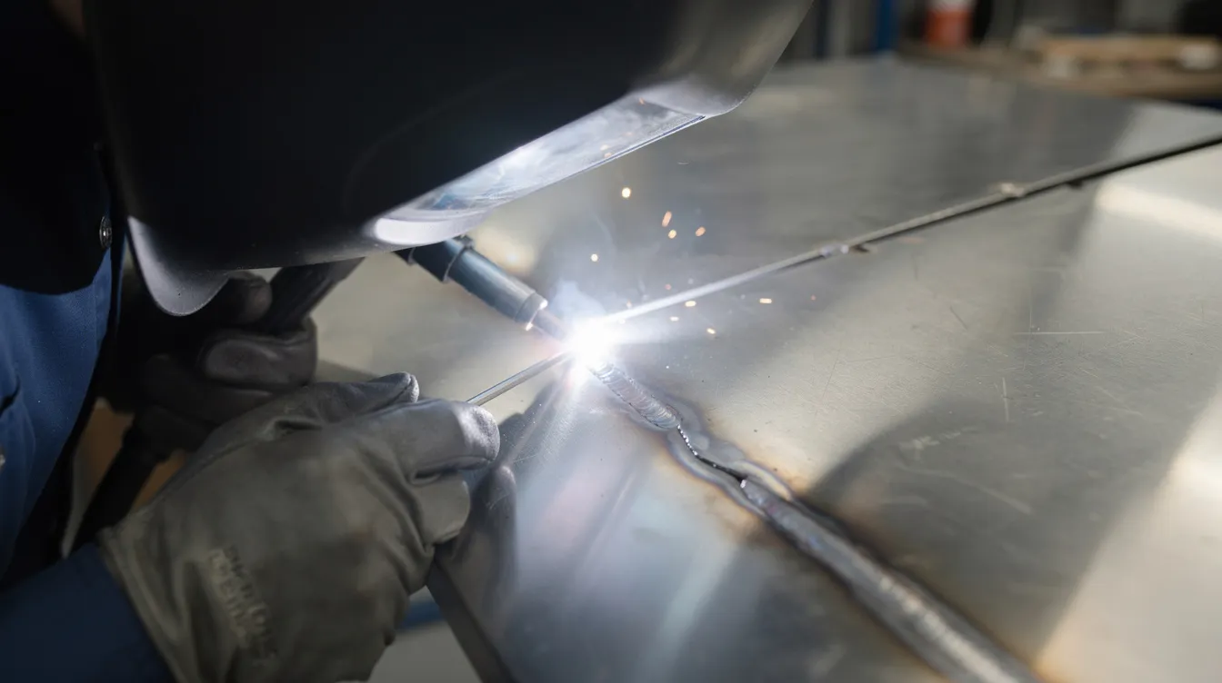
TIG welding uses a non consumable tungsten electrode to create the arc, with a separate filler metal rod added manually or by wire feeder, and pure argon as the shielding gas. This separation of heat source and filler gives TIG welders extraordinary precise control over the weld pool, making TIG welding the preferred sheet metal welding process for visible seams and cosmetically demanding assemblies.
TIG welding offers superior precision for thin materials. It is especially favored for stainless steel and aluminum sheet metal where bead appearance is critical-medical device housings, aerospace brackets, food-grade equipment. For ultra-thin sheet (0.6–1.0 mm), pulsed TIG with pointed ceriated or lanthanated tungsten electrodes allows the welder to maintain fusion without overheating. AC TIG is required for aluminum to break through the tenacious oxide layer.
The trade-off is speed. TIG is roughly 3–5× slower than MIG on equivalent joints, so it is typically reserved for applications where appearance or metallurgical integrity outweighs throughput. Anebon uses TIG on high-spec OEM enclosures and visible seams that require minimal post-grinding, selecting filler rods like ER308L for 304 stainless or ER4043 for aluminum alloys.
Resistance Spot Welding of Metal Sheets
Resistance spot welding joins overlapping metal sheets by clamping them between copper electrodes and passing high current for a fraction of a second. The resistance at the sheet interface generates heat, forming a molten nugget that solidifies into a strong metallurgical bond. No filler metal is required.
Spot welding is efficient for automotive body assembly and ideal for high-volume automotive manufacturing, where thousands of spots per vehicle are placed robotically. Typical sheet thickness per layer is 0.6–2.0 mm, with applications including battery tabs, brackets, and body panels. Nugget diameter is generally 4–5× the sheet thickness, with penetration reaching 70–80% into each sheet.
Advantages include extremely fast cycles, full automation compatibility, and minimal visible marking-just a small dimple on each side. The limitation is that spot welding only works for lap-type overlap joints and requires electrode access from both sides. For a comparison with mechanical fastening, see our article on spot welding vs riveting for high-load enclosures.
Other Welding Methods for Sheet Metal
Beyond MIG, TIG, and spot welding, several specialized processes serve niche requirements. Plasma arc welding is faster and more precise than TIG welding, using a constricted arc to produce narrower beads and deeper penetration at higher travel speeds. It is well suited for thin stainless seams in medical and food-processing equipment.
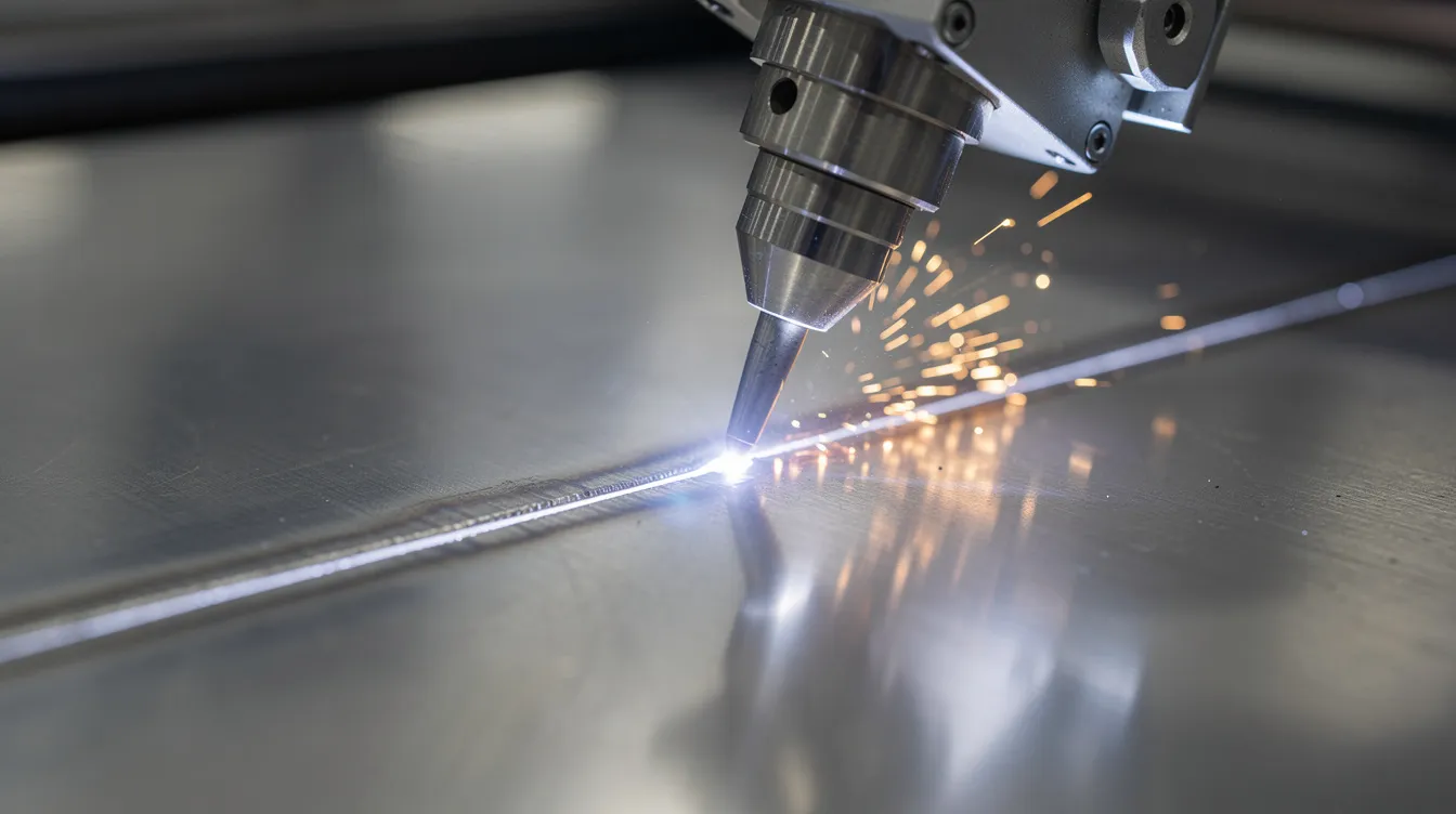
Laser welding minimizes heat distortion and is ideal for precision applications. Fiber lasers can join sheets as thin as 0.2 mm with extremely narrow heat-affected zones and travel speeds exceeding 500 mm/min on small seams. Micro-TIG fills a similar niche for delicate work on thin metal sheets where a full-size welding torch would be unwieldy.
These methods typically integrate with CNC positioning and robotics in advanced sheet metal fabrication shops. Anebon collaborates with partners where such processes are specified, ensuring that joint fit-up, fixturing, and tolerance requirements are met from the design stage forward.
Materials Used in Welding Sheet Metal
The base material shapes nearly every decision in a sheet metal welding process: the welding method, the filler material, the shielding gas, the travel speed, and the acceptable heat input. Common sheet metals in OEM work include mild steel, galvanized steel, stainless steel, and aluminum alloys. Each behaves differently under the arc due to differences in thermal conductivity, melting point, oxide formation, and coefficient of thermal expansion.
Matching filler metals, shielding gas, and welding technique to the base material is non-negotiable. A mismatch causes weak welds, corrosion, cracking, or cosmetic failures. The subsections below compare behavior across the three most common families and explain the surface preparation that makes consistent results possible.
Welding Sheet Steel vs. Stainless vs. Aluminum
Mild carbon steel sheet (e.g., DC01 cold-rolled) is the most forgiving material to weld. It has moderate thermal conductivity, a simple oxide layer, and good arc stability across MIG and spot welding processes. A 1.5 mm mild steel bracket can be MIG welded with 0.8 mm ER70S-6 wire, 75/25 argon/CO₂ gas, and relatively generous parameter windows.
Stainless steel sheet (304, 316) has lower thermal conductivity but higher thermal expansion-meaning heat stays concentrated near the weld and the metal moves more as it heats and cools. Distortion and discoloration are more pronounced. Filler must match the base: ER308L for 304, ER316L for 316. TIG is often preferred for visible stainless seams because it produces cleaner beads with less heat-induced discoloration.
Aluminum sheet (3003, 5052, 6061) presents the opposite thermal challenge: very high thermal conductivity spreads heat rapidly, while the oxide layer melts at a much higher temperature than the base metal. AC TIG is standard for aluminum to provide oxide cleaning action. MIG on very thin aluminum sheet is difficult and generally requires pulse weld modes and pure argon shielding. A 1.2 mm DC01 steel panel behaves very differently under the arc than a 1.2 mm 5052 aluminum panel-the aluminum demands faster travel, more aggressive oxide removal, and lower overall heat input.
Surface Preparation and Joint Fit-Up
Surface preparation is crucial for consistent welding results. Contaminants-oil, cutting fluid, zinc coatings, paint, and oxide layers-introduce gas into the weld pool, causing porosity and weak welds. Before any arc is struck, the metal surface near the joint must be thoroughly cleaned.
For steel, this means removing mill scale with light grinding and wiping with acetone. For aluminum, a dedicated stainless steel wire brush should be used immediately before welding to expose fresh metal beneath the oxide layer. On galvanized steel, the zinc coating must be removed within 25–50 mm of the weld zone to prevent toxic fumes and porosity.
Tight fit-up is equally important. Gaps must be kept below 0.5 mm for most MIG and TIG butt joints, and below 0.1–0.2 mm for laser welding. Accurate clamping reduces the amount of filler material needed, limits heat input, and reduces the risk of distortion. Anebon’s production includes standardized cleaning and deburring procedures before welding, ensuring that every part enters the welding area in a condition that supports clean welds.
Joint Designs for Welding Thin Sheet Metal
Joint design directly affects weld strength, accessibility for the welding torch or welding gun, and the degree of distortion when welding thin sheet metal. Common joint types for sheet metal include lap, butt, corner, T-joints, and edge joints. Edge joints are used for sheets placed side by side, though they are less common due to minimal material at the joint.
Engineers should consider assembly sequence and fixture access when selecting joints. Welded joints can provide structural integrity and strong connections, but only when the joint geometry suits the material thickness, the welding method, and the available access.
Lap and Plug/Slot Weld Joints
Lap joints involve overlapping sheets for better heat distribution. The extra thickness at the overlap makes the joint more forgiving-particularly on 0.8–1.2 mm sheets where a butt joint would be at constant risk of burn through. Fillet welds, spot welds, or plug welds are commonly used to join the overlapping metal pieces.
Plug and slot welds are made through pre-cut holes in the top sheet, filled with filler metal from above. They simulate the strength of a resistance spot weld when spot welding equipment is unavailable or when access from both sides is limited. A typical example: an equipment bracket joined with 3 mm diameter plug welds spaced every 20–30 mm on 1.5 mm sheet steel provides reliable strength without excessive heat buildup.
Butt, Corner, and T-Joints
Butt joints are commonly used for clean edge-to-edge welding on flat panel assemblies. They produce a flush surface that is ideal for visible seams, but they are unforgiving-any gap between the sheets invites burn-through, and fit-up must be precise. Corner joints create a right angle between two metal sheets and are standard for boxes and enclosures. They are frequently TIG welded for clean external corners that require minimal finishing.
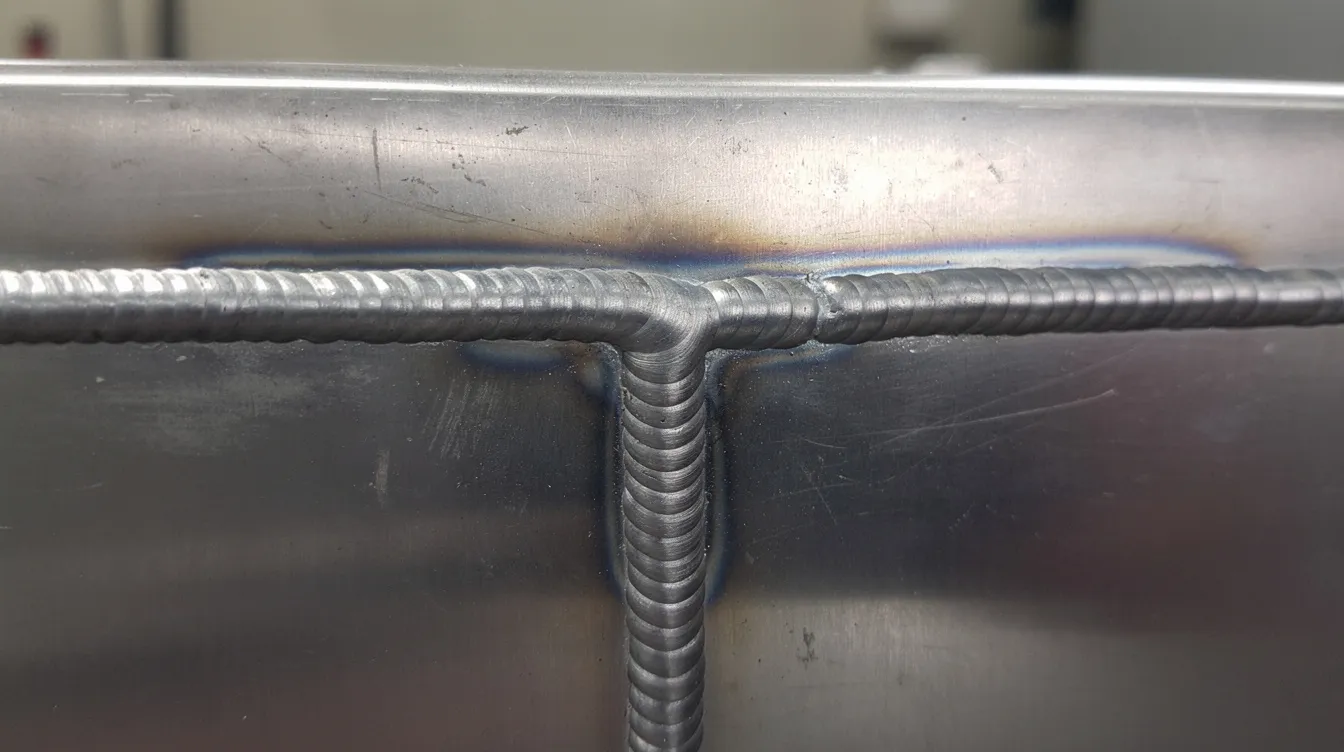
T-joints are formed when two sheets intersect at a right angle, commonly seen in structural frames, mounting flanges, and internal stiffeners. Designing small returns or gussets at the T-joint intersection helps stiffen thin sheet and distribute welding heat more evenly. For very thin gauge metal sheets (below 1.0 mm), a copper backing bar behind butt joints supports the molten weld pool, prevents burn-through, and acts as a heat sink to control distortion.
Key Parameters in Welding Thin Sheet Metal
Every sheet metal welding process is governed by a handful of parameters: current (amperage), voltage, wire speed or wire feed rate, travel speed, arc length, and shielding gas composition. Together, these determine the heat input delivered to the joint, the shape and penetration of the weld bead, and the extent of the heat-affected zone.
On thin sheet, small parameter adjustments produce large effects. A 5-amp increase that would be trivial on 10 mm plate can cause burn-through on 1.0 mm sheet. This is why establishing formal welding procedure specifications (WPS) matters for repeatable OEM production. The subsections below break down the key variables.
Heat Input, Travel Speed, and Distortion
Heat input is a function of amperage, voltage, and travel speed. Higher current or voltage increases it; faster travel reduces it. For sheet metal, the goal of every welding technique is to deliver just enough heat to achieve fusion without crossing into excessive heat territory that causes distortion or melt-through.
Practical measures to control heat input include using short weld beads rather than continuous runs, increasing travel speed, keeping arc length short, and employing intermittent welding patterns. For example, welding a 1.0 mm stainless cover might involve 10–15 mm stitch welds spaced 30–40 mm apart, alternating sides of the seam so the part has time to let the metal cool between passes. Heat distortion is a primary challenge in sheet metal welding, and managing it is less about eliminating heat than about distributing it intelligently.
Filler Metal and Wire Diameter Selection
Filler metal classification must match the base material: ER70S-6 for mild steel, ER308L for 304 stainless, ER316L for 316 stainless, and ER4043 or ER5356 for aluminum alloys. Using smaller diameter filler wire improves control and reduces heat input, which is why MIG wire diameters of 0.6–0.8 mm and TIG filler rods of 1.0–1.6 mm are standard for thin sheet work.
Oversized filler forces more current into the joint to achieve proper melting, which increases distortion risk and the chance of burn-through. For a mig welder running thinner wire, the machine can operate at lower amperage while still achieving smooth, consistent deposition. Anebon standardizes filler selections per material specification across production runs to ensure consistent joint performance from first article through final delivery.
Shielding Gas Choices for Welding Sheet Metal
MIG welding requires a shielding gas mixture of argon and CO₂ to protect the weld pool from atmospheric contamination. A shielding gas mixture of 75% argon and 25% carbon dioxide is common for MIG on carbon steel. Higher argon blends (85/15 or 90/10) produce a smoother arc, less spatter, and a cleaner bead profile-often preferred when welding thin sheet where spatter cleanup adds cost.
For TIG welding on stainless steel and aluminum, pure argon is standard. Argon/helium mixes can increase travel speed on thicker materials by raising arc energy. Gas flow rates are typically 20–25 CFH for standard nozzle sizes.
|
Material |
Process |
Recommended Gas |
Notes |
|---|---|---|---|
|
Mild steel |
MIG |
75% Ar / 25% CO₂ |
Standard, good penetration |
|
Mild steel |
MIG |
85% Ar / 15% CO₂ |
Less spatter, smoother arc |
|
Stainless steel |
TIG |
Pure argon |
Clean bead, minimal oxidation |
|
Stainless steel |
MIG |
Ar/He/CO₂ tri-mix |
Improved arc stability |
|
Aluminum |
TIG (AC) |
Pure argon |
Required for oxide cleaning |
|
Aluminum |
MIG |
Pure argon or Ar/He |
Pulse mode recommended |
Common Challenges When Welding Thin Sheet Metal
The main problems encountered in thin sheet metal welding are burn-through, warping and distortion, excessive spatter, porosity, undercut, and cosmetic defects. Heat application must be carefully controlled to avoid burn-through, and thin sheet reacts to thermal input far more dramatically than thick plate-making these defects more frequent and more damaging.
Most issues trace back to poor fit-up, incorrect parameters, or inadequate fixturing and heat management. The good news is that following established best practices significantly reduces rework and scrap in OEM production runs.
Burn-Through and Lack of Fusion
Burn-through occurs from excessive heat melting through the sheet, leaving holes in the workpiece. It is most common on gauges thinner than 1.2 mm and is caused by too much heat-too high amperage, slow travel, gaps in butt joints, or excessive weaving during welding. Welding thin sheet metal requires lower amperage settings to prevent burn-through, along with shorter weld lengths and tighter fit-up.
The opposite defect-lack of fusion-happens when insufficient heat or excessive travel speed prevents proper bonding of overlapping or abutting metal sheets. The molten metal doesn’t fully wet the base material, leaving a weak weld that may separate under load. Addressing both issues requires careful parameter calibration: enough heat to fuse, not enough to melt through. Lower amperage settings help prevent burn-through in thin sheets, while proper joint preparation ensures adequate fusion.
Warping, Distortion, and Panel Buckling
Warping happens due to rapid expansion and contraction of thin metal during and after welding. As the weld cools, it contracts, pulling adjacent sheet metal with it. On thin panels-equipment covers, door panels, large enclosure sides-this can cause bowing, twisting, or the familiar “oil-can” effect where flat surfaces pop in and out.
Weld sequence matters enormously. If all welds are placed on one side of an assembly first, the part will pull toward that side. Balanced welding patterns-alternating between opposite sides, working from center outward-help equalize shrinkage forces. Strong clamping and rigid fixtures restrain movement during welding, and backing bars act as heat sinks. Some distortion is inevitable; the goal is keeping it within design allowables, typically 0.5–1.0 mm of flatness deviation on large panels.
Porosity, Spatter, and Surface Quality Issues
Porosity-trapped gas pockets in the weld bead-weakens joints and can cause leak failures in housings and ducting. Common causes include contamination (oil, moisture, paint on the metal surface), poor shielding gas coverage from leaks or drafts, and excessive arc length that allows atmospheric gases to enter the weld pool.
Spatter and inconsistent bead appearance are cosmetic defects that increase grinding and finishing cost. They stem from too much heat, mismatched wire speed and voltage, or incorrect gas composition. Proper surface prep, correct gas selection, and stable welding technique-maintaining consistent arc length and travel speed-address all three problems simultaneously.
Techniques to Control Heat and Prevent Warping
Mastering heat management is the core welding technique for thin metal sheets. Every method described here-stitch welding, skip welding, pulse weld modes, and backing bars-serves the same purpose: delivering controlled heat to achieve fusion without accumulating too much heat in any one area.
Welding methods focus on minimizing heat input to prevent distortion. Before running production parts, welders should always use test coupons in the same material thickness and alloy to dial in parameters. What works on 1.5 mm mild steel will not work on 1.5 mm aluminum.
Stitch, Skip, and Tack Welding Techniques
Stitch welding means placing short weld segments (typically 10–15 mm) with unwelded gaps (30–40 mm) along the joint. Stitch or skip welding helps minimize distortion in thin materials by allowing partial cooling between segments. Skip welding takes this further by alternating positions-welding one end of a seam, then jumping to the opposite end, then filling the middle.
Stitch welding reduces cumulative distortion in thin sheet metal by preventing the linear heat buildup that causes long seams to shrink and bow. Tack welding establishes initial alignment with small, evenly spaced welds-typically 30–50 mm apart on 1–2 mm sheet metal components-locking geometry in place before full weld passes are made.
Using Backing Bars, Chill Plates, and Fixtures
Copper backing bars help absorb excess heat during welding by acting as a heat sink behind thin joints. A copper backing bar placed behind a butt joint on 1.0 mm stainless supports the weld pool, prevents burn-through, and pulls heat away from the sheet to reduce distortion. Aluminum chill plates serve a similar function.
Rigid fixtures, jigs, and strong clamping maintain panel flatness during welding sheet metal. Production tooling may integrate locating pins and clamping pads designed directly from the CAD model, ensuring repeatable positioning across hundreds of parts. Anebon designs custom fixtures for repeat OEM programs, maintaining tolerance and reducing rework on assemblies where flatness and dimensional accuracy are critical.
Leveraging Pulse Modes and Advanced Power Sources
Pulsed MIG and pulsed TIG alternate between a high peak current for penetration and a low background current for cooling. This cycle repeats many times per second, reducing average heat input by 20–30% while maintaining adequate fusion. The result on 0.8–1.5 mm sheet: narrower beads, reduced heat-affected zones, and significantly less risk of burn-through.
For example, pulsed MIG on 1.2 mm stainless steel can produce clean, consistent beads at travel speeds that would cause burn-through in conventional short-circuit mode. Inverter-based power sources used in Anebon’s shop enable fine low-amperage control essential for welding thin sheet metal applications, providing stable arc performance even at the bottom of the current range.
Welding Thin Sheet Metal: Step-by-Step Workflow
The following sections walk through a typical thin sheet metal welding operation from initial preparation through final inspection. The primary example covers MIG and TIG on 1.0–2.0 mm steel and stainless steel, with notes on aluminum variations where relevant. Proper setup and preparation improve welding quality and reduce defects at every stage.
From Preparation to First Arc
The first step is verifying the material type and thickness against the drawing. Confirm whether the part is mild steel, stainless, or aluminum, and check for any coatings or finishes that must be protected or removed. Clean edges thoroughly-use acetone to remove oils, a wire brush to remove oxide (stainless steel wire brush for aluminum), and light grinding to clear mill scale on steel.
Choose the joint type and welding method based on part function and access. A visible enclosure corner calls for TIG; an internal bracket lap joint works well with MIG or spot welding. Position components in a fixture or with temporary clamps, ensuring tight fit-up. Add initial tack welds from the center outward, spaced 30–50 mm apart. Before committing to production parts, perform test beads on scrap from the same batch of sheet metal to verify settings. Always wear appropriate PPE in the welding area-a welding helmet with proper shade rating, welding gloves, and a welding jacket. Keep a fire extinguisher accessible at all times.
Executing the Welds and Managing Sequence
When appearance is critical, start welding sheet metal by striking the arc on sacrificial run-on tabs rather than on functional surfaces. This avoids the irregular start puddle that forms when the arc first ignites. Alternate between opposite sides of the assembly to balance shrinkage-weld one corner, then the opposite corner, then fill intermediate sections.
Use short runs with pauses to let the metal cool between weld passes. Frequently check panel flatness and gap closure visually and by feel. Monitor arc sound continuously: a steady crackling indicates stable short-circuit transfer in MIG, while sputtering or popping suggests parameter issues. Bead width should remain consistent-widening indicates excess heat buildup, signaling the welder to increase travel speed or pause to cool. Proper technique means maintaining consistent stick-out distance, torch angle, and travel speed throughout each weld segment.
Post-Weld Finishing and Quality Checks
Post-weld processing may involve grinding or polishing for a smooth finish, depending on the cosmetic requirements. On stainless steel, discoloration from heat is removed by mechanical brushing or chemical passivation. On painted or powder-coated parts, weld beads may be blended flush with the surrounding surface.
Dimensional inspection follows: flatness checks across panels, overall length and width measurements, and functional checks like hinge alignment or door fit on welded enclosures. Visual acceptance criteria for OEM sheet metal welds typically include no visible porosity, undercut limits, and continuous fillet size. Anebon performs 100% visual inspection and sampling-based dimensional checks per ISO 9001:2015 procedures, with full documentation for customer review.
Automation and High-Volume Sheet Metal Welding
When production volumes increase, manual welding becomes a bottleneck for consistency and cost. Robotic MIG and TIG cells, resistance spot welding lines, and automated laser welding systems take over for repeat, high-volume sheet metal parts. Automated welding processes enhance production speed and quality by eliminating operator variability in travel speed, arc length, and weld placement.
Stable fixturing, consistent incoming material quality, and well-defined welding procedures are prerequisites for successful automation. Anebon supports the ramp from manual prototyping to semi-automated or fully automated welding as OEM programs move from first articles into production.
Robotic Welding in Precision Sheet Metal Fabrication
Typical robotic applications include perimeter welds on chassis, repetitive fillet welds on brackets, and multi-point welds on complex frames. Robots deliver repeatable motion paths, consistent travel speed, and programmable weld sequences that would be impractical for human welders to replicate shift after shift.
Offline programming directly from 3D CAD models minimizes downtime when changing over to new OEM parts. Weld sequence optimization-the order in which joints are welded to minimize distortion-is embedded in the program. Robotic welding is especially beneficial when tolerances on flatness and distortion are tight on large panels, where even small variations in human technique cause parts to go out of specification.
Integrating Welding with Upstream and Downstream Processes
Coordination between laser cutting, bending, welding, and surface finishing protects weld quality and final appearance. Sequencing decisions matter: welding before powder coating avoids heat damage to the finish, but the weld area must be clean for the coating to adhere properly. Welding after anodizing is generally avoided because the anodic layer must be removed at the joint.
Engineered tabs and slots cut on CNC lasers speed up fixturing and ensure consistent weld joint alignment part after part. Anebon’s one-stop approach-combining precision sheet metal parts production, CNC machining, and surface treatment under one roof-allows OEM customers to manage the full fabrication chain through a single vendor, reducing coordination risk and lead time.
Design for Manufacturability (DFM) Tips for Welded Sheet Metal Parts
The cheapest way to solve a welding problem is to design it out before the first blank is cut. Collaboration between OEM design teams and fabrication engineers early in the project prevents costly rework, reduces weld length, and positions joints where they are accessible and least likely to cause distortion.
The following subsections provide high-level best practices that design engineers can apply directly, whether they are designing robotics frames, medical housings, or EV battery enclosures.
Reducing Distortion Through Smart Design
Add ribs, flanges, or formed features to stiffen large flat panels before welding. A 400 mm × 400 mm flat panel in 1.2 mm stainless will distort noticeably; the same panel with two pressed ribs running across it resists warping far better. Orient welds symmetrically and break long seams into shorter sections where structural performance allows.
Where strong welded connections are needed on very thin surrounding sheet, consider adding thicker local pads or bosses at the joint. An electronics enclosure, for example, can be redesigned to use multiple short corner welds instead of one continuous perimeter weld-dramatically reducing cumulative heat and shrinkage while maintaining the structural integrity of the assembly.
Optimizing Joint Locations and Accessibility
Place welds where torches, welding guns, or robotic end-effectors have straight-line access. Awkward angles force welders to compromise on arc length, travel speed, and torch angle, producing inconsistent weld beads. Design tabs and slots that self-locate components, minimizing setup time and chances of misalignment.
Avoid welds directly adjacent to precision machined features, threaded inserts, or sensitive electronics mounting points. The heat-affected zone extends well beyond the visible bead, and excess heat can distort nearby holes or weaken press-fit features. As a guideline, keep weld seams at least 3× the material thickness away from precision features whenever the design allows.
Material, Finish, and Welding Method Selection
The intended finish drives welding method choice. A brushed stainless enclosure demands TIG with careful finishing; a powder-coated steel cabinet can tolerate MIG with moderate grinding. Choosing the alloy with weldability in mind saves headaches: 5052 aluminum welds readily, while 7075 is prone to cracking and generally avoided for welded brackets.
Involve your fabrication partner early to recommend combinations of base material, welding process, and post-treatment that meet both mechanical and cosmetic targets. Good upfront choices in material, finish, and welding method reduce total cost, lead time, and quality risks in OEM sheet metal programs. Stick welding, while common in structural steel work, is rarely used for thin sheet metal due to its high heat input and difficulty controlling the arc on thicker metals versus thin materials.
Quality Assurance and Standards in Sheet Metal Welding
Formal quality systems and documented welding procedures are not optional in OEM production-they are the foundation of repeatable weld quality. Anebon operates under ISO 9001:2015 and ISO 14001:2015 certifications, with formalized process controls covering every stage from incoming material inspection through final packaging.
Weld quality directly affects product reliability, safety, and long-term performance in industries like automotive, medical devices, and aerospace. A single porous weld in a sealed housing or an undersized fillet on a load-bearing bracket can lead to field failures that far exceed the cost of proper process control.
Inspection Methods for Welded Sheet Metal Assemblies
Visual inspection remains the first line of defense: trained inspectors check for surface defects, bead uniformity, undercut, and porosity on every welded assembly. Dimensional checks with gauges, calipers, or CMM verify flatness, alignment, and overall envelope dimensions on critical assemblies.
For fluid or air handling components-housings, ducting, sealed enclosures-leak testing confirms weld integrity. More advanced methods like dye penetrant testing (for crack detection on stainless), ultrasonic testing, or X-ray may be specified for safety-critical OEM parts. Inspection frequency is tailored to the project risk level and customer requirements, ranging from 100% inspection on critical dimensions to statistical sampling on less sensitive features.
Process Control, Documentation, and Traceability
Welding procedure specifications (WPS) document every parameter: current, voltage, travel speed, filler material, shielding gas type and gas flow rate, and welder qualification. These records ensure that what worked on the first article can be replicated on the thousandth.
Traceability practices include lot tracking of sheet metal, filler material, and shielding gas batches-so if a quality issue arises, the root cause can be traced back to specific inputs. Anebon maintains documentation and reporting capabilities for overseas OEM audits and PPAP-like submissions. Strong process control minimizes surprises when scaling from prototype to full production, giving OEM customers confidence that quality remains consistent as volumes increase.
When to Partner with a Professional Sheet Metal Fabricator
Outsourcing sheet metal welding makes sense when your project demands tight tolerances, high cosmetic requirements, complex multi-weld assemblies, or volume production that exceeds in-house capacity. A professional fabricator brings specialized fixtures, tuned welding procedures, qualified welders, and process documentation that would take months to develop internally.
Overseas OEMs often require precision in metal fabrication and welding operations that goes beyond what general-purpose job shops can deliver. A dedicated partner with experience across materials, processes, and industries reduces risk and accelerates time to market.
How Anebon Supports OEMs and Design Engineers
Anebon provides DFM review of welded sheet metal designs, rapid prototyping of welded assemblies, and scalability to batch or continuous production. Industries served include robotics frames, medical imaging housings, EV battery enclosures, and electronics chassis-all requiring reliable thin sheet metal welding on materials from mild steel to aluminum.
For overseas clients, Anebon offers English-language engineering support, consistent quality backed by ISO certifications, and clear lead-time commitments. Whether your welding project involves a single prototype enclosure or a production run of thousands, the process starts with sharing your CAD files and welding requirements. From there, Anebon’s engineering team provides a detailed quote, DFM feedback, and a manufacturing plan tailored to your specifications. Reach out to start a conversation about your next precision sheet metal fabrication program.