Mastering Sheet Bending: Techniques and Tips for Precision Results
Sheet Bending: Practical Guide to Bending Sheet Metal for Precision OEM Parts
Introduction to Sheet Bending
Sheet bending is a metal fabrication process used to deform sheet metal into precise angular shapes, curves, and flanges without removing material. For OEM manufacturers producing brackets, enclosures, instrument chassis, and medical device housings, it remains one of the most efficient ways to transform a flat metal sheet into a functional, load-bearing component. Rather than cutting away stock or welding separate flanges together, bending reshapes the workpiece using brake presses and rollers, preserving structural integrity in a single piece.
At Anebon Metal Products Limited, we have specialized in precision bending since 2010, serving overseas OEMs in aerospace, medical devices, automotive, electronics, and robotics from our facility in Dongguan, China. Our CNC-controlled bending process handles common sheet thickness ranges from 0.5 mm to 6 mm across mild steel, stainless steel, aluminum, copper, and brass, with common bend angles including 45°, 90°, and obtuse configurations.
This guide covers everything manufacturing engineers and design teams need to know about bending sheet metal for production parts:
-
Common bending methods (air bending, bottom bending, coining, roll bending, and more)
-
Key geometry concepts including bend radius, bend allowance, bend deduction, and k factor
-
Design rules for flange length, bend relief, and feature placement near bend lines
-
Material selection, springback compensation, and tolerance expectations
-
How to work with Anebon from flat pattern to finished bent parts
What Is Sheet Metal Bending?
Sheet metal bending is the process of plastically deforming a flat sheet beyond its material’s yield strength to create a permanent angle or curve. Sheet bending applies force to permanently deform metal along a bend line, and unlike machining, it does not change the material thickness significantly. The result is a permanent deformation that holds its angular shape after the tooling is removed.
Here is what defines the process and its basic setup:
-
A press brake (mechanical, hydraulic, or CNC servo-electric) holds a punch (top tool) and a die (bottom tool), typically a v shaped die or U-die. The punch drives the sheet into the die to create the bend.
-
Backgauges position the workpiece so that flange length and bend-to-feature distances are repeatable across parts.
-
The bending process creates stronger, stiffer bent sheet metal parts from a single piece of sheet metal compared with assembling multiple machined or welded components. Think of control panels, battery housings, or medical device enclosures that gain rigidity from formed flanges rather than added brackets.
-
The bend radius is the inside radius of curvature on the concave side of the bend. The outside radius equals the inside radius plus the material thickness. Choosing the correct desired bend radius matters because the bend radius affects material stress during bending. Too small a radius causes the outer fibers to crack; too large wastes material and may not meet fit requirements.
-
Most precision sheet metal parts for OEM components use cold bending at room temperature, which preserves surface finish and dimensional accuracy. Hot bending (heating above recrystallization temperature) is reserved for very thick plates or low-ductility alloys where cold forming would cause fracture.
Hot vs. Cold Bending in Sheet Fabrication
Understanding when to use hot versus cold bending helps you select the right bending process for your part’s requirements.
-
Hot bending heats the workpiece above its recrystallization temperature (roughly 800–1100 °C depending on alloy), reducing yield strength and increasing ductility. It is used for heavy structural beams, thick plate components for shipbuilding, or infrastructure sections where cold forming forces would be impractical. The trade-off is slower cycle time, surface oxidation risk, and potential changes to the material’s microstructure.
-
Cold bending operates at room temperature and is the standard for precision sheet metal used in electronics enclosures, medical carts, automotive brackets, and robotics frames. It delivers better surface finish, tighter dimensional accuracy, and no thermal distortion.
-
Strain hardening during cold bending actually increases the stiffness and hardness of the material in the bend zone. This is a benefit: flanges and formed profiles gain strength beyond the original shape of the sheet.
-
Anebon focuses on cold bending of sheet and light plate to maintain tolerances as tight as ±0.1 mm on bends when combined with CNC laser cutting. For parts that require hot forming or very thick plates, we advise customers case-by-case and can coordinate specialized processes.
Cold bending keeps surface finish intact and avoids the dimensional unpredictability that comes with heating and cooling cycles. For most OEM sheet metal parts under 6 mm thickness, it is the clear choice.
Bending Methods Used to Bend Sheet Metal
Different bending methods are chosen based on the required accuracy, desired bend radius, production volume, and surface finish expectations. Below are the common bending methods used in OEM sheet fabrication.
-
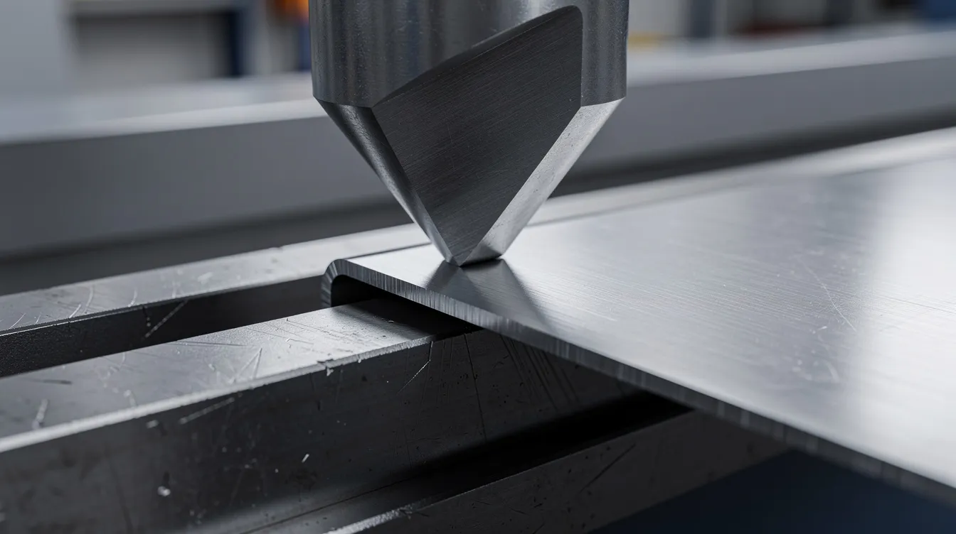
V-bending on press brakes is the most widely used die bending approach. V-bending is the most common method using a punch and die, where the punch pushes the sheet into a v shaped die. Common methods of sheet bending include air bending and roll bending, but V-bending on brake presses covers the vast majority of production work. Press brakes are commonly used machines for V-bending across nearly every sheet metal shop.
-
Air bending is the most flexible variant of V-bending. The punch presses the sheet partway into the die without bottoming out, leaving an air gap. By controlling ram depth, a single die can produce multiple bend angles. Air bending accounts for around 90% of bending jobs because it requires lower bending force and allows quick setup changes. The downside: greater springback and more sensitivity to material variation.
-
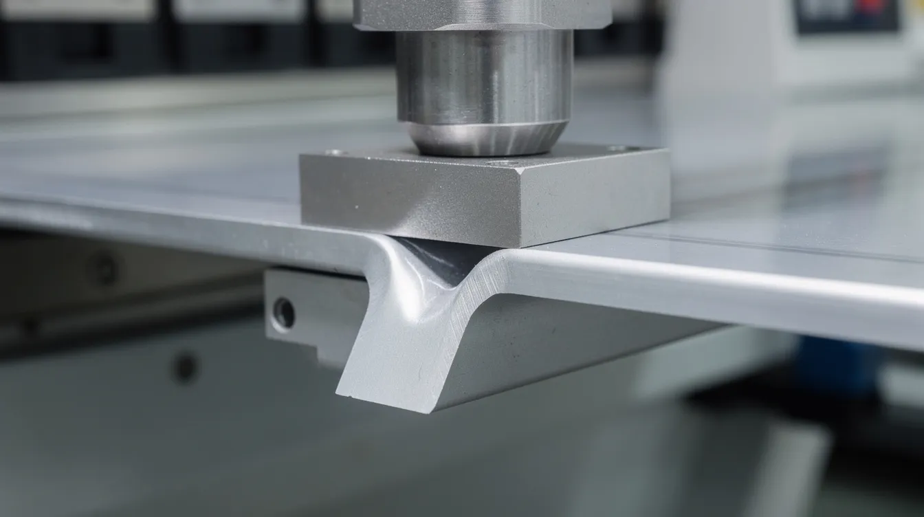
Bottom bending pushes the sheet firmly against the die surfaces. Bottom bending provides good precision and less springback compared to air bending, but it requires angle-specific tooling and higher tonnage. It is the go-to bending method when angular tolerance must be within ±0.25°.
-
Coining is a high-force variant of bottoming where the punch presses deeply into the material, essentially stamping the bend into the exact die profile. Coining requires high forces, about 5–8 times more than air bending, but delivers near-zero springback and excellent repeatability for tight bends and sharp angles.
-
Roll bending forms large curves or cylinders by passing material through rollers. It handles everything from thin duct panels to heavy plate. Rolling can bend materials from 1 mm to over 50 mm thick, making it suitable for cylindrical and conical shapes like machine guards, tanks, and architectural elements.
-
Step (bump) bending approximates larger bend radii by making a series of small successive bends on a press brake. It works when dedicated rolling equipment is unavailable but can leave visible faceting.
-
Folding is a method that uses a beam to bend sheet metal along a straight line. It is useful for long, shallow bends and panels where the sheet cannot be maneuvered easily on a press brake.
-
Wipe bending (edge bending) forms small flanges by clamping one side of the sheet and wiping the free side over a die edge. Rotary bending uses rotating dies to form bends without direct contact on the outer surface, making it ideal for non-marking bends on pre-painted or cosmetic panels. Note that bending can leave indentations or scratches on the material with standard tooling, so rotary bending or protective films are used when surface quality is critical.
At Anebon, our CNC hydraulic brake presses with multi-axis backgauges handle complex bend sequences. For guidance on which tooling suits your application, our engineers evaluate part geometry, material type, and volume before recommending the optimal method.
Key Geometry Concepts: Bend Radius, Bend Allowance & Bend Deduction
Getting geometry right is where bent parts either fit perfectly in assembly or require costly rework. Here are the concepts every design engineer should understand.
-
The inside bend radius (inner radius) is the curvature on the concave surface of the bend. The outside radius equals the inside radius plus the sheet thickness. Choosing a suitable bend radius prevents cracking, especially in harder alloys like 304/316 stainless steel or 7075 aluminum, where the material stretches significantly on the outer fiber.
-
The minimum bend radius should equal or exceed the sheet thickness to prevent cracking as a general rule. For mild steel and carbon steel, a radius of approximately 1× thickness works. For stainless steel (304), plan for 1.5–2× thickness. For harder aluminum like 6061-T6, use 3–6× thickness. Softer alloys like 5052-H32 allow tighter bends at around 1× thickness. Exact values depend on the alloy, temper, grain direction, and bending method.
-
The k factor is a ratio of the neutral line to material thickness. The neutral axis is the imaginary layer within the sheet that experiences no net stretching or compression during bending. The K-factor estimates sheet metal stretch during bending by locating where this neutral axis sits. K-factor varies based on material properties and bending method: mild steel ≈ 0.44, stainless ≈ 0.45, soft aluminum ≈ 0.38–0.42. K-factor typically ranges from 0.3 to 0.5 across common materials and processes. The K-factor also helps calculate springback in sheet metal bending, making it essential for predicting final bend angle accuracy.
-
Bend allowance is the arc length of the neutral axis in the bend region, representing how much material is “consumed” by the bend. The bend allowance formula is: BA = (π / 180) × bend angle × (inside radius + K × material thickness). This value is added to the flat lengths of each flange to determine the total flat pattern length.
-
Bend deduction is the amount subtracted from the sum of flange lengths to obtain the correct flat pattern length. It is the practical counterpart of bend allowance in CAD sheet metal modules and is critical for getting blanks cut to the right size.
Worked example: A 90° bend in 2 mm aluminum with a 2 mm inside radius and K-factor of 0.42:
BA = (π / 180) × 90 × (2 + 0.42 × 2) = 1.5708 × 2.84 ≈ 4.46 mm
This means the flat pattern must include 4.46 mm of arc length for that single bend. For a part with multiple bends, each bend adds its own allowance. Errors here compound quickly, which is why accurate bend allowance calculation matters for every project.
Anebon engineering can assist customers with bend allowance tables and K-factors tailored to their specific material and bending method, reducing trial-and-error and avoiding rework on first articles.
Springback, Tolerances, and Dimensional Control
Springback occurs when metals partially regain their original shape after bending load is removed. It is the elastic recovery portion of deformation, and every bent part experiences it.
-
Springback typically results in a 1–2° angle difference, meaning a part bent to 90° on the machine may open to 91–92° after unloading. Springback generally amounts to 1–2° of difference for mild steel in air bending; stainless steel can exhibit 4–7° of springback depending on grade and thickness.
-
The main drivers of springback are the material’s yield strength, material thickness, bend radius, and bending method. Air bending produces more springback than bottom bending or coining. Springback effects depend on material properties and bend radius: higher-yield materials and larger bend radii increase elastic recovery.
-
Compensation for springback can be achieved by overbending: programming the press brake to bend slightly past the desired angle so the part springs back to the target. For example, a 2 mm stainless steel part targeting 90° may need to be over bent to approximately 86–88° on the machine. CNC press brakes with angle measurement sensors automate this correction in real time.
-
Additional strategies include using specialized tooling with sharper punch radii, switching from air bending to bottoming or coining, and running test bends on sample coupons from the same material lot.
-
With accurate laser cutting or CNC punching of blanks combined with CNC-controlled ram depth and backgauges, Anebon maintains tight angular and dimensional tolerances on bent parts. Sheet metal bending achieves accuracy levels of ±0.05 mm on cut features, while typical economic tolerances for the bending process itself are ±0.5–1° on bend angle and ±0.2–0.5 mm on flange length depending on part size. Tighter tolerances can be negotiated for critical-to-function dimensions.
Define which dimensions are truly critical. Over-specifying tolerances across every feature increases cost and lead time without adding functional value.
Design Rules for Bending Sheet Metal
Good design-for-manufacturing around bend lines, flange geometry, and feature placement reduces cost, scrap, and lead time. Material properties influence bending force and final shape in sheet bending, so these rules account for real-world forming behavior.
-
Maintain uniform wall thickness and consistent thickness across the part. Uniform wall thickness ensures consistent bending behavior, predictable bending force, and a stable bend radius from one end of the bend to the other.
-
Observe minimum flange length requirements. As a starting guideline, flange length should be at least 3–4× the material thickness. For example, on 2 mm sheet steel, the minimum flange length is roughly 6–8 mm. If the flange is too short, it will slip off the die shoulder or deform unpredictably.
-
Keep holes, round holes, extruded holes, and slots away from bend lines. Holes too close to bends can cause deformation, with the opening elongating or collapsing. Holes and slots must be placed 2.5 to 4 times the material thickness away from bends. For a 1.5 mm sheet, that means at least 3.75–6 mm from the tangent line of the bend.
-
Include bend relief at the ends of bends to prevent tearing and distortion where a flange meets a cutout or edge. Relief width should be at least equal to the material thickness, and the shape can be rectangular or rounded. Without adequate relief, the sheet tears or buckles at the transition.
-
Standardize bend angles and bend radii. Using the same desired angle (90°, 45°, 135°) and the same inside radius throughout a design family minimizes tooling changes on the press brake. Every die swap costs setup time and money.
-
For parts with successive bends in the same direction, such as Z-bends or U-profiles, maintain enough spacing between bend lines for tooling access. The minimum distance between parallel bends depends on die geometry and punch presses clearance; as a baseline, separate flanges by at least 6–8× the material thickness for standard V-die tooling geometry.
-
When designing box forms or enclosures, verify that the bend sequence allows the punch and die to physically reach each bend without interference from previously formed flanges. Optimizing bend order is critical for complex parts with multiple bends.
Materials and Thicknesses Suitable for Cold Bending
Material type directly affects minimum bend radius, springback behavior, and tooling requirements. Thicker materials may require higher tonnage presses for bending and larger bend radii.
-
Mild steel / carbon steel (Q235, A36 equivalents, SPCC): Excellent formability, predictable plastic deformation. Minimum inner radius ≈ 1× thickness. The workhorse for brackets, frames, and structural sheet steel components.
-
Galvanized steel: Similar bendability to mild steel, but the zinc coating can crack or flake at tight bends. Use slightly larger bend radii and consider protective films to avoid surface damage.
-
Stainless steel (301, 304, 316): Higher yield strength means more springback and higher bending force. Minimum radius ≈ 1.5–2× thickness. Grades like 316 offer excellent corrosion resistance for medical and food-processing applications. Read more on bending stainless steel.
-
Aluminum alloys: Soft grades (1050, 3003, 5052-H32) allow tight bends at ~1× thickness. Harder tempers like 6061-T6 require 3–6× thickness to avoid cracking. Very high-strength alloys (7075-T6) demand larger bend radii or annealing before forming. Material properties influence bending force and required tooling geometry significantly across aluminum grades.
-
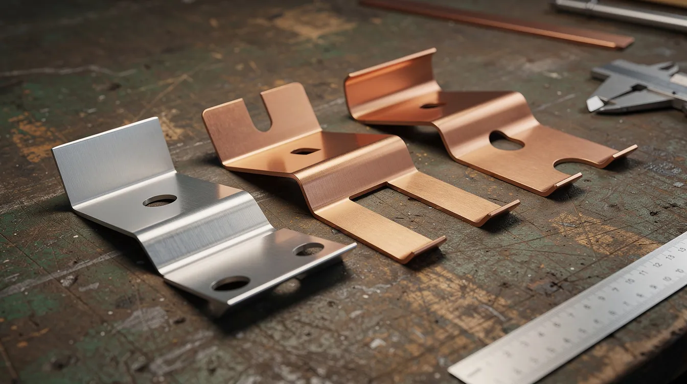
Copper and brass: High ductility permits tight radii, making these ideal for electrical connectors, bus bars, and RF shielding components. Copper typically allows radii down to 0.5–1× thickness.
Typical sheet thickness ranges for precision bending: 0.3–6 mm for stainless and aluminum, up to heavier gauges depending on brake press tonnage and bend length. Very thick plates or exotic alloys may require specialized tooling, larger bend radii, or alternative processes. Industry examples include 1.2–1.5 mm galvanized steel for HVAC enclosures, 2–3 mm 5052-H32 for automotive battery enclosures, and 0.8–1.0 mm 304 stainless for medical device housings.
From Flat Pattern to Bent Part: Process Flow at Anebon
Every bent part starts as a flat pattern and moves through a controlled sequence of operations. Here is how we handle it at Anebon.
-
Quotation and design review: The customer provides a 3D model (STEP/IGES) and ideally a 2D drawing with bend notes. Our engineers review bend allowance, bend deduction, feature-to-bend distances, and overall manufacturability. We flag issues like insufficient bend relief, unrealistic radii, or tolerance conflicts before cutting any material.
-
CAD/CAM and flat pattern development: Using modern sheet metal CAD modules with calibrated k factor tables, we generate the flat pattern and simulate the bend sequence. For complex parts with many flanges, the forming sequence determines whether the part can be bent accurately without tooling interference.
-
Cutting and preparation: Blanks are produced by CNC laser cutting or punching. Cutting tolerances are tighter than bending tolerances, so blanks are held to ±0.05–0.1 mm. Edges are deburred where required to prevent inconsistent bends. This is an automated process on our CNC machine lines.
-
Bending on CNC press brakes: Tooling (punch and die) is set up to match the required bend radius and die opening. The CNC controller manages ram depth, backgauge position, and bend sequence. In-process angle sensors verify the bend angle against the target, and operators measure critical dimensions with gauges or CMM on first articles.
-
Post-process and QA: Final inspection checks bend angles, flange lengths, hole positions relative to bends, and overall flatness. Parts are verified against customer drawings with documented inspection reports. Anebon is ISO 9001:2015 and ISO 14001:2015 certified, with documented bending procedures and inspection plans for every OEM project.
-
Production consistency: Once first articles are approved, process parameters (ram depth, backgauge positions, die setups) are locked into the CNC program. This allows us to maintain tight consistency across prototype, pilot run, and full production batches with minimal variation.
Bending vs. Other Fabrication Methods
Choosing the right process depends on part geometry, volume, tolerance requirements, and cost targets. Bending can produce parts quickly with minimal tooling compared to many alternatives.
-
Bending vs. welding/riveting: A single bent bracket eliminates weld joints, reducing potential leak paths, assembly labor, and alignment issues. For an electronics enclosure, forming four sides from one blank is faster and stronger than welding four separate flanges together. Bending reduces part weight without sacrificing strength because the formed flanges add stiffness geometrically.
-
Bending vs. machining from solid: For thin-walled parts like a medical device panel or automotive bracket, bending is far more material-efficient than milling from a solid block. Machining suits thicker blocks with deep pockets, threaded features, or very tight tolerance mating surfaces. Many parts combine both: bend the shell, then machine critical mounting features on a cnc machine.
-
Bending vs. stamping: For very high-volume, fixed designs, stamping with hard tooling delivers lower per-unit cost and faster cycle times. However, bending is less cost-effective for high-volume production runs only at extreme quantities. For prototyping and low-to-medium volume OEM runs (hundreds to low thousands), press brake bending wins on flexibility, lower tooling cost, and faster turnaround.
-
Anebon often combines bending with CNC machining, tapping, and surface finishing (anodizing, powder coating, plating) to deliver ready-to-assemble sheet metal precision parts. This integrated approach shortens supply chains and reduces handling between vendors.
Practical Tips for Design Engineers Working with Anebon
-
Define critical-to-function dimensions around bends clearly on your drawings: flange length, hole positions from bend lines, and mating surface flatness. This lets us set appropriate tolerances where they matter and relax them where they do not.
-
Send both 3D models and 2D drawings with bend lines, bend directions, desired bend radius, and material specs marked. Include any required bend relief or special bend sequence notes. Drawings should call out which surfaces are cosmetic.
-
Standardize bend radii and angles across your project family. Using the same inside radius and the same set of bend angles reduces tooling swaps and setup time, directly improving pricing and lead time.
-
Engage Anebon’s DFM review early. We can propose adjustments to bend radius, minimum flange length, or feature positions to avoid cracking, warping, or excessive springback before you finalize your design. Changes on a drawing cost nothing; changes on a production floor cost real money.
-
For bent parts with tight tolerances on hole-to-bend distances, consider adding the holes after bending via CNC drilling or punching. This avoids the tolerance stack-up that occurs when holes are cut in the flat pattern and then shifted by the bending process.
Sheet Bending Capabilities at Anebon Metal Products Limited
-
CNC hydraulic brake presses compatible with a range of die setups for air bending, bottom bending, and coining. Multi-axis backgauges enable complex bend sequences with high repeatability.
-
Maximum bending length up to 3000 mm; tonnage capacity up to 200 tons, suitable for thicker materials and long bends in mild steel, stainless, and aluminum. Bend length is limited by machine size and configuration, so we match equipment to each job’s requirements.
-
Supported materials: mild steel, carbon steel, galvanized steel, stainless steel (301, 304, 316), aluminum alloys (1050, 3003, 5052, 6061), copper, and brass. Sheet thickness from 0.3 mm to 6 mm standard; heavier gauges evaluated per project.
-
Fully integrated with in-house CNC machining (milling, turning, 5-axis), die casting, and surface treatments. Custom precision sheet metal bending parts can be delivered fully finished and assembly-ready, including hardware insertion, welding, and inspection documentation.
Case Examples: Bent Parts for OEM Applications
-
Aluminum electronics enclosure with louvers: A 1.5 mm 5052-H32 aluminum enclosure required eight 90° bends, integrated louver vents, and a painted exterior. The challenge was maintaining ±0.3 mm flange length tolerance across all bends while avoiding surface marks on the cosmetic face. Anebon used rotary bending dies for the final closing bends and protective film to keep the paint intact. The one-piece bent design replaced a previous three-piece welded assembly, cutting weight and assembly time.
-
Stainless steel Z-bend bracket for medical equipment: A 2 mm 304 stainless bracket with two Z-bends and tight flange length tolerance of ±0.15 mm. The high yield strength of stainless caused significant springback, and the short flanges were close to the minimum flange length limit. The team adjusted bend allowance values based on test coupons from the same material lot and used bottom bending with angle sensors to hold ±0.3° on each bend. The result was a bracket that fit its mating assembly without shimming.
-
Galvanized steel chassis for industrial robotics: A 3 mm galvanized sheet steel chassis with multiple bends, punched mounting holes, and bend relief cutouts around cable routing slots. Holes near the bends required careful placement beyond the 2.5–4× thickness zone to prevent deformation. Anebon optimized the flat pattern and bend sequence to avoid tooling interference on the deep U-channel profile. The finished chassis provided the structural integrity needed for a 25 kg payload robot arm mount.
How to Get a Sheet Bending Quote from Anebon
-
Prepare your files: 3D CAD models (STEP/IGES format), flat patterns if available, and 2D drawings with bend notes (bend radii, angles, tolerances, and bend directions). Include material grade, sheet thickness, estimated annual volume, and required surface finish.
-
Anebon provides DFM feedback on bend radius, bend allowance, bend deduction, and flange lengths to optimize cost and manufacturability before confirming the order. This review catches issues early and avoids delays during production.
-
We support projects from rapid prototypes (small batches in 5–10 business days) to full OEM production with scheduled shipments overseas. Whether you need five pieces for validation or five thousand per month, the quoting process is the same.
-
Contact Anebon via our website quote form or email to upload your drawings and start the quotation process. Our engineering team typically responds with preliminary DFM feedback and pricing within two business days.