Mastering Rapid Prototype Machines for Efficient Product Development
Rapid Prototype Machines: From Concept Models to Production-Ready Parts
Rapid prototype machines have transformed how engineers and product teams bring ideas to life. Instead of waiting months for tooling and samples, you can now move from a digital concept to a physical part in hours or days. This guide walks through the core technologies, applications, advantages, and selection criteria so you can put rapid prototype machines on the right path for your next project.
What Is a Rapid Prototype Machine?
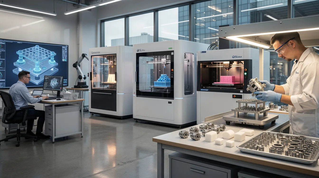
A rapid prototype machine is any digitally controlled tool-additive or subtractive-that converts a computer aided design file into a tangible physical part without requiring dedicated production tooling. The category spans a wider range of equipment than most engineers initially expect: FDM printers that extrude thermoplastic filament, SLA systems that cure resin with ultraviolet light, selective laser sintering machines that fuse powdered nylon, and CNC milling machines and lathes that cut metal or plastics from solid billets.
The roots of this technology go back decades. The Munz Process was developed in 1956 for 3D image reproduction, and Joseph Henry Condon developed UCDS at Bell Labs in the 1970s as an early computer-driven design system. Chuck Hull patented stereolithography in 1986, and rapid prototyping emerged in the late 1980s as a distinct discipline. The first FDM 3D printer was created in April 1992, making additive manufacturing accessible to a broader engineering audience.
At their core, these machines exist to validate form, fit, and function before you invest in expensive tooling like injection molding dies or die-casting molds. Additive manufacturing technologies build parts layer by layer-ideal for complex geometries-while subtractive methods like cnc machining remove material from raw stock, delivering superior mechanical strength and tight tolerances.
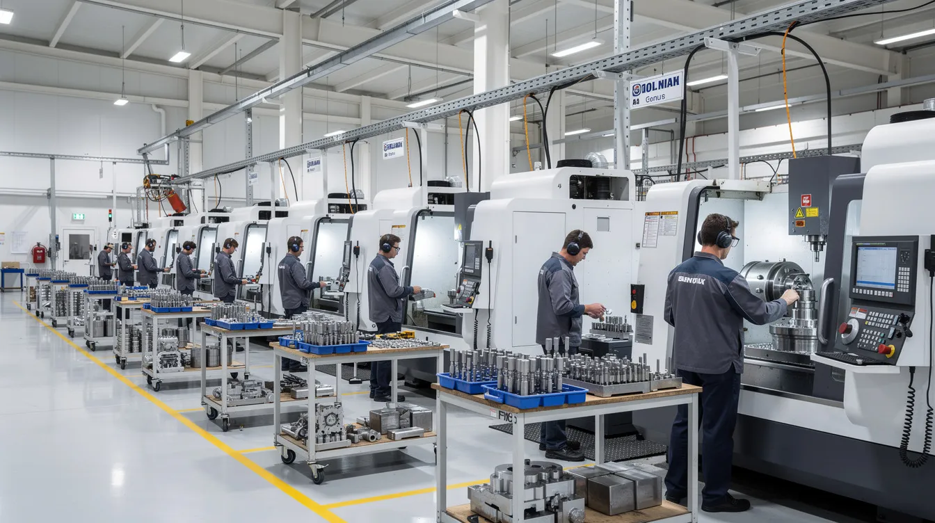
Anebon Metal Products Limited integrates both rapid prototyping and full-scale production under one roof, serving overseas OEMs from its Dongguan, Guangdong facility with precision CNC machining, die casting, and sheet metal fabrication.
How Rapid Prototype Machines Work in the Manufacturing Process
The digital workflow behind rapid prototyping is straightforward, but each step carries decisions that shape quality, cost, and speed.
-
CAD design – Engineers create or refine cad models defining geometry, tolerances, and material.
-
DFM feedback – The manufacturing partner reviews the design for manufacturability, flagging issues like unsupported overhangs, thin walls, or tool-access problems.
-
Process selection – Based on geometry, material, and performance needs, teams choose among 3d printing, CNC milling, sheet metal, or a hybrid approach.
-
Fabrication – The machine builds (additive) or cuts (subtractive) the physical prototype.
-
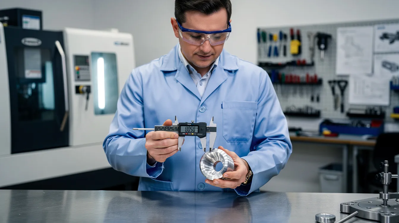
Post-processing and inspection – Support removal, surface finishing, heat treatment, and dimensional verification complete the cycle.
This rapid prototyping process reduces feedback loops from weeks to days. Design validation through prototyping helps identify flaws before mass production, and prototyping services help refine designs for manufacturability-catching geometry or tolerance issues while changes are still inexpensive.
Typical turnaround times vary: simple CNC metal parts often ship in 3–5 business days; complex multi-axis or finishing-intensive prototypes take 5–10 days; and 3d printing can deliver concept models in 1–3 days. Anebon’s ISO 9001:2015 quality system and tolerance capability as precise as ±0.002 mm allow prototypes to transition directly into pilot production without re-validation.
Types of Rapid Prototype Machines
No single machine fits every prototype. Engineers usually choose among several core technologies based on five criteria: geometry complexity, material (metal vs. plastics), surface finish, mechanical strength, and cost efficiency. Common rapid prototyping technologies include FDM, SLA, SLS, and CNC machining-each occupying a distinct performance and cost envelope.
Anebon primarily uses CNC machining, sheet metal fabrication, and die casting for high-precision metal and engineering-grade thermoplastics prototypes. When customers supply 3D-printed concept models, Anebon can interface those with machined components for hybrid assemblies.
FDM and Other 3D Printing Technologies
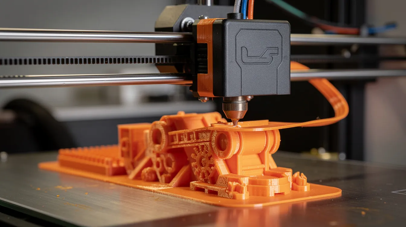
Fused deposition modeling is the most widely used 3d printing method and one of the earliest types of rapid prototyping available to product teams. An FDM 3d printer works by extruding thermoplastic filament-ABS, PLA, nylon-layer by layer, making it ideal for concept modeling and early form-and-fit checks. Setup is minimal, iteration is fast, and 3d printing technology is now accessible to any business, from startups to large OEMs.
Beyond FDM, other additive manufacturing technologies fill specific gaps:
-
Stereolithography (SLA) offers the highest resolution among 3d printing technologies and is up to 10X faster than FDM printing, producing smooth, high-detail parts for appearance validation.
-
Selective laser sintering fuses powdered nylon to produce strong, functional prototypes suitable for mechanical testing-performance approaching injection molding.
-
Metal additive manufacturing (DMLS/SLM) handles complex metal geometries but carries longer lead time (2–4 weeks including post-processing) and higher cost.
3D printing technologies include FDM, SLA, and SLS for rapid prototyping, and 3d printing allows for small-batch runs and custom solutions that traditional methods cannot match economically. The ability to quickly fabricate internal channels, lattice structures, and organic shapes gives additive a clear edge for creating models with complex internals.
However, limitations exist. Printed surfaces show visible layer lines (Ra 5–15 µm), mechanical properties are anisotropic, and dimensional accuracy falls short of precision cnc machining-especially when tight tolerances below ±0.05 mm are required.
CNC Machines for Rapid Prototyping
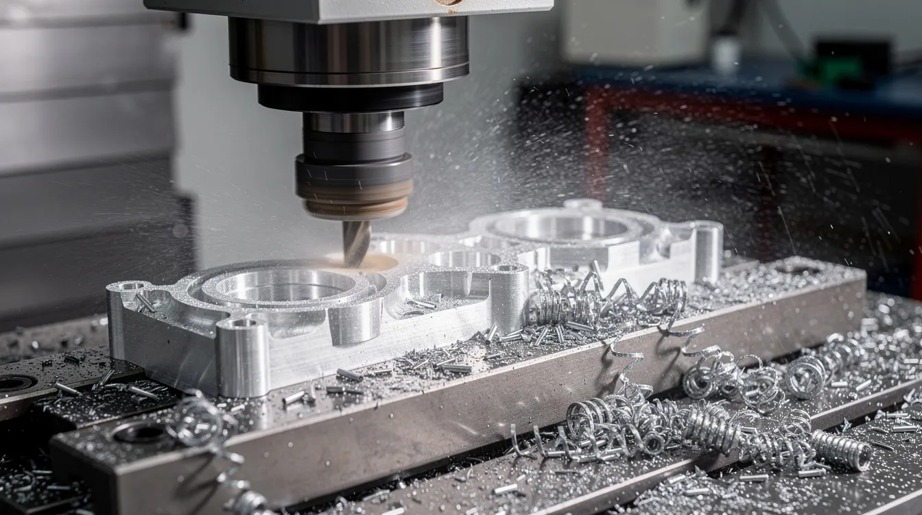
CNC machining is a subtractive rapid prototyping method for producing precise parts from solid billets of aluminum, stainless steel, titanium, or engineering plastics. Where additive builds up, CNC cuts away-and the result is a physical part with production-grade strength, surface finish, and dimensional fidelity.
Typical machines used in rapid prototyping work include:
|
Machine Type |
Best For |
Typical Tolerance |
|---|---|---|
|
3-axis CNC mill |
Flat and prismatic features |
±0.05 mm |
|
5-axis CNC machining center |
Complex contours, undercuts |
±0.01–0.02 mm |
|
CNC turning lathe |
Shafts, cylinders, spindles |
±0.02 mm |
|
High-speed spindle |
Fine features, thin walls |
±0.01 mm |
CNC rapid prototyping is critical when prototypes must closely match the finished product in material and performance-aerospace brackets in titanium, medical housings in 316L stainless, or automotive drivetrain components in hardened steel. Anebon’s CNC turning and milling capabilities deliver tolerances down to ±0.002 mm under optimized conditions, with surface finishes as low as Ra 0.8 µm after grinding or polishing.
CNC-machined prototypes frequently serve as reference parts when designing production tooling for injection molding or die casting-ensuring the final product matches the validated working prototype.
Specialized Equipment for Circuit Boards and Assemblies
Prototypes for electronics products involve more than mechanical parts. Circuit boards and housings must be validated together to confirm connector alignment, shielding effectiveness, and thermal management.
PCB prototypes can be produced using CNC milling of copper-clad boards or through conventional PCB fabrication services. Pick-and-place machines and reflow ovens assemble surface-mount components into functional electronic prototypes that engineers can test on the factory floor under real operating conditions.
Anebon often fabricates the mechanical side of these assemblies-metal enclosures, heat sinks, brackets, and precision frames-maintaining tight mechanical tolerances around circuit boards so connectors seat properly, EMI shields close without gaps, and thermal interfaces make full contact.
Key Applications of Rapid Prototype Machines
Rapid prototype machines serve different roles along the product lifecycle. Rapid prototyping supports enhanced visualization and testing of product designs, and prototypes allow teams to evaluate a product’s form, fit, and ergonomics early in development. Physical prototypes facilitate better teamwork and feedback from stakeholders, replacing abstract CAD reviews with tangible objects everyone can hold and assess.
The three main application stages are:
-
Proof-of-concept – Low-cost 3D prints or simple CNC parts verify size, ergonomics, and interfaces.
-
Engineering validation – High quality prototypes in production materials undergo mechanical, thermal, and environmental testing.
-
Pilot and bridge production – Short runs (tens to thousands of parts) using rapid prototype machines or rapid tooling fill demand while full-scale tooling is being built.
Automotive, Aerospace, and Industrial Machinery
These industries demand high reliability and often require both additive manufacturing and CNC machining within the same development program. Automotive teams use 3d printing for interior panels and dashboard components, then switch to CNC machining for metal brackets, gears, and powertrain parts before committing to injection molding or forging. Ford reduced prototype lead time from two weeks to overnight by integrating rapid prototyping into its design process, demonstrating the speed these tools can deliver.
Aerospace prototypes rely heavily on 5-axis CNC milling in aluminum or titanium for lightweight structural parts, with rapid iteration to eliminate design flaws before certification testing. Industrial machinery and robotics teams use rapid prototype machines to test custom grippers, linear stages, and sensor mounts under load in real factory conditions-catching failures that simulations miss.
Anebon supports these sectors with tight-tolerance CNC parts, sheet metal frames, and die-cast housings during prototype and low-volume phases.
Consumer Electronics and Medical Devices
Appearance, ergonomics, and compact packaging drive the product design process in consumer electronics and medical devices. Designers use 3d printing for fast concept modeling of handheld devices, wearables, and medical instruments-checking button placement, display visibility, and grip comfort before cutting metal.
The transition to metal prototypes follows quickly. CNC-machined aluminum, stainless steel, or high-performance plastics produce high fidelity prototypes for drop tests, sterilization trials, and regulatory validation (IEC, FDA). Examples include smartphone frames, wearable device enclosures, diagnostic equipment housings, and precision circuit board carriers.
Anebon produces cosmetic-grade surfaces and applies surface treatments-anodizing, polishing, powder coating-on prototypes to simulate final production quality, helping product teams present convincing samples to stakeholders and certification bodies.
Advantages and Limitations of Rapid Prototype Machines
Rapid prototyping is powerful, but it works best with a clear strategy that balances speed, cost, and technical risk. Understanding the benefits of rapid prototyping alongside its constraints helps engineers avoid costly surprises.
Key advantages:
-
Accelerated design iterations-iterate quickly across multiple variants in parallel
-
Early detection of design flaws before committing to production tooling
-
Rapid prototyping can cut production costs significantly by preventing premature tooling investments (a single injection mold can cost $10,000–$100,000+)
-
Early design iterations through rapid prototyping reduce risks and cost overruns
-
Rapid prototyping speeds up learning and problem-solving during product development
-
Custom molds, jigs, and fixtures can be printed to reduce production downtime
-
3D printing allows for small-batch runs that let manufacturers test market demand before scaling
Key limitations:
-
Initial costs of rapid prototyping can be expensive due to technology investments and per-part pricing at low volumes
-
Rapid prototyping can limit the range of materials used-not every production alloy or polymer has a printable equivalent
-
Prototypes may lack accuracy and quality assurance compared to production quality parts, especially with some additive processes
-
Drawing conclusions from a single physical prototype risks tunnel vision; multiple builds and inspection are often necessary
Anebon mitigates many of these limitations by combining additive concept models with high-accuracy CNC machining and real-time DFM feedback, ensuring prototypes stay aligned with manufacturable designs.
Cost Efficiency and Time-to-Market Impact
Rapid prototype machines influence both direct costs (per-part) and indirect costs (engineering time, tooling rework, launch delays). The iterative process of frequent CAD adjustments validated by physical models compresses engineering change cycles from weeks to days. 3D printing can create prototypes in a matter of hours, and rapid prototyping allows movement from digital concepts to physical models within hours or days-helping teams get to market faster.
Cost efficiency depends heavily on context:
|
Scenario |
Most Cost Effective Approach |
|---|---|
|
Multiple early concept variants |
FDM/SLA 3D printing ($10–$150/part) |
|
Functional metal prototypes (1–10 units) |
CNC aluminum machining ($80–$300/part) |
|
Bridge production (50–500 units) |
CNC machining or rapid tooling |
|
Complex internal geometries |
SLS or metal additive manufacturing |
It reduces production costs for overall product development by catching problems early-before expensive tooling is cut. For functional testing and bridge production, CNC machining or rapid tooling may offer better long-term cost efficiency due to durable materials and consistent tolerances. Anebon helps customers choose the most economical path-3D printing, CNC machining, or a hybrid approach-based on quantity, material, and performance targets.
Choosing the Right Rapid Prototype Machine and Partner
Selecting the right rapid prototyping technology and manufacturing partner is as important as the design itself. The decision framework breaks down by development stage:
-
Looks-like prototypes (appearance, ergonomics) → SLA or FDM 3D printing, then CNC for cosmetic metal parts
-
Works-like prototypes (function, durability) → CNC machining in production materials, SLS for load-bearing plastics
-
Manufacturability validation (DFM, tolerances, assembly) → CNC or die-cast prototypes that mirror the production process
Beyond technology, the right partner provides design and engineering support: DFM feedback that flags problems before you build, material selection advice matched to your end-use environment, and tolerance stack-up analysis that prevents assembly failures. Rapid prototyping services should feel like an extension of your engineering team, not just a machine shop filling requests.
How Anebon Supports Your Rapid Prototyping to Production Journey
Since 2010, Anebon Metal Products Limited has served overseas OEMs across aerospace, medical, automotive, electronics, and robotics as a B2B precision manufacturer. Engineers rely on Anebon to create prototypes and produce parts across a wider range of processes than most single-source shops can offer.
Core capabilities relevant to rapid prototype machines:
-
CNC milling and turning (3-axis through 5-axis)
-
High-pressure die casting for aluminum and zinc
-
Sheet metal fabrication (laser cutting, bending, punching)
-
Surface treatments: anodizing, polishing, plating, powder coating
-
Tolerances as precise as ±0.002 mm on stabilized materials
Anebon holds ISO 9001:2015 and ISO 14001:2015 certifications, with in-process inspection and final quality reports accompanying every prototype and production batch. The typical engagement is simple: submit your CAD files and requirements, receive DFM feedback and a quotation, approve the prototype plan, then iterate toward production-ready designs-all with a single, accountable partner.
Whether you need a single physical model to validate a concept or a bridge production run of hundreds of production quality parts, the goal is the same: compress your development timeline, control cost, and reach production with confidence. Request a quote or contact Anebon’s engineering team to start your next rapid prototyping project and put your product development on the right path.