Mastering CNC Programming: Essential Tips and Techniques for Success
CNC Programming: A Practical Guide for OEM Engineers and Machinists
Introduction to CNC Programming
CNC programming is the process of creating coded instructions for automated machine tools, turning digital designs into physical components with repeatable accuracy. In modern manufacturing, computer numerical control programming serves as the bridge between a CAD model on screen and a finished part in your hands. Every axis position, feed rate, spindle speed, and tool change is governed by precise instructions written in g code and m codes-the programming language that cnc equipment understands.
Why does this matter for OEMs? In aerospace, medical devices, automotive, electronics, and robotics, cnc programming ensures high precision and repeatability in manufacturing. Tolerances of ±0.005 mm or tighter, complex multi-axis geometries, and certified traceability are not optional-they are baseline requirements. CNC programming automates complex manufacturing tasks efficiently, allowing shops to scale from prototype to mass production without sacrificing quality.
At Anebon Metal Products Limited, we have been delivering precision CNC machining from our Dongguan facility since 2010, holding ISO 9001:2015 and ISO 14001:2015 certifications with tolerances as tight as ±0.002 mm. This article draws on our production-floor experience to give you practical guidance on the entire machining process. Consider a real example: machining an aluminum medical device housing with 5-axis milling. Well-optimized cnc programming reduced cycle time by over 25%, eliminated two setup changes, and brought scrap rates near zero-all because the programming process was handled correctly from the start.
What Is CNC Programming and How Does It Control a CNC Machine?
CNC programming is the process of composing instructions-primarily g code and m codes-that tell a cnc machine exactly how to move, cut, drill, or turn raw material into a finished part. It is the actionable layer where digital geometry becomes physical reality.
-
CNC programs establish a chain from cad models through cam software to the machine controller. They define axis positions within a cartesian coordinate system, feed rate, spindle speed, and which cutting tools to use at each step.
-
Tool movements are described using motion codes: rapid moves, linear feeds, circular arcs, and canned cycles. These detailed instructions appear as specific cnc codes on mills, lathes, and 5-axis machines.
-
CNC programming uses g-code to control tool movements, while m-code manages auxiliary functions like spindle control, coolant, and tool changes. G-code and m-code are essential for cnc programming regardless of machine type.
-
The cnc programmer writes or configures the nc program; the machine operator loads stock, fixtures, and tools, then proves out the first part. In OEM workflows, design engineers often contribute DFM feedback before programming begins.
-
Common cnc machine types in OEM production include 3-axis and 5-axis machining centers, CNC turning centers, and mill-turn machines. Program structure differs by machine type-a turning program uses two primary axes and canned roughing cycles, while a 5-axis program must manage tool orientation and collision avoidance across additional rotary axes.
CNC programming automates machine tools for precision tasks and streamlines workflows managing complex operations that would be impractical to perform manually.
Types of Computer Numerical Control Programming
Different programming methods exist depending on part complexity, production volume, and operator skill level. Three main types of CNC programming exist: manual, CAM, and conversational. Understanding the types of cnc programming helps you choose the right approach for each job.
Manual CNC Programming
Manual programming means writing raw g code and m codes line by line, often directly at the control or in a text editor. Manual CNC programming is the oldest and most challenging method, but it remains relevant.
-
It is still used for simple turning profiles, basic pocketing, quick one-off modifications, or when cnc programming software is not available.
-
Required skills include understanding coordinate systems, tool radius compensation, cutter tool paths, and safe retract moves-all without graphical interface support. A good cnc programmer can visualize the machining operation mentally.
-
Pros: maximum control over every line, no software cost, very fast for simple tasks.
-
Cons: time-consuming, error-prone for complex operations, and impractical for multi-axis work. The learning curve is steep for beginners, who should start with simple projects to build basic knowledge.
-
Even in CAM-centric shops, Anebon programmers maintain manual programming skills for quick edits, on-the-fly corrections, and manual adjustments during prove-out.
CAM CNC Programming
Computer aided manufacturing through cam software is the standard approach for complex parts and production work. CAM programming converts CAD designs into cnc machine instructions, and it dominates 2024–2026 industrial practice for overseas OEMs.
-
Cam software reads cad models, lets the programmer choose strategies, select the appropriate tool, set cutting parameters, and then posts out machine-specific cnc programs. CAM software translates CAD models into tool paths and generates the required g code automatically.
-
Popular cnc programming software includes Mastercam and Fusion 360. Autodesk Fusion 360 supports 2D, 2.5D, and 5-axis machining solutions, making it accessible across machine types.
-
CAM excels at multi-axis machining, complex operations, and toolpath optimization that would be impractical to code by hand. CNC programming software converts CAD files into machine-readable code, and cam software automates the creation of cnc programming code.
-
Integrated cad and cam software reduces data transfer errors and supports revision control. Anebon uses integrated CAD/CAM for both prototypes and production runs.
-
Simulation software built into CAM catches collisions, over-travel, and gouging before metal is cut, helping avoid scrap and machine damage.
-
CAM still requires human judgment for tool selection, workholding strategy, and verifying the program suits the cnc operator and machine type. Computer software handles computation; skilled programmers handle decisions.
Conversational and Parametric Programming
These programming methods fill specific niches in real production environments.
-
Conversational programming is menu-driven programming at the machine, where the operator fills in forms for pockets, holes, and simple contours via a graphical interface. Systems like Mazatrol and Haas conversational modes make this accessible. Conversational programming is the easiest type for beginners to learn.
-
It is ideal for quick, simple parts, fixtures, or repairs, but is limited for 5-axis or very tight-tolerance work.
-
Parametric (macro) programming uses variables, formulas, and logic to create families of parts or adaptive cycles. For example, on a turning center you can program a generic shaft with macro variables for overall length, diameter, and shoulder depth-one template yields multiple variants without rewriting the entire program.
-
Anebon applies macro logic for recurring OEM projects where dimensions change but the setup and cnc process remain similar, accelerating turnaround.
Core CNC Codes and Programming Concepts
While syntax varies slightly between controllers from Fanuc, Siemens, and Heidenhain, the fundamental concepts are universal. G-code is the primary language used in cnc programming, and understanding how codes interact is critical to avoiding crashes or scrap.
The main groups include motion g-codes, modal states, m codes that control auxiliary functions, coordinate systems (G54–G59 work offsets), and feed and speed commands. OEM expectations for documentation include clearly commented programs, consistent structure, and standardized headers listing material, tooling, and version. Anebon’s internal programming standards ensure repeatability across multiple cnc machines and shifts.
G-Codes, M-Codes, and Coordinate Modes
G-codes are preparatory commands that control motion and path type. G-codes control tool movements while m codes manage machine functions-two complementary systems that together define every machining operation.
-
G00 and G01 are common g codes for positioning: G00 handles rapid traverse, G01 handles linear cutting feeds. G02 and G03 command circular interpolation for arcs.
-
M codes control auxiliary functions including spindle on/off (M03/M04/M05), coolant (M08/M07), tool change (M06), and program end (M30). M codes control machine functions that support the cutting process.
-
Absolute positioning (G90) vs incremental positioning (G91) determines how coordinates are interpreted. A mistake here-switching modes without realizing it-is one of the most common causes of collisions and scrap. Understanding this distinction is essential for any cnc programmer.
-
Plane selection codes (G17, G18, G19) determine the active plane for circular interpolation, which matters when programming arcs on different faces of a part.
-
Best practice: comment key lines, group related codes logically, and maintain a consistent start and end sequence in every program. For a deeper reference, see Anebon’s guide to essential CNC programming formulas.
Feed Rates, Speeds, and Compensation
Feed rate (F) controls how fast the tool moves through material. The f code value directly impacts surface finish, tool wear, and cycle time. Spindle speed (S) sets rotation speed and must be matched to material and tool diameter.
-
On mills, feed rate is typically programmed in mm/min; on lathes, mm/rev. The machine operator must verify modes before running. Understanding cutting speed and feed speed relationships prevents premature tool failure.
-
Tool length compensation (G43) and tool diameter compensation (G41/G42) allow the programmer to define the ideal cutter path and let the controller adjust for actual tool dimensions. This means tool changes do not require rewriting the path.
-
Programmers must consider material when setting cutting parameters. Aluminum allows higher speeds but demands good chip evacuation; titanium requires slower feeds and lighter cuts; stainless steel needs moderate speeds with careful heat management; plastics require low heat to avoid melting.
-
Anebon follows material-specific parameter libraries refined from over fifteen years of production data to shorten setup and reduce risk for OEM clients.
Step-by-Step: How to Program a CNC Machine from CAD Model to Finished Part
While details vary by shop and machine type, most projects follow a consistent workflow from computer aided design to finished component. Here is the general process design that applies across the manufacturing industry.
Consider a concrete scenario: programming a 5-axis aluminum aerospace bracket in early 2025. At each step, decisions determine whether the part comes off the machine right the first time.
From CAD Models to Toolpaths
-
Import solid cad models (STEP, IGES, or native CAD formats) into your cam programming platform. Clean up geometry if surfaces are missing or edges are malformed.
-
Set stock size, zero point (work coordinate system, typically G54), and fixture orientation so that simulations match real cnc machines on the shop floor.
-
Choose machining strategies based on machine type and part geometry. For the aerospace bracket, the programmer must decide between 3+2 indexed positioning versus full simultaneous 5-axis machining to reach undercut features.
-
Tool selection follows: end mills, face mills, drills, taps-each chosen as the appropriate tool for the material, reach, and required surface finish. The right cutting tools make the difference between a clean part and scrap.
-
Anebon’s engineers often suggest DFM tweaks at this stage-fillet radii adjustments, wall thickness changes, improved tool access-to reduce cycle time and risk before finalizing cnc programs.
Simulation, Verification, and Program Transfer
-
CAM simulation checks tool movements against cad models to catch over-travel, collisions, and unmachined features before any material is cut. This is where simulation software earns its keep.
-
Machine simulation profiles mirror real cnc machines, including travel limits and rotary axes, for more accurate verification. This is especially critical for complex 5-axis parts where collisions between the spindle head and fixtures are a real risk.
-
Post-processing generates machine-specific g code and m codes for the target controller (FANUC, Siemens, Heidenhain). The post-processor must match the control dialect exactly.
-
Final cnc programs are transferred to machines via network, USB, or DNC and reviewed by the cnc operator before the first run.
-
Anebon’s internal approval steps include program review, setup sheet creation, tool list verification, and first-article inspection before releasing any job to full production. CNC programming reduces human errors in production through these systematic checks.
CNC Programming for Milling, Turning, and 5-Axis Machining
Core principles are shared across machine types, but programming strategies differ for milling, turning, and multi-axis work. CNC programming is essential for modern industrial production across all these platforms.
-
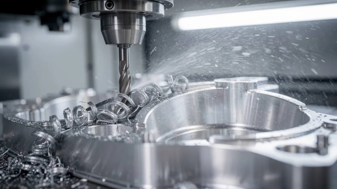
In cnc milling, milling uses rotating cutting tools to remove material from a stationary block. Toolpaths are structured layer by layer: roughing removes bulk material, semi-finishing leaves consistent stock, and finishing passes achieve final geometry and surface quality. Routing and drilling involve automated routing and precise high speed machining for holes and patterns.
-
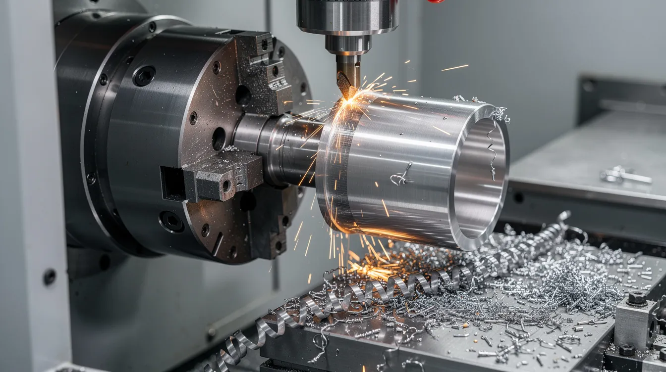
In turning, turning uses a lathe to rotate material while shaping it with a cutting tool. Programs work primarily in two axes, using canned cycles for roughing, finishing, drilling, and threading. Bar feeder logic and cycle time calculations enter the programs for production runs.
-
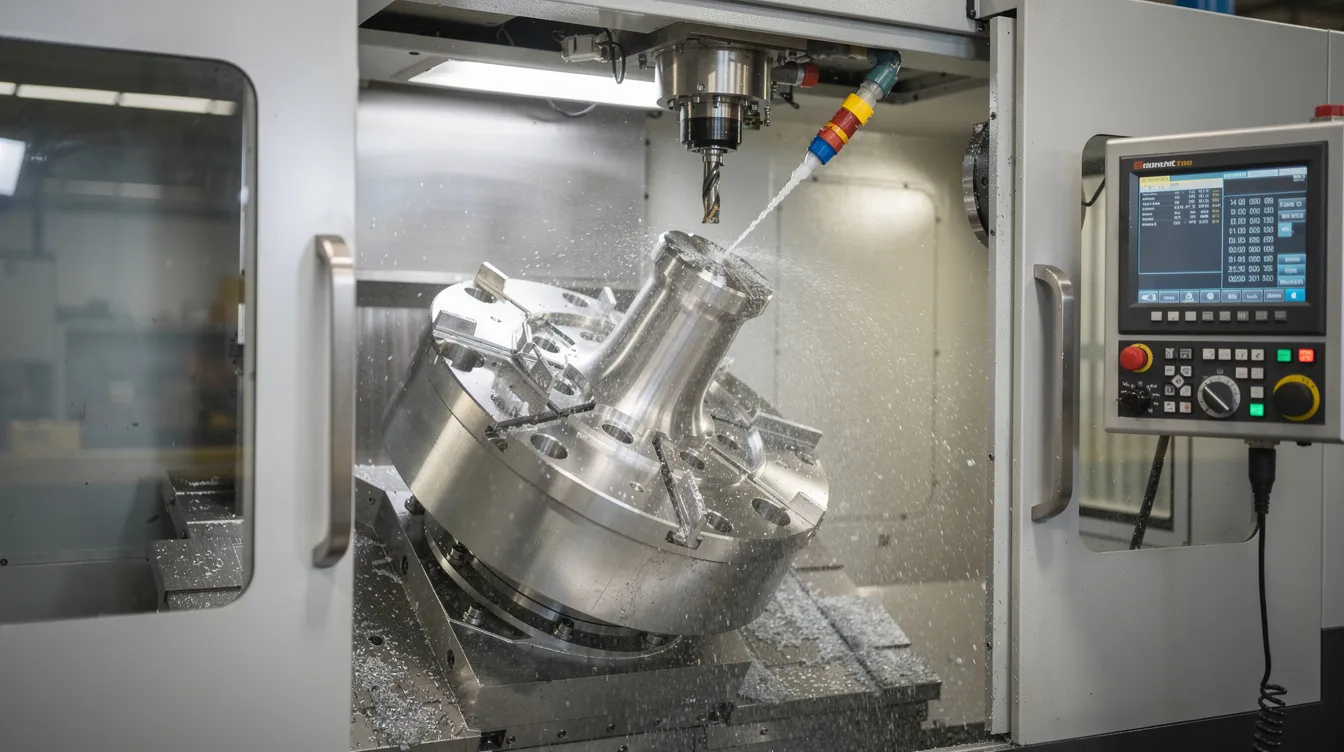
For 5-axis cnc machining, programming handles simultaneous or 3+2 indexed tool orientation. Collision avoidance, managing tool tilt and yaw, and kinematic constraints make CAM essentially mandatory. Manual programming of simultaneous 5-axis paths is not feasible for real production.
-
Anebon operates multi-axis machining centers that allow many features to be completed in a single setup, which reduces accumulated error for OEM components and cuts lead time.
Programming Strategies for Complex Operations
-
High speed machining strategies like constant engagement and trochoidal milling keep tool load consistent, especially in hard materials. These strategies impact feed rate, step-over, and tool life, enabling the machine to perform tasks that conventional approaches cannot sustain.
-
Multi-operation programs combining milling and turning on mill-turn machines require careful sequencing of tool changes and m codes. Spindle direction, coolant control, and coordinate system swaps must be programmed precisely.
-
Fixture and workholding considerations are embedded in every program: clearance moves, safe retract heights, and verification that tool movements will not hit clamps or vises. Misjudged paths cause expensive crashes.
-
Complex operations benefit from templated processes and proven subprograms. These reduce programming time and risk by building on validated milling strategies rather than starting from scratch.
-
Anebon maintains a library of validated cycles and templates for recurring aerospace, medical, and electronics parts, accelerating future orders for OEM partners. When dimensions change but the process is similar, computer control through parametric templates handles the variation.
Best Practices, Quality, and Partnering with Anebon for CNC Programming
Effective cnc machine programming combines computer aided manufacturing tools, shop-floor feedback, and robust quality processes. CNC programming ensures high precision in manufacturing processes, but only when the surrounding systems support it. CNC programming allows for consistent quality in manufactured parts when best practices are followed systematically. CNC machines can operate automatically allowing for continuous production cycles, making modern manufacturing processes efficient and scalable.
Here are the practices that separate reliable production from costly guesswork:
-
Standardize program structure: consistent naming, headers listing material and version, documented tool lists, and standardized offsets across all cnc equipment.
-
Use version control for CAM files, post-processors, and final g code. According to a 2026 industry survey, 62% of shops still use paper-based program verification, and 41% of nonconformities stemmed from mismatched code versions. Digital verification eliminates this.
-
Archive proven cnc programs for traceability and future reorders. When production ramps, you need the exact program that made good parts last time.
-
In-process measurement via probing cycles and SPC feeds back into program refinements. Final inspection data from multi-stage inspection protocols helps tighten tolerances and reduce scrap over time. This is how you maintain ±0.002 dimensional stability across production runs.
-
Anebon’s quality framework (ISO 9001:2015, ISO 14001:2015, advanced inspection equipment) ties directly to programming validation and sign-off. Industry certifications like NIMS certification are recognized in the cnc programming industry and complement shop-level quality systems. Online courses and tutorials are available for learning cnc programming fundamentals, but production-level skill comes from floor experience.
CNC programming is essential across modern manufacturing processes, from additive manufacturing post-processing to traditional subtractive machining. When should OEMs consider outsourcing? When facing tight deadlines, complex tasks requiring 5-axis work, limited internal machine capacity, or ultra-tight tolerances that demand proven process capability-these are the scenarios where a partner like Anebon adds the most value. We handle the complex tasks so your team can focus on design and assembly.
Send your cad models, technical drawings, and specifications to Anebon Metal Products Limited for DFM feedback, cnc programming support, rapid prototyping, and scalable production quoting. Whether you need a single prototype or ongoing mass production, our team of skilled programmers and engineers is ready to help you machine parts right the first time.