Mastering CNC Machining: Techniques for Precision and Efficiency
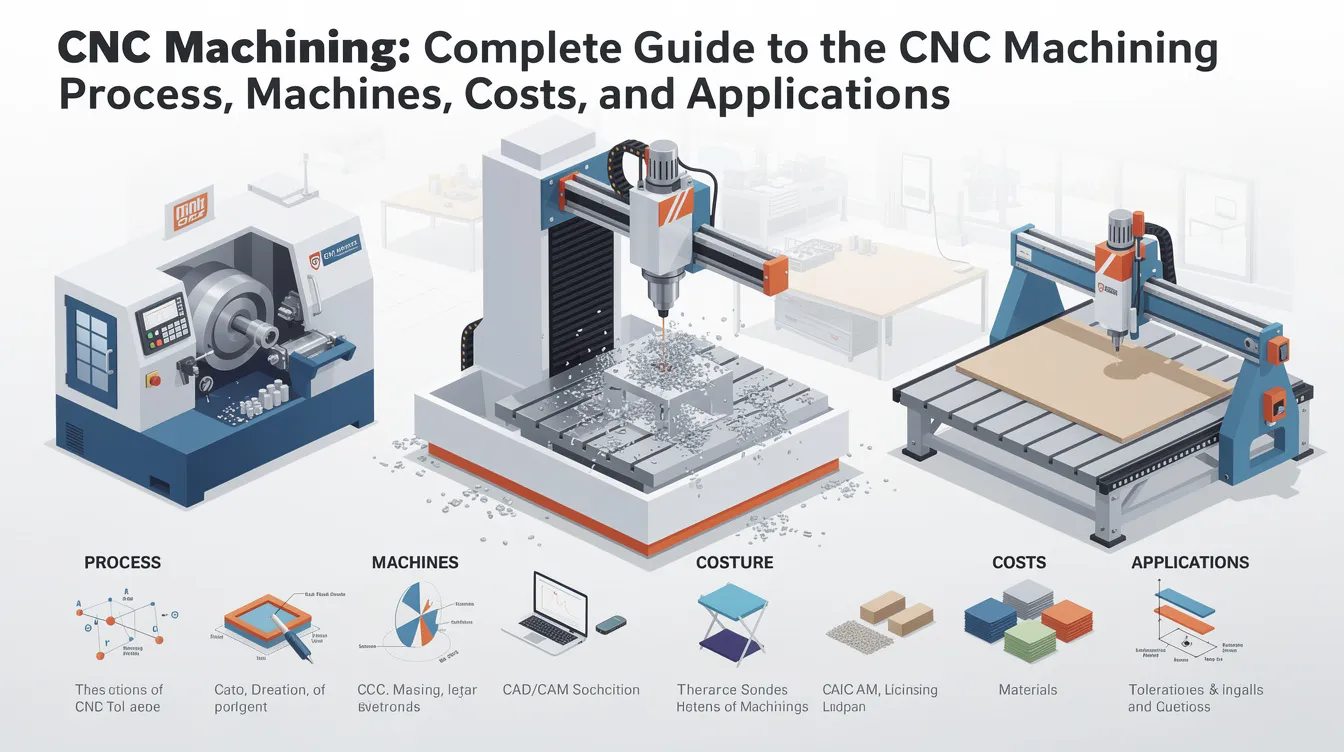
CNC Machining: Complete Guide to the CNC Machining Process, Machines, Costs, and Applications
CNC machining uses computer software to control machinery that removes material from a solid block of metal or plastic, producing finished parts with tolerances as tight as ±0.001 inches or better. This guide covers every stage of the CNC machining process, from CAD design through final inspection, and explains the machines, materials, costs, and applications that matter to engineers and buyers sourcing precision parts.
What Is CNC Machining?
Computer numerical control machining is a subtractive manufacturing process in which a CNC machine follows pre-programmed computer software instructions to move a cutting tool along defined paths, removing material from stock to create a finished part. The process starts with a computer aided design (CAD) model, which is translated into G code through computer aided manufacturing (CAM) software.
CNC machining makes parts from metals, plastics, and composites with extreme precision and repeatability. Here is what sets this manufacturing technology apart:
-
Precision and tolerances. CNC machines can achieve tolerances of ±0.001 inches or better. Anebon Metal Products Limited holds a standard machining tolerance of ±0.01 mm, with ±0.002 mm achievable on critical features after design-for-manufacturability review.
-
Repeatability. CNC machines provide excellent repeatability for producing identical parts. A validated program can produce tens of thousands of identical parts without dimensional drift, because closed-loop servo motors and encoders correct positioning errors in real time.
-
Prototypes through production. CNC machining can be used for both prototypes and high-volume production. A single setup can produce one piece for validation or thousands for assembly lines.
-
Reduced human error. The CNC machining process is fully automated and reduces human error during production. Once the program is proven, operator intervention is limited to loading stock and monitoring the run.
-
CNC vs. manual machining. Conventional machining relies on manual control of handwheels and levers; CNC replaces that with digital computers and servo motors. CNC machining offers higher precision and accuracy than manual machining and requires fewer skilled labor hours for repetitive work.
-
CNC vs. 3D printing. Additive processes build parts layer by layer; CNC machining removes material. CNC produces stronger mechanical properties in solid metals, tighter tolerances, and better surface finishes. CNC technology can produce complex shapes that are difficult to create manually, while additive has advantages for internal lattice structures and low-volume polymer parts.
How Do CNC Machines Work?
Understanding how CNC machines work requires following the data path from design file to finished cut. CNC machines use computer software to control machinery through a sequence of coordinated steps.
-
CAD model import. The engineer creates a 2D or 3D model using CAD software such as SolidWorks, CATIA, Siemens NX, or Autodesk Inventor. Files are exported as STEP, IGES, or Parasolid formats.
-
CAM programming. CAM software (Mastercam, PowerMill, Fusion 360) reads the CAD geometry, generates roughing and finishing toolpaths, runs collision simulations, and outputs G code. CAM programming translates CAD designs into numerical control code for machines.
-
CNC system components. The machine control unit (MCU) interprets G code and sends motion commands to servo motors or stepper motors. Ball screws and linear rails convert rotary motor motion into linear tool movement. Feedback encoders on each axis report position back to the controller, forming a closed-loop CNC system that corrects errors within ±0.005 mm.
-
Coordinate systems. Most CNC machines operate in Cartesian coordinates with three linear axes: X (left-right), Y (front-back), and Z (up-down). Rotational axes (A, B, C) rotate around X, Y, and Z respectively. The CNC operator sets a work zero point (G54 offset) so all programmed coordinates reference the actual part location.
-
Workholding and tooling. Vises, chucks, and custom fixtures secure the workpiece. An automatic tool changer swaps between multiple tools (drills, end mills, reamers) without manual intervention.
-
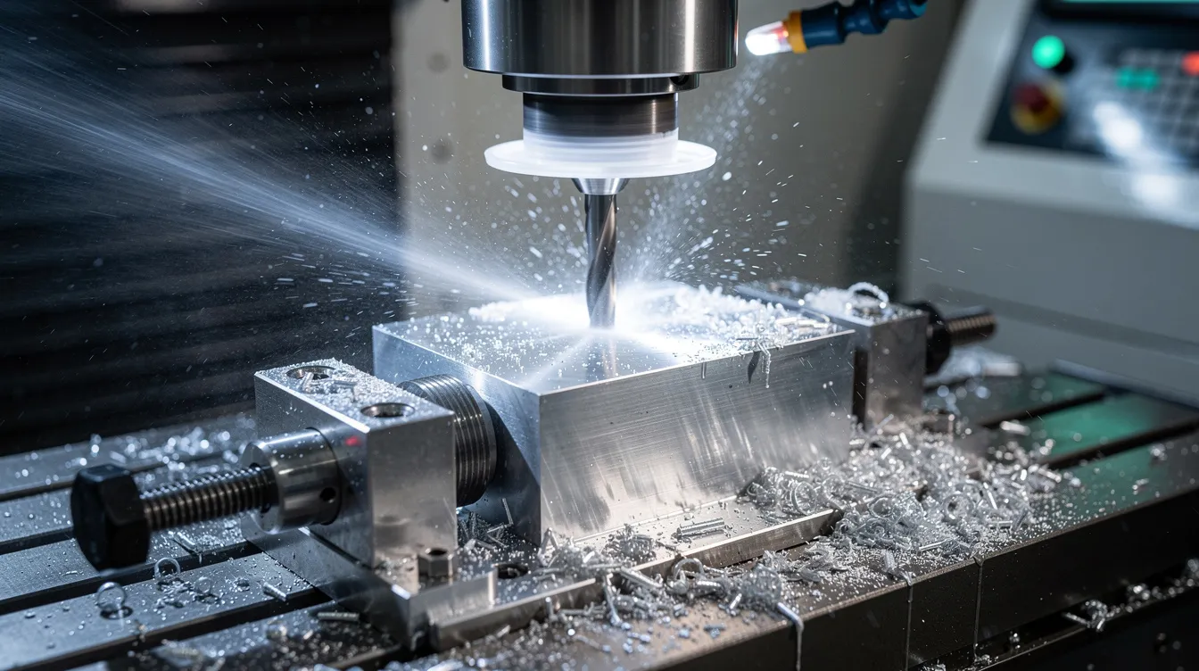
Cutting and feedback. During machining, the spindle rotates the cutting tool (in milling) or the workpiece (in turning). Coolant flushes chips and manages heat. In-machine probing can verify dimensions mid-cycle, catching deviations before they become scrap.
Core CNC Manufacturing Processes
Most CNC manufacturing work falls into four core machining techniques: milling, turning, drilling, and grinding. Each machining process suits a different part geometry and tolerance requirement. For a deeper look, see our guide to CNC machining techniques and applications.
-
CNC milling. A rotating cutting tool removes material as it moves across the workpiece. CNC mills typically operate on a three-axis system (X, Y, Z); 5-axis mills add two rotational axes for undercuts and compound curves. Milling creates pockets, slots, flat surfaces, and 3D contours. Typical milling tolerances range from ±0.01 mm to ±0.05 mm depending on material and machine rigidity. Face milling produces flat reference surfaces; profile milling traces complex shapes.
-
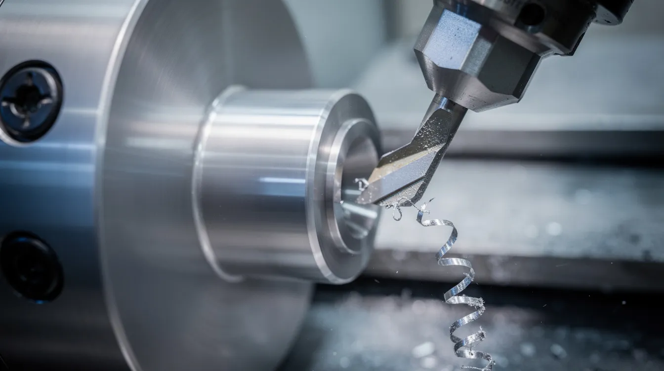
CNC turning. CNC lathes are used for producing cylindrical parts. The raw stock rotates in a chuck while the cutting tool moves linearly to remove material. Operations include facing, grooving, threading, and boring. Turning is the go-to for shafts, bushings, fittings, and any part with rotational symmetry. Concentricity on aerospace and medical turned parts often needs to stay within single-digit microns.
-
CNC drilling. Drilling on a milling machine or dedicated drilling center produces accurate holes, hole patterns, counterbores, and tapped threads. Deep-hole drilling (depth-to-diameter ratios above 10:1) requires peck cycles and through-tool coolant to evacuate chips.
-
CNC grinding. Grinding uses an abrasive wheel to finish hardened or heat-treated surfaces. It achieves tolerances of ±0.001 mm and surface finishes between Ra 0.2 and Ra 1.6 µm. Grinding typically follows roughing on a milling machine or lathe machine and is common for mold components, die inserts, and bearing surfaces.
CNC machining can produce complex shapes with high accuracy across all four processes, and minimizes material waste through optimized toolpathing generated in CAM software.
Types of CNC Machines
This section categorizes the common types of CNC machines found in modern shops, including at Anebon Metal Products Limited. Each machine type suits different part geometries, volumes, and complexity levels. For additional context, read about CNC machining centers.
-
Vertical machining centers (VMCs). The spindle is oriented vertically. Axis travels on small-to-medium VMCs range from 300 to 800 mm in X and Y, 300 to 500 mm in Z. Spindle speeds of 5,000 to 12,000 rpm handle aluminum and steel. Choose VMCs for flat parts, pockets, and prismatic shapes where setup simplicity and lower CNC equipment cost matter.
-
Horizontal machining centers (HMCs). The horizontal spindle lets chips fall away by gravity, improving chip evacuation in deep-pocket work. Pallet changers allow one part to be machined while the next is loaded. HMCs excel when throughput and multi-side access without re-fixturing are priorities.
-
CNC lathes and turning centers. Bar-fed CNC lathes run unattended for long production cycles of turned parts. Live-tool (mill-turn) machines mount driven tools on the turret, combining milling and turning in one setup. This eliminates a second machine and a second alignment, reducing error.
-
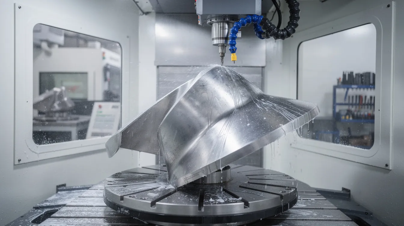
5-axis machining centers. Simultaneous 5-axis machines move all five axes at once; 3+2 machines lock two rotational axes and cut with three linear axes. Multi-axis CNC machines can achieve intricate 3D geometries needed for turbine blades, orthopedic implants, and mold cavities.
-
CNC routers. Designed for plastics, wood, foam, and soft metals, CNC routers have large work envelopes and high spindle speeds but lower rigidity than milling machines.
-
Electrical discharge machining (EDM). Electric discharge machines shape hard metals with electrical sparks, eroding material without mechanical contact. Wire EDM cuts profiles with a thin wire electrode; sinker EDM plunges a shaped electrode into the workpiece. Both handle hardened tool steels that would destroy conventional cutting tools. This is also called spark machining.
-
Laser cutting, waterjet, and plasma. Laser cutting slices thin sheet metals with a focused beam. Water jet cutters use high-pressure water (sometimes mixed with abrasive garnet) to cut hard materials without heat distortion. CNC plasma cutters use a plasma torch to cut metal materials, typically carbon steel and stainless steel plate. These CNC tools complement milling and turning for sheet and plate work.
Axes in CNC Machining: From 3-Axis to 5-Axis
An “axis” in CNC machining is a direction of controlled motion. Linear axes (X, Y, Z) move the tool or workpiece in straight lines; rotational axes (A, B, C) rotate around those lines. More axes mean fewer setups and access to more surfaces. Multi axis machining is a defining capability of modern CNC machines.
-
3-axis machining. The tool moves in X, Y, and Z. Suitable for brackets, cover plates, electronic housings, and other prismatic components. Most CNC machines in production shops are 3-axis. Tolerances of ±0.01 to ±0.05 mm are standard for these parts.
-
4-axis machining. A rotary axis (typically A) indexes or continuously rotates the workpiece. This allows machining around a cylinder or accessing multiple faces in one clamping. Gear blanks, flanges with circumferential features, and indexing operations all benefit.
-
5-axis machining. Two rotational axes tilt and rotate the part or tool head so the cutting tool can approach the workpiece from nearly any angle. Simultaneous 5-axis cutting traces compound-curved surfaces in a single pass; 3+2 positioning locks the rotary axes, then machines with three linear axes. Turbine blades, medical implants, and complex machinery components rely on 5-axis work.
-
Cost and accuracy trade-offs. Adding axes reduces the number of setups, which lowers accumulated alignment error. Fewer setups can lower total CNC machining cost on complex parts even though the hourly machine rate for 5-axis CNC equipment is 50 to 100% higher than a 3-axis mill. CNC programming complexity also increases; the programmer must account for tool-workpiece collisions and machine kinematics.
The CNC Machining Process Step by Step
The CNC machining process follows a standardized workflow. At Anebon, this workflow runs under ISO 9001:2015 and ISO 14001:2015 certified quality and environmental management systems. Here is each step from design handoff to receiving finished parts.
-
CAD design. CAD design involves creating 2D or 3D models using computer aided design software. Engineers work in SolidWorks, CATIA, Siemens NX, or Autodesk Inventor, then export STEP, IGES, or Parasolid files. Dimensional drawings with GD&T callouts accompany the 3D model.
-
DFM review. Design for manufacturing (DFM) simplifies product production processes. DFM merges product design with its production method, flagging features that increase cycle time: very thin walls, excessively deep pockets, or tolerances tighter than function requires. DFM reduces design rework and maintains overall quality. Anebon provides DFM feedback at the quoting stage, enabling customers to adjust geometry before cutting begins.
-
CAM programming. Aided manufacturing CAM software such as Mastercam, PowerMill, or Fusion 360 converts the CAD model into toolpaths and G code. The programmer selects tools, defines roughing and finishing strategies, sets feeds and speeds, and runs simulation to verify collision-free operation. CNC programming is where cycle time and surface finish are largely determined.
-
Machine setup. The CNC machine operator loads raw stock into a vise, chuck, or fixture. Work offsets (G54, G55, etc.) are set using edge finders or probes. Tools are loaded into the magazine, and tool length offsets are measured. Correct setup is the foundation for hitting target tolerances.
-
Machining. Roughing passes remove bulk material at high feed rates. Semi-finishing and finishing passes bring dimensions and surface finish to specification. Coolant or cutting fluid manages heat and flushes chips. In-process audits are essential for maintaining quality standards; in-machine probing can verify critical dimensions mid-cycle.
-
Inspection. First article inspection (FAI) checks the first part against the drawing using calipers, micrometers, and coordinate measuring machines (CMMs). Quality control ensures parts meet ISO 9001:2015 standards. Quality Management Systems help guarantee product compliance across the full production run. Anebon provides traceable inspection reports covering dimensional, material, and surface finish data.
-
Finishing and packaging. Post-machining operations (anodizing, plating, heat treatment) are applied as specified. Parts are cleaned, packaged, and shipped with documentation.
Materials for CNC Machining
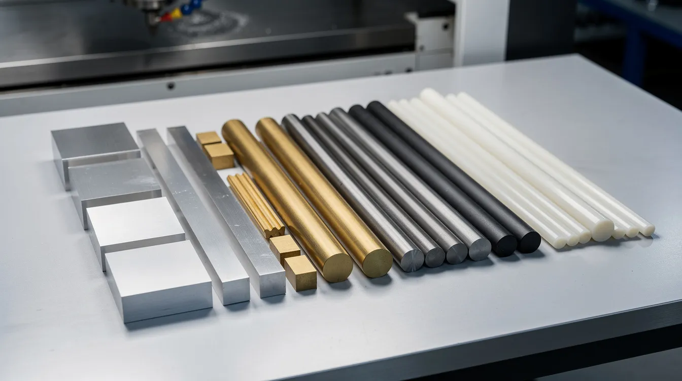
Anebon machines both metals and engineering plastics. CNC machining allows for a wide selection of materials including metals and plastics, and the choice shapes every downstream decision: tool material, feeds, speeds, coolant, and achievable surface finish.
Common metals:
|
Material |
Key property |
Typical use |
|---|---|---|
|
Aluminum 6061-T6 / 7075-T6 |
Lightweight, fast to machine |
Aerospace brackets, electronics housings |
|
Stainless steel 304 / 316 / 17-4PH |
Corrosion resistant, strong |
Medical devices, food processing |
|
Carbon steel (1018, 4140) |
High strength, lower cost |
Fixtures, tooling, automotive |
|
Brass / bronze |
Conductive, low friction |
Connectors, bushings |
|
Titanium Ti-6Al-4V |
High strength-to-weight |
Aerospace, medical implants |
|
Copper |
Thermal/electrical conductivity |
Heat sinks, electrical contacts |
Common plastics: ABS, POM (Delrin), PEEK, polycarbonate, nylon (PA), PTFE, and acrylic. These serve prototypes, insulating components, and low-load mechanical parts.
Material impact on machining. Aluminum cycle times run 30 to 80% shorter than the same geometry in stainless steel, because aluminum allows higher spindle speeds and feed rates. Titanium requires slow surface speeds, high torque, and aggressive coolant strategies. Plastics need sharp tools and careful chip evacuation to avoid melting. Surface finish for metals ranges from Ra 3.2 µm (standard) down to Ra 0.2 µm with finishing or grinding passes.
Design for CNC: Reducing CNC Machining Cost and Lead Time
80% of manufacturing costs are determined in the design stage. Modern designers use DFM guidelines to reduce costs before a single chip is cut. Here is a practical DFM checklist for design engineers sending files for CNC precision machining.
-
Tolerance only where needed. Specifying ±0.01 mm on a non-functional surface that could tolerate ±0.05 mm adds slower finishing passes, more inspection, and higher cost. Tight tolerances increase machining time and costs. Reserve tight callouts for mating surfaces, bearing bores, and seal grooves.
-
Use standard hole and thread sizes. Standard drill sizes from 1 mm to 20 mm are stocked in most shops. Non-standard sizes require custom CNC tools or special-order drills, adding cost and lead time.
-
Maintain wall thickness. Walls thinner than 1.5 times the tool diameter deflect under cutting forces, causing chatter and dimensional variation. Keep minimum wall thickness above 0.8 mm for metals, 1.5 mm for plastics.
-
Generous internal corner radii. Internal corners smaller than the milling cutter radius force the programmer to use a smaller tool, which cuts slower. Matching internal radii to standard end mill diameters (e.g., R1.5, R2, R3 mm) reduces tool changes and cycle time.
-
Minimize deep pockets. Pocket depth beyond 4 times the tool diameter requires extended-reach cutters that are less rigid and cut slower. Shallow pockets machine faster and hold tighter tolerances.
-
DFM feedback at quoting. Anebon reviews every incoming design for manufacturability before quoting. Orienting a part so multiple features machine in one clamping, instead of two or three re-clampings, reduces alignment errors and labor hours.
CNC Machining Cost: What Drives Pricing?
CNC machining costs vary based on material and machine type. Anebon provides transparent line-item quotations so buyers see where their money goes. Here are the primary cost drivers.
-
Part complexity. A flat aluminum bracket with pockets and through-holes runs on a 3-axis VMC in minutes. A 5-axis titanium medical implant with compound curves requires specialized CNC machinery, longer cycle times, and more expensive tooling. Simple parts may cost $50 to $150 each for prototypes. Complex, low-volume runs may cost hundreds or thousands per part.
-
Material. Titanium and nickel superalloys cost more per kilogram and wear tools faster than aluminum or mild steel. Material procurement for exotic grades may add days to the lead time.
-
Tolerances and surface finish. Moving from ±0.05 mm to ±0.01 mm adds finishing passes and inspection time. Requesting Ra below 0.8 µm may require grinding or polishing as a secondary operation.
-
Quantity. Setup, CNC programming, and fixture costs are fixed regardless of batch size. Higher production volumes usually reduce per-part costs because those fixed costs amortize across more units. CNC machining is more cost-effective for high-volume production runs than low-volume prototyping on a per-unit basis.
-
Setup and programming. First-run programming, fixture design, and prove-out represent one-time costs. Repeat orders skip most of this.
-
Secondary processes. Heat treatment, anodizing, plating, and painting each add 2 to 5 days and additional cost per part.
-
Inspection and documentation. PPAP packages, material certificates, RoHS/REACH compliance reports, and FAI documentation add labor. Quality control ensures parts meet ISO 9001:2015 standards, which requires documented evidence.
-
Limitations. High initial costs for CNC equipment and the need for skilled operators are real constraints. A 5-axis machine may cost several hundred thousand dollars; amortizing that requires steady utilization.
CNC machining requires fewer skilled labor hours compared to manual machining on repetitive runs, but the upfront investment in complex machinery and CNC programming is higher.
The People Behind the Machines: CNC Machinists and Operators
CNC machinists and CNC machine operators are distinct roles, though they overlap in smaller shops.
-
CNC machinists program toolpaths, select feeds and speeds, design fixtures, troubleshoot process issues, and optimize cycle times. They read technical drawings with GD&T, choose appropriate factory tools and machine tools, and verify first articles using calipers, micrometers, and CMMs. Five-axis and tight-tolerance work (aerospace, medical) demands years of hands-on experience.
-
A CNC operator loads raw stock, initiates programs, monitors the machine during cutting, performs basic quality checks with go/no-go gauges, and unloads finished parts. Operators also perform routine tasks that keep machines accurate: regular maintenance and calibration are vital for quality control.
-
Anebon’s team structure. Anebon’s facility in Dongguan combines process engineers, machinists, and dedicated inspectors. Engineers handle DFM and CNC programming; machinists run prove-outs and optimize; inspectors verify every lot against the drawing. This separation ensures that precision CNC machining standards meet international OEM expectations. Metalworking skills remain essential even as modern CNC machines handle more of the execution.
Surface Finishes and Secondary Operations
Many CNC parts require surface treatments after machining to meet functional or cosmetic requirements.
-
Mechanical finishes. Deburring removes sharp edges. Tumbling smooths small parts in bulk. Bead blasting produces a uniform matte texture. Brushing creates directional grain lines. Polishing brings surfaces to a mirror finish.
-
Surface treatments. Anodizing (Type II for color and corrosion resistance; Type III hard anodizing for wear resistance) is the most common treatment for aluminum CNC components. Powder coating adds thick, durable color layers. Passivation removes free iron from stainless steel surfaces. Electroplating (nickel, chrome, zinc) adds hardness or conductivity. Black oxide provides mild corrosion resistance on steel.
-
Heat treatments. Hardening, tempering, and aging change the mechanical properties of steels and aluminum alloys. These processes typically happen before final finishing to avoid distortion after tight-tolerance machining.
-
Integrated service. Anebon manages these post-machining operations so OEM clients receive ready-to-assemble metal parts. Consolidating machining and finishing under one supplier eliminates the coordination overhead of shipping parts between vendors.
CNC Machining Applications by Industry
CNC manufacturing is critical across multiple manufacturing methods and sectors. CNC machining is widely used in industries like aerospace and automotive; here is how each sector relies on it.
-
Aerospace. CNC machining is vital in aerospace for complex geometries. Structural brackets from aluminum 7075-T6, turbine blade roots from Ti-6Al-4V, and thin-wall panels all require 5-axis contouring, tolerances of ±0.005 to ±0.01 mm, and full material traceability. Anebon provides aerospace CNC machining services certified to international standards.
-
Medical devices. The medical industry uses CNC machining for custom implants and instruments. Orthopedic implants machined from titanium or stainless steel need biocompatible surface finishes and tolerances within ±0.005 mm. Surgical equipment housings and diagnostic device components (including parts for MRI machines) also depend on precision CNC machining.
-
Automotive and transportation. CNC machining produces durable components for the transportation sector: engine blocks, drivetrain housings, motor mounts, and precision jigs. The automotive industry runs high volumes, so cost sensitivity is high, but fuel injectors and sensor housings still require ±0.02 mm or tighter control.
-
Electronics and robotics. CNC machines create precise parts for the electronics industry: heat sinks with fine fins, RF enclosures, connector housings, and computer components. Flatness and thermal conductivity matter as much as dimensional accuracy.
-
Oil and gas. The oil and gas industry relies on CNC for well-machined components such as valve bodies, flanges, and downhole tool housings that must withstand high pressures and corrosive environments.
-
Industrial machinery. Custom gears, spindle housings, linear guides, and fixture plates for factory tools and automation equipment are standard CNC work. These parts often involve mass production runs once designs are validated.
CNC machining enables rapid prototyping and easy adjustments to designs, making it the preferred manufacturing process across these sectors.
Why Choose Anebon Metal Products Limited for CNC Machining?
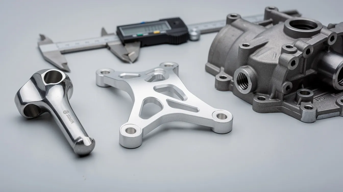
Anebon Metal Products Limited is a Dongguan, China-based precision manufacturer founded in 2010. The company serves overseas OEMs with CNC machining, die casting, and sheet metal fabrication under one roof.
-
Precision capability. Standard tolerance of ±0.01 mm; critical features held to ±0.002 mm after DFM review. Many competing shops standard at ±0.02 to ±0.05 mm. Anebon’s precision CNC machining capability places them at the tighter end of the manufacturing industry.
-
Certifications. ISO 9001:2015 (quality management) and ISO 14001:2015 (environmental management). ISO 9001:2015 and ISO 14001:2015 certifications are directly relevant in precision manufacturing, especially for aerospace and medical OEMs evaluating supply chain compliance.
-
Machine range. 3-axis and 5-axis milling machines, CNC lathes with live tooling, and grinding; covering everything from simple turned parts to complex 5-axis mold components.
-
Material and finish breadth. Aluminum, stainless steel, titanium, copper alloys, engineering plastics, plus in-house and managed surface finishing services including anodizing, plating, powder coating, and heat treatment.
-
International support. English-speaking engineering team, DFM-based quoting, and pre-programmed software for digital inspection reports that follow today’s CNC protocols for traceability and documentation.
How to Start Your CNC Machining Project with Anebon
Starting a CNC machining project is straightforward when you prepare the right information up front.
-
Prepare your files. Export your CAD model as a STEP or IGES file. Include a 2D drawing with dimensions, tolerances, surface finish callouts, and material specification. The more complete the drawing package, the faster and more accurate the quote.
-
Define your requirements. Specify quantity (prototype vs. production), material, finish, and any compliance needs (RoHS, REACH, material certificates). CNC machining can be used for both prototypes and high-volume production, so clarify your stage.
-
Submit an RFQ. Send files to Anebon via their online portal or email. Anebon’s engineering team reviews the design, provides DFM feedback, and returns a quote with pricing, lead time, and any suggested geometry changes.
-
Lead times. Typical turnaround for rapid prototyping of simple CNC parts is 3 to 7 working days from drawing approval. Surface treatments add 2 to 5 days. Production runs after sample approval depend on quantity and complexity.
-
Consolidate your RFQ. If your project includes machined parts, die castings, and sheet metal, submit them together. Anebon’s small batch CNC machining services and broader manufacturing capabilities let you source from one vendor, cutting coordination time and shipping costs.
Whether you need a single prototype or a production run of 10,000 units, the right preparation turns a CAD file into a finished part in days. Contact Anebon’s engineering team to discuss your CNC machining process needs, get DFM feedback, and request a quote.