Mastering Bent Sheet Metal: Techniques for Precision and Performance
Bent Sheet Metal: Design, Bending Methods, and Precision Fabrication
Introduction: What “Bent Sheet Metal” Means in Modern Fabrication
Sheet metal bending is a foundational metal fabrication process that transforms flat blanks into three-dimensional shapes-flanges, channels, enclosures, and complex brackets-through controlled plastic deformation. In modern OEM manufacturing, bent sheet metal parts are central to product design because they deliver structural integrity, minimal material waste, and clean aesthetics with fewer welds or joints. Between 2024 and 2026, rising demand for lighter assemblies and tighter tolerances has made precise bending more technically challenging and more critical than ever. Sheet metal bending can create parts from a single piece of material, eliminating assembly steps and reducing cost.
Before diving into methods and design rules, it helps to define several terms that will appear throughout this guide. The bend radius (specifically the inside bend radius) is the curvature on the inner surface of a bend. Bend allowance quantifies material used in a bend-the arc length along the neutral axis that must be added to flat dimensions. Bend deduction is subtracted from flange lengths for flat patterns, giving you the correct blank size. And bend relief refers to small notches cut near bend intersections to prevent tearing or distortion.
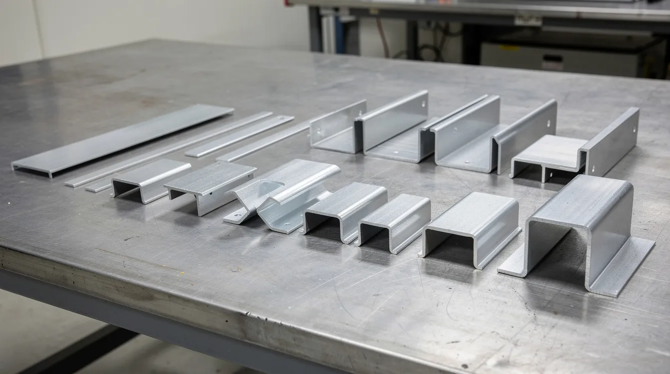
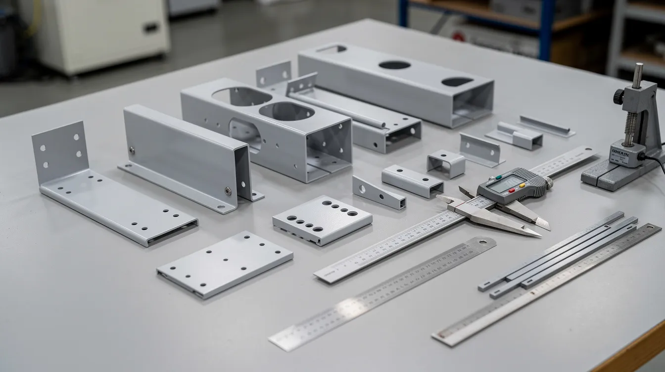
Common bent sheet metal products include channels, angles, and custom-formed parts used across many industries. Typical applications span electronics housings, battery trays, medical instrument brackets, automotive body panels, and robotics frames. Bent sheet metal products are vital for structural framing and exterior finishing, and bending is essential in constructing structural support and roofing materials. Material selection is critical in manufacturing bent sheet metal products, and the typical sheet thickness for precision work ranges from about 0.5 mm for thin electronic chassis up to roughly 6 mm for heavier structural brackets. Bending is commonly used in automotive and industrial equipment manufacturing, making it one of the most versatile processes in fabrication.
Anebon Metal Products Limited is a China-based ISO 9001:2015 and ISO 14001:2015 certified manufacturer offering precision sheet metal and CNC fabrication services, serving overseas OEMs from rapid prototyping through full-scale production.
How Sheet Metal Bending Works in Practice
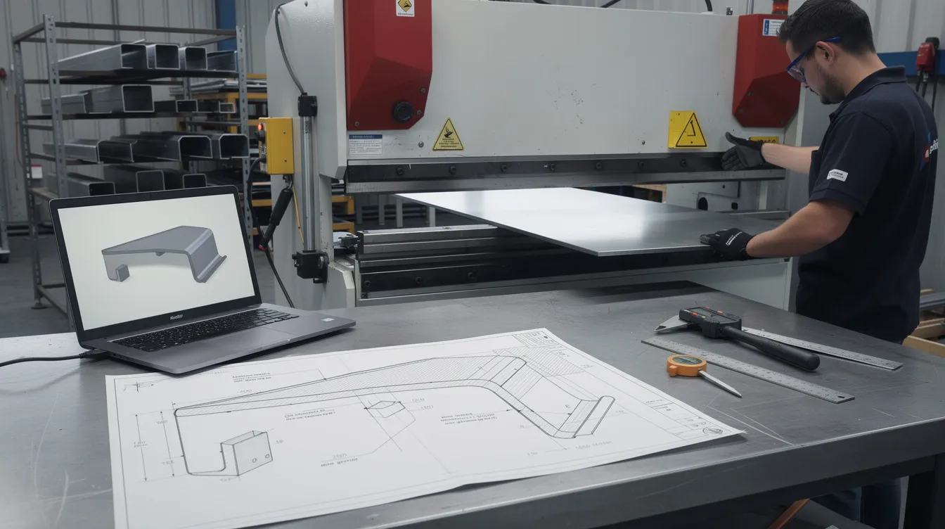
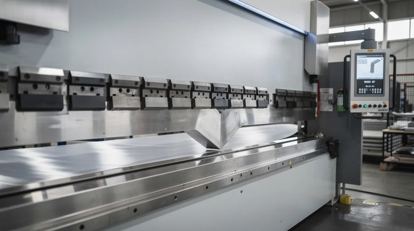
The bending process starts with a flat sheet of metal, cut to shape by laser cutting or punching. Force is applied to a flat sheet of metal to deform it plastically at an angle: the blank is placed over a bottom die-typically V-shaped-on a press brake, and a punch descends from above, pressing the material into the die cavity. As the punch pushes deeper, the metal undergoes permanent plastic deformation in the bend zone, achieving the desired angle once the tooling is withdrawn. A press brake is commonly used in sheet metal bending processes, and V-bending is the most common method for bending sheet metal across the industry.
CNC brake presses used in precision shops like Anebon typically range from 80 to 200 tons of bending force for mid-thickness work (0.5–6 mm), with bend lengths up to approximately 3 meters. These machines feature programmable back-gauges, hydraulic crowning systems to compensate for bed deflection over long bends, and multi-axis control for consistent results. Brake presses can accommodate material thicknesses from 0.5mm to 20mm, and bending can accommodate materials up to 20mm thick, though most OEM precision work stays within the 0.5–6 mm range. CNC bending can achieve accuracy levels of ±0.05 mm on ram positioning, which translates to reliable, repeatable parts. For more on which tool is used to bend sheet metal, Anebon has published a dedicated guide.
There are two primary approaches to understand here. In air bending, the punch does not fully engage the bottom of the V-die-air bending leaves a gap between the die and material. The final bend angle is controlled entirely by punch penetration depth, making this method flexible (one die can produce many angles) but more sensitive to springback. In bottom bending, the material is forced fully into the die profile, which more closely defines the angle and reduces springback because of greater contact area, but it demands matched tooling geometry and higher tonnage.
Designers normally specify the inside bend radius because it governs internal stress, thinning risk, and flat pattern geometry. The outside radius simply equals the inside radius plus the material thickness. Between the inner surface (in compression) and the outer surface (in tension) lies the neutral axis-a theoretical line where material stretches zero. Modern CNC controls adjust ram position and crowning to hold ±1° on bend angle and about ±0.2 mm on flange length for standard carbon steel and stainless steel parts.
Key components to visualize in the bend zone:
-
Punch: The upper tool (top tool) that moves downward to deform the sheet.
-
Die: The bottom tool (usually V-shaped) that supports the sheet from below.
-
Flanges: The flat portions of the sheet on either side of the bend line.
-
Neutral axis: The imaginary line within the material thickness where there is no strain-neither tension nor compression.
Key Geometry Concepts: Neutral Axis, K‑Factor, Bend Allowance & Bend Deduction
The neutral axis is the “no-tension, no-compression” line inside the bent material. When you bend metal, the outer surface stretches while the inner surface compresses, and the neutral axis shifts toward the inside surface. How far it shifts depends on the bend radius, the material type, and the bending method used. Understanding this shift is essential for calculating accurate flat pattern dimensions.
The K-factor predicts material stretch during bending by expressing the ratio of the neutral axis location (measured from the inside bend surface) to the total material thickness. The K-factor determines where the neutral axis shifts during bending: a K-factor of 0.50 means the neutral axis sits exactly at mid-thickness, while a lower value means it has shifted closer to the inside. K-factor varies between 0.3 and 0.5 for bending-the K-factor typically ranges between 0.3 and 0.5 across common materials. For air bending mild steel with a die opening around 6–8 times the sheet thickness, K is roughly 0.44. Stainless steel tends slightly higher, while softer aluminum alloys tend slightly lower. The exact value changes with material temper, inside radius, and tooling geometry, which is why experienced fabricators validate K-factors empirically rather than relying solely on textbook numbers.
Bend allowance is the arc length along the neutral axis consumed by the bend-it represents how much length must be added to the sum of flat flange dimensions to calculate the correct flat pattern length. The bend allowance formula is expressed as: BA = (π ÷ 180) × bend angle × (inside bend radius + K-factor × material thickness). Bend deduction offers an alternative approach: you take the sum of the outside flange lengths and subtract the bend deduction to get the flat pattern. The relationship involves the outside setback, calculated as (inside radius + thickness) × tan(half the bend angle), with BD = 2 × outside setback − bend allowance.
Here is a concrete example. Consider 1.5 mm thick 304 stainless steel, air bent to 90°, with an inside bend radius of 1.5 mm and a K-factor of approximately 0.40. The bend allowance calculates as: BA = 1.5708 × (1.5 + 0.40 × 1.5) = 1.5708 × 2.1 ≈ 3.30 mm. The outside setback is (1.5 + 1.5) × tan(45°) = 3.0 mm, so BD = 2 × 3.0 − 3.30 = 2.70 mm. If one flange measures 40 mm and the other 30 mm (outside dimensions), the flat pattern length would be 70 − 2.70 = 67.30 mm. This kind of calculation is standard in sheet metal design software, but the accuracy depends entirely on having the right K-factor for your specific material and process.
Anebon’s engineers validate K-factors and bend deductions through small trial bends-test coupons for each combination of material, temper, thickness, and die opening. These process-specific values are then stored in the CAD/CAM system so that flat pattern geometry remains correct and consistent across production runs, whether the job calls for ten prototypes or ten thousand parts.
Material Behavior: Grain Direction, Cold Bending, and Springback
The same bend radius and bend angle will behave differently depending on the material properties of the blank-specifically grain direction, material yield strength, temper, and whether you use cold bending or apply localized heat. Materials should have consistent thickness for effective bending; thickness variation across the blank introduces unpredictable springback and dimensional errors.
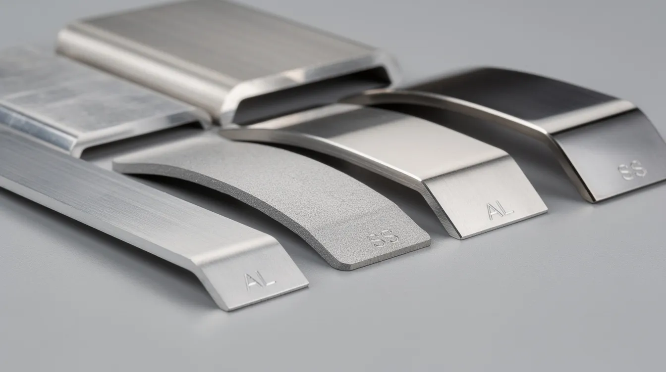
Grain direction from the rolling mill creates directional material properties. Grain direction affects the brittleness of the metal when bent, and bending against the grain increases the risk of cracking. For alloys like 5052-H32 or 6061-T6 aluminum, tighter inside bend radii are safer when bending transverse (perpendicular) to the grain, where the material shows better ductility. Along the grain, microcracks are more likely, especially in harder tempers. For a deeper discussion of how to bend stainless steel sheet metal, including grain considerations specific to 304 and 316, see Anebon’s detailed guide. When choosing materials, keep in mind: steel is preferred for strength while aluminum is used for lightweight applications. Aluminum is lightweight and corrosion-resistant for aerospace applications. Stainless steel is used for medical and food-processing equipment due to its corrosion resistance and cleanability. Mild steel is durable and cost-effective for general frames. And copper is ideal for electrical panels due to its conductivity. This range of material options means that material type drives nearly every bending parameter.
Cold bending-bending at room temperature on brake presses-is Anebon’s default approach for sheet gauges from roughly 0.6 to 6 mm. Most OEM sheet steel, aluminum, and stainless steel work falls into this range. Hot forming or stress relief may be considered for thicker materials above 6–8 mm, or for high strength materials like 6061-T6 or spring-temper 301 stainless that risk cracking when bent cold at tight radii. Strain hardening during cold bending can increase hardness in the bend zone, which is sometimes beneficial for structural integrity but can complicate subsequent forming operations.
Springback is the elastic recovery that causes the bend angle to “open” slightly after the load is removed, pushing the part back toward its original shape. Springback typically amounts to 1-2° after bending for most common alloys. Higher material yield strength, harder tempers, and larger bend radii all increase springback. For example, forming a 90° design angle in 2 mm 304 stainless steel might require the press brake to over bend to approximately 87.5–88° to compensate for roughly 2–3° of springback in air bending. In contrast, mild steel of the same gauge might only spring back 0.75–1°. Springback generally amounts to 1-2° of difference, which sounds small but accumulates quickly across multiple bends on a single part. Research into electrically assisted air bending for 304 stainless shows promise for reducing springback without full hot forming.
A useful rule of thumb for minimum inside bend radius by material group: for mild steel (annealed), the inside bend radius should be greater than the thickness of the sheet metal-typically at least 1×T. For 304 stainless (annealed), use 1–1.5×T. For 6061-T6 aluminum, expect to need 1.5–3×T depending on gauge and grain direction. As a concrete example, bending 2 mm thick 304 stainless with an inside radius of 2 mm (1×T) is generally safe; bending 3 mm 6061-T6 may require a radius of 4.5–9 mm to avoid cracking, depending on orientation.
Common Bending Methods and When to Use Them
Different bending methods exist to control bend angle, radius, surface finish, and dimensional accuracy. The choice of bending method depends on part geometry, material type, production volume, and tolerance requirements. Here is a practical overview of the most common approaches from a DFM and OEM engineering perspective.
Air bending is the most common bending method in CNC brake presses and offers the greatest flexibility. A single V-die and punch set can produce a wide range of angles simply by varying ram depth. The required bending force is typically one-third to one-half of what bottoming or coining demands for the same material thickness and die opening. However, air bending relies heavily on accurate K-factor values and springback compensation-if your material properties vary between batches, angles can drift. Air bending is best suited when tolerances of ±1° are acceptable and production requires frequent angle changes without swapping tooling.
Bottom bending and coining deliver higher precision. In bottom bending, the metal is forced to fully conform to the die angle, producing tighter tolerances and less springback than air bending. Coining goes further-applying enough bending force to plastically deform the material throughout the bend zone, effectively eliminating springback. The trade-off is significantly higher tonnage, more tooling wear, and the need for specialized tooling matched to each specific inside bend radius and desired angle. Bending is used in the automotive industry for body panels and chassis components where these methods ensure the sharp angles and repeatable accuracy that assembly demands.
Roll bending uses three-roll machines to produce larger bend radii, gentle curves, and full cylinders. Rolling can bend materials from 1mm to over 50mm in thickness, making it suitable for guards, ducts, tanks, and architectural elements. For a practical guide on how to bend sheet metal into a circle, including roll-bending setup, see Anebon’s tutorial. Precision of angle is lower than press brake work, and flatness or twist can be concerns on longer pieces.
Three-point bending, folding/wiping, and rotary bending serve special cases. Three-point bending offers very precise angle control and is often used for longer sheet metal components where surface sensitivity matters. Folding and wiping are preferred for clean edges on painted appliance panels or elevator doors, where the automated process minimizes surface contact marks. Rotary bending uses a rotating die to form the bend without the punch contacting the outer surface, which is ideal when cosmetic finish on the outer surface is critical.
Design Rules for Bent Sheet Metal Parts
Small design adjustments in bend radius, flange length, hole placement, and bend relief can make bent parts cheaper, faster to produce, and more robust in assembly. Design guidelines help prevent defects during sheet metal bending, and applying them early in CAD saves significant time and cost downstream.
For minimum bend radius, use a standard inside bend radius equal to 1× material thickness wherever possible for mild steel or annealed stainless steel. For harder tempers like 6061-T6 aluminum or 301 stainless, increase to 1.5–3×T or more. Using the same radius across all bends on a part simplifies tooling and speeds production. Tight bends at radii below 1×T risk cracking on the outer surface, increase required tonnage, and amplify springback-there is always a trade-off between a compact design and manufacturability. Larger bend radii reduce stress concentrations and improve fatigue life but may not fit packaging constraints. Refer to the sheet metal thickness selection guide for more on balancing radius and structural needs.
Minimum flange length depends on V-die opening and tooling geometry. Very short legs may require specialized tooling or secondary operations. As a concrete example: with 1.0 mm sheet steel on a 12 mm V-die opening, you need approximately 8–10 mm minimum flange length for stable bending. Flanges shorter than about 4× material thickness are challenging and risk collapse or distortion. When designing a flange in sheet metal, always verify your flange length against the tooling your fabricator plans to use.
For bend orientation versus grain direction, align critical flanges so that bending occurs transverse to the grain whenever the part is fatigue-sensitive-hinges, brackets under vibration, or any component subjected to cyclic loading. If all bends run parallel to the grain, brittle failure becomes more likely in alloys like 6061-T6.
To add bend reliefs at intersections of perpendicular bends, use rectangular or round notches that let the material flow freely without tearing or producing cosmetic defects. A practical rule: relief width should be at least equal to the material thickness, and relief length at least 1.5× thickness. These small features separate flanges at the intersection and prevent distortion where two bend lines converge.
Features Around Bends: Holes, Notches, Slots, and Countersinks
Poorly placed features near bend lines are one of the most common causes of scrap in bent sheet metal parts. A hole or slot that sits too close to a bend will distort, elongate, or crack during forming-turning an otherwise good part into waste.
The simplest rule: holes should be a minimum of 2.5 times the sheet thickness from the bend line. For a 1.5 mm blank, that means hole edges should start no closer than about 3.75 mm from the bend center line. For larger holes, soft alloys, or thicker materials, increase this distance further. An extruded hole or tapped feature near a bend requires even more clearance because the forming process for the extrusion itself creates local thinning that interacts poorly with the bend zone.
Notches and bend reliefs control material flow when two flanges meet at 90° or in Z-bends and joggles. Without a relief, the material at the intersection is forced to stretch and compress simultaneously, leading to tearing, bulging, or warped flanges. Rectangular or semi-circular reliefs sized at a width equal to material thickness and a length of 1.5× thickness handle most situations cleanly.
Countersinks deserve special attention. Countersunk holes near edges or bends are especially prone to distortion because the countersink removes material asymmetrically, reducing the effective sheet thickness locally. In thin sheet (for example, 1 mm 304 stainless), keep countersinks well away from both the bend line (at least 2–3× thickness) and free edges to avoid cracking or cosmetic failure.
Consider a concrete example: a control panel made from 1.5 mm galvanized steel with 90° flanges and M4 countersinks. In your sheet metal design, position the center of each countersink at least 3.75 mm from the nearest bend center line, ensure the flange length exceeds 6 mm (4×T), and never place a countersink directly on the bend itself. These straightforward rules keep the part bent accurately and eliminate the most common forming defects.
Managing Tolerances, Springback, and Bend Sequence
Typical dimensional tolerances for production bent parts that Anebon can hold: bend angles have a standard tolerance of ±1° for standard parts, and bend length tolerances are typically ±0.20 mm per bend on linear dimensions. For higher-precision work-shorter bends, consistent material lots, bottoming or coining-tighter tolerances of ±0.25–0.5° on angle and ±0.15 mm on linear dimensions are achievable. Longer bends and exotic alloys generally widen these ranges.
Springback compensation is a core part of production planning. The primary strategy is overbending: if a part is over bent slightly past the target, elastic recovery brings it back to the desired angle. For instance, forming 2 mm 304 stainless steel for a 90° design angle typically means setting the machine to form at approximately 87.5°, so that the ~2.5° springback restores the correct angle. Selecting die angles, controlling inside bend radius, and choosing between air bending and bottom bending all influence how much compensation is needed. A larger radius produces more springback, while bottoming reduces it by forcing greater contact with the tooling geometry.
Bend sequence planning is critical for parts with multiple bends-typically four to ten bends in enclosures, chassis, or complex brackets. The order in which bends are formed affects whether the part will collide with the press brake frame, whether cosmetic surfaces get scratched, and how cumulative tolerance buildup propagates through the part. For more on optimizing sheet metal forming sequence in complex geometries, Anebon has published a detailed approach.
Anebon uses 3D CAD and CAM tools to simulate bend sequences, flat patterns, and potential interferences before cutting a single blank. This approach reduces trial-and-error for overseas OEM customers, who can review simulated results and DFM feedback before committing to tooling or production. When preparing drawings for quotation, include explicit tolerance callouts on critical dimensions (post-bend), note which surfaces are cosmetic, and specify any required bend sequence constraints.
From Prototype to Production: Bent Parts with Anebon Metal Products Limited
Anebon Metal Products Limited, founded in 2010 and based in Dongguan, Guangdong, China, is a precision OEM manufacturer combining sheet metal fabrication, CNC machining, and die casting to deliver complete product assemblies. The company serves aerospace, medical, electronics, and robotics industries with both rapid prototyping and full-scale production.
Anebon’s bent sheet metal capabilities include CNC press brake forming, laser cutting and punching for flat pattern preparation, hardware insertion, spot welding, and a full range of surface finishes-powder coating, anodizing, and plating-to meet functional and cosmetic requirements. Every part can be produced as a custom precision sheet metal bending part tailored to the customer’s specifications. The company also operates CNC machine centers for post-bend machining when tight tolerances on specific features demand it.
On tolerances, Anebon achieves ±0.15–0.20 mm on linear dimensions and ±1° on bend angles as standard. For machined features on bent parts-such as reamed holes or mating surfaces-accuracy down to ±0.002 mm is available. The material range covers aluminum 5052 and 6061, stainless 304 and 316, cold-rolled and hot-rolled carbon steel, galvanized sheet steel, and titanium where lightweight or biocompatibility requirements call for it. This breadth supports work from single-piece prototypes to production runs of thousands.
Before production begins, Anebon provides DFM feedback on bend radius, bend allowance, bend relief, grain direction, and hole placement. This review helps overseas OEMs avoid issues like cracking on tight bends, warping from incorrect bend sequence, or dimensional mismatch in final assemblies. The goal is to ensure every part is bent accurately the first time, eliminating costly rework and delays.
If you have an upcoming project-whether it is an enclosure, bracket, chassis, or structural component-send your 3D models and 2D drawings to Anebon’s engineering team for review and bend optimization feedback.
How to Prepare Files and Request a Quote for Bent Sheet Metal Parts
When requesting a quote for bent sheet metal parts, include the following: a 3D CAD model (STEP or IGES preferred), 2D drawings with clear bend notes (bend lines, inside bend radius, bend angle, material specification and temper), surface finish requirements, and expected quantities distinguishing prototype from production volumes. Clearly call out which dimensions are critical post-bend-especially flange-to-hole distances, hole positions relative to bends, and overall assembled fit dimensions.
Specify allowable tolerances explicitly: angle (e.g., ±1° or tighter), linear dimensions (e.g., ±0.20 mm), and note any dimensions driven by bend deduction and flat pattern length accuracy. If your existing design has validated specific bend radii or a preferred bending method (air bending versus bottom bending), include that information-it helps Anebon use validated parameters and reduces risk on first articles.
Anebon can handle flat pattern development and bend allowance calculations internally using stored, process-validated data for each material and tooling combination. However, if you have a known K-factor or bend deduction from previous production, sharing it accelerates the process. For instant pricing estimates and DFM review, Anebon’s engineering team typically responds within 24–48 hours for parts of moderate complexity.
Ready to start your next project? Contact Anebon Metal Products Limited with your STEP or IGES files and 2D drawings for DFM feedback on your next bent sheet metal enclosure, bracket, or chassis. The team is structured to support overseas time zones, and quotation turnaround is typically within 24–48 hours.