Mastering Bending Steel Sheet: Techniques and Tools for Precision Work
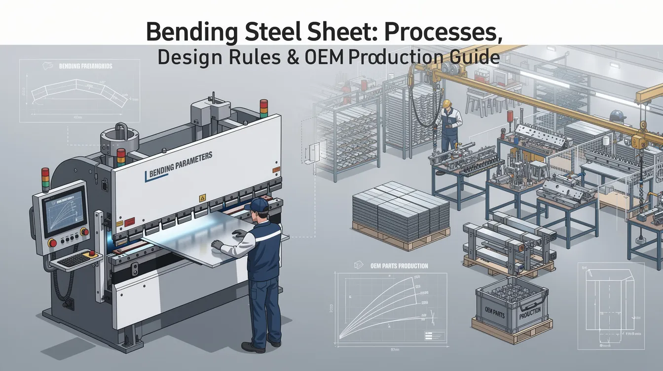
Bending Steel Sheet: Processes, Design Rules & OEM Production Guide
Introduction to Bending Steel Sheet
Bending steel sheet is the process of plastically deforming flat steel stock around a straight axis to form flanges, channels, enclosures, brackets, chassis, and machine covers. If you are a design engineer or OEM buyer asking how to bend steel sheet accurately and cost-effectively, this guide walks through every critical decision, from material selection and bend radius to springback compensation and quality control. Steel remains the most common sheet metal for OEM industrial parts because it delivers superior strength per unit cost and broad global availability, whereas aluminum is lighter and offers better natural corrosion resistance but at a higher price point and lower stiffness.
Modern bending sheet metal production relies on CNC press brakes, roll bending equipment, and other calibrated machines to achieve repeatable angles, tight tolerances, and clean bent parts. These automated systems, paired with laser cutting lines, enable production-ready sheet metal parts with minimal manual intervention. Anebon Metal Products Limited, an ISO 9001:2015 and ISO 14001:2015 precision sheet metal fabricator based in Dongguan, China, has served overseas OEMs since 2010, specializing in designing, prototyping, and producing precision bent steel components from small batches through full production runs.
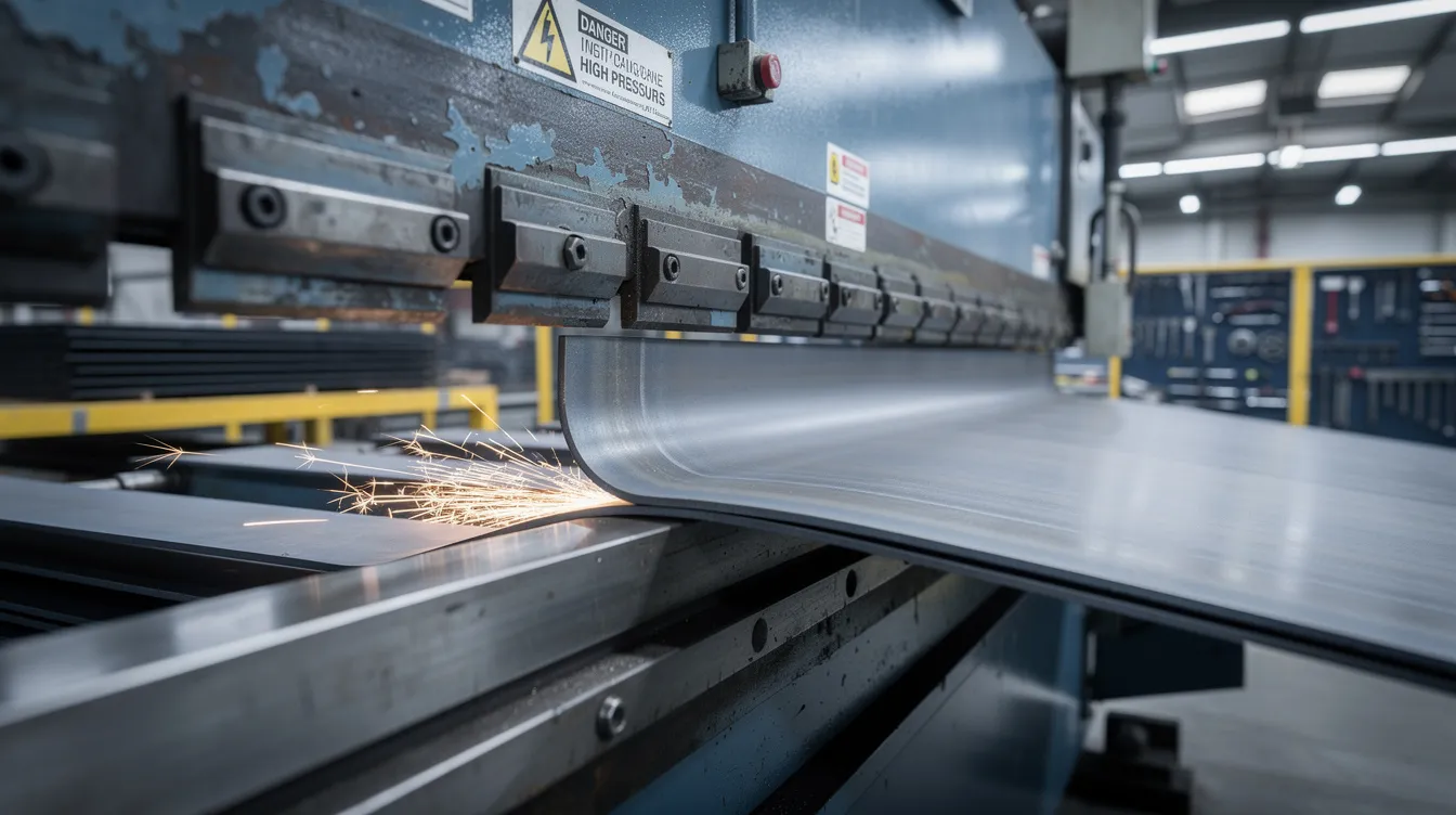
What Is Sheet Metal Bending? (With Focus on Steel)
Sheet metal bending is the permanent (plastic) deformation of sheet stock, typically 0.5 mm to 8.0 mm thick for steel, around a straight axis to create flanges, hems, and formed profiles. During the bending process, a neutral axis forms within the material thickness. Metal on the outer surface stretches under tension while material on the inner surface compresses. Once the force is removed, elastic recovery, known as springback, causes the part to partially return toward flat, altering the final angle slightly. Cold bending is the standard for high precision work, and virtually all OEM steel bending is performed at room temperature.
The terms “bending sheet metal,” “sheet metal forming,” “press braking,” and “die bending” are used interchangeably across manufacturing documentation. Regardless of terminology, sheet metal bending uses press brakes and rollers for shaping flat steel into three-dimensional components. For steel sheet, bending is used to produce brackets, enclosures, panels, rails, and structural stiffeners far more efficiently than machining from solid plate or welding multiple pieces. Bending is faster and cheaper than welding or riveting for most geometries, and it preserves material integrity across the bend zone.
In professional OEM production, typical tolerances include ±0.2 mm for linear dimensions and ±1° for angles. With advanced process control, CNC bending machines can achieve accuracy levels of ±0.05 mm on critical feature-to-bend distances. As a practical example, consider an enclosure made from 2.0 mm mild steel: flanges of 20 mm, holes positioned 5 mm from flanged edges, angle tolerance of ±1°, bent on a CNC press brake using a V-die width of approximately 16 mm (roughly 8× the material thickness), and requiring about 20–30 tons of force across a 500–800 mm length.
Core Bending Processes for Steel Sheet
Bending steel sheet can be accomplished through several processes. The CNC press brake is the primary industrial method, supported by roll bending for curved forms and folding machines for long straight bends on large panels.
Press brake air bending is the most flexible approach. The punch presses the sheet partway into the V-die, and the final angle is controlled by ram depth rather than die geometry. This method uses the lowest tonnage and accommodates a wide range of thicknesses. V-bending is a commonly used method to achieve exact angles in production, and air bending is its most versatile variant. Because air bending leaves a gap between the material and die, the sheet only contacts the punch tip and the two die shoulders, which means one die can produce multiple angles simply by adjusting depth.
Bottom bending (also called bottoming) forces the sheet fully to the die bottom, and bottom bending creates more accurate angles with less springback than air bending. It requires higher tonnage and closer tooling fit but is preferred for features demanding tight angular precision. Coining takes this further, plastically stamping the bend zone to virtually eliminate springback, though at even higher force and slower cycle times.
Roll bending uses sets of three or four rolls to gradually form curved shapes such as cylinders and cones. Panel benders and folding machines clamp the sheet along the bend line and swing a beam to fold the free portion, making them efficient for long, straight bends on thin to medium steel panels. Manual sheet metal brake tools serve prototyping and very low-volume work but lack the repeatability needed for production.
Anebon typically uses CNC press brakes integrated with fiber laser cutting lines. Laser cutting first ensures precise hole and feature positions on the flat blank, and then CNC bending forms the final shape with programmed sequences, producing consistent sheet metal parts from prototype through volume production.
Press Brake Bending of Steel Sheet
A press brake setup consists of a punch (male tool), a matching V-die (female tool), CNC-controlled backgauges that position the sheet so the bend line falls at the correct location, a controller that manages ram travel and depth, and a crowning system that compensates for beam deflection across wide bending lengths. Proper technique ensures the sheet is locked in position before applying pressure, which is critical for both accuracy and operator safety.
In air bending, the material is only partially seated in the V-die. Air bending leaves a gap between the part and the die, so the bend angle is determined by punch penetration depth rather than die geometry. This makes air bending highly flexible for steel parts ranging from thin sheet metal panels in 1 mm stainless to 4 mm mild steel brackets. Bottom bending forces the sheet fully into the die, producing tighter angular control on parts where mating surfaces must align precisely. Coining is reserved for critical-tolerance features. The V-die width must relate to material thickness for quality bending; a common rule of thumb is to select a V-die opening of 6–8 times the material thickness.
Industrial press brake machines offer high-volume repeatability and precision. Press brakes can exert forces over 100 tons, and brake presses accommodate material thicknesses from 0.5mm to 20mm. As a concrete capacity example, a 100-ton, 3 m CNC hydraulic press brake can air-bend 3 mm mild steel across its full width. For thicker sections such as 6–8 mm steel, either shorter bend lengths or machines rated at 200–300+ tons are required.
CNC backgauges position the sheet along multiple axes to ensure the bend line is placed accurately. Angle sensors or trial bends calibrate the system to compensate for springback, and some controllers include a material database that automatically adjusts ram depth for a given steel grade and thickness. Press brakes generate high forces requiring strict safety protocols, including light curtains, pinch-point guarding, proper part support to prevent tipping, and operator training. Personal protective equipment is essential when handling sheet metal, and safety glasses should be worn when handling sharp metal edges throughout the work area.
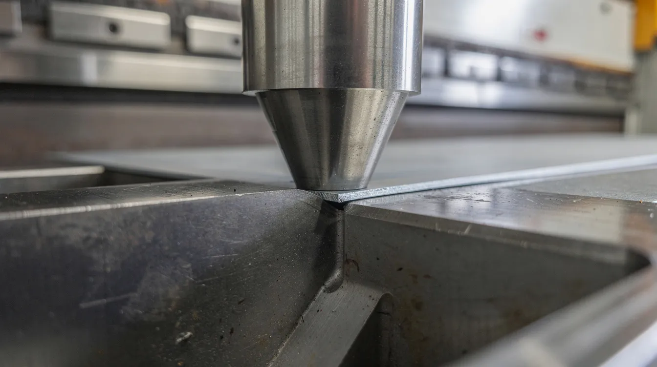
Other Methods of Bending Steel Sheet (Rollers, Folding & Hand Tools)
Roll bending uses sets of three or four rolls to gradually curve flat steel into cylinders, conical sections, guards, and housing shells. Rolling machines can bend materials from 1mm to over 50mm thick, making them suitable for everything from thin duct panels to heavy plate. For example, rolling 2.5 mm steel sheet to form a 400 mm diameter duct (approximately 200 mm radius) on a three-roll machine is a straightforward operation that produces a smooth, continuous curve.
Folding machines and panel benders clamp the sheet along the bend line and then swing a folding beam to create the bend. These are efficient for long, straight bends on large thin steel panels, such as 1–3 mm steel panels of 1–2 m in length with flanges of 20–50 mm. The sheet stays flat on the table while only the free end moves, reducing handling and the risk of marking cosmetic surfaces.
For prototyping or very low-volume work, a manual sheet metal brake, bar folder, or simple fixture made from angle iron, clamps, and a rubber mallet can bend sheet metal without a brake. These tools are typically limited to thin sheet metal of about 1.0–1.5 mm steel over 600–1000 mm of width. Using a hand brake for 0.8 mm stainless steel sample pieces, for instance, is acceptable for verifying a form before committing to CNC tooling. Scoring is useful for manual sharp-angle bends, and using a circular saw for scoring allows for a crisp precise bend on thinner gauges. However, OEM production moves to calibrated sheet metal benders and press brakes because manual methods cannot deliver the repeatability and tight tolerances required for consistent bent parts across hundreds or thousands of units.
Materials: Types of Steel Sheet for Bending
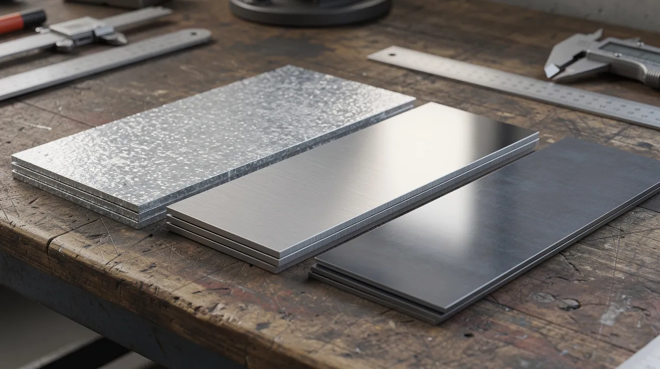
The choice of steel grade directly affects the bending process. Mild steel is the most commonly used bending material due to its moderate yield strength (roughly 200–300 MPa), good elongation, and predictable behavior. Common grades include DC01 (European designation) and SPCC (Asian designation). Hot-rolled steel is less dimensionally precise and carries more surface scale, but it is lower cost for structural applications.
Galvanized steel has a zinc coating for improved corrosion resistance, though bending must account for potential coating cracking at tight radii. Stainless steel contains at least 10.5% chromium for corrosion resistance and is widely used in food, medical, and marine applications. Common stainless grades for bending include 304, 316L (austenitic), and 430 (ferritic). Stainless exhibits higher yield strength and significantly more springback than mild steel, requiring specialized bending techniques. High-strength low-alloy (HSLA) steels offer even greater tensile strength for automotive and structural parts, but with reduced ductility and increased tooling demands.
Material thickness impacts the bending process and required tools. Thicker materials require larger bend radii for effective bending-for example, an internal radius of at least 1.5T is recommended for 304 stainless, versus approximately 0.8T for mild steel (where T equals thickness). Anebon’s standard handling range covers 0.5–8.0 mm for steel bending, with thicker gauge material possible depending on part geometry and press tonnage. Beyond steel, Anebon supports aluminum alloys (which can be bent to tight radii without cracking), copper (a soft metal that allows easy bending and forming), brass, and titanium, though this article focuses on steel behavior.
Key Design Rules for Bending Steel Sheet
Good design for manufacturability starts with understanding a few core rules that govern how steel sheet behaves during bending.
The minimum inside bend radius is the most critical parameter. For mild steel, a common rule of thumb is that the internal radius should be at least equal to the material thickness (1T). For stainless steel grades like 304 or 316, recommended radii increase to 1.5T–2T; harder tempers or HSLA steels may require even more. The bend radius depends on material properties and tooling geometry, and thicker materials require larger bend radii, limiting design options for compact features. Attempting bends tighter than recommended risks cracking, surface tearing, or coating failure. For more guidance on radius selection, see how to bend sheet metal with a radius.
Bend allowance accounts for the additional material consumed by the arc that forms during bending. The K-factor, which locates the neutral axis within the thickness (typically 0.3–0.5 for steel), is central to flat pattern calculations. For example, consider a part with two straight flanges of 50 mm and 30 mm connected by a 90° bend in 2.0 mm mild steel with an internal radius of 2.0 mm (1T) and K-factor of 0.41. The bend allowance equals (π/180) × (R + K×T) × angle = 0.01745 × 2.82 mm × 90 ≈ 4.44 mm, giving a flat blank length of about 84.44 mm. Anebon’s engineers help calculate these flat patterns during DFM review to ensure parts unfold correctly.
Keeping consistent bend radii and material thicknesses within one part reduces tooling changes and cost. Every unique radius or thickness may require a different punch or die, increasing setup time and the potential for error.
Hole Locations, Cutouts & Features Near Bent Edges
Holes, slots, and cutouts placed too close to a bent edge frequently distort during bending. Materials stretch during bending, affecting hole to edge distance, and features within the deformation zone can elongate, shift, or crack. The rule of thumb for mild steel is to maintain a minimum distance of at least 2× the material thickness (2T) from the bend tangent to the nearest hole edge. For stainless or high-strength steels, increase this to 2.5T–3T.
When features must be closer to the bend line, design strategies include adding bend relief cuts at the ends of the bend, using filleted corners on cutouts to reduce stress concentration, or oversizing holes and finishing them after bending. Alternatively, shifting cutouts entirely out of the bend zone is the most reliable approach.
Precise laser cutting before bending, as practiced by Anebon with fiber laser systems, significantly improves the positional accuracy of holes relative to bend lines. Because the flat blank is cut with feature positions accurate to within ±0.05 mm, the final bent part can maintain hole-to-bend distances within ±0.1–0.2 mm even after forming. For more on achieving accurate cutouts, see Anebon’s guide on how to cut a square hole in sheet metal.
Managing Springback in Steel Sheet Metal Bending
Springback is the elastic recovery that causes bent steel to partially unbend after the forming load is removed. It is more pronounced in higher-strength steels and stainless steels because these materials have higher yield-to-tensile strength ratios. For mild steel, springback generally amounts to 1–2° of difference after bending for a typical 90° air bend. For stainless steel (304/316), springback can reach 2–5°, and HSLA or duplex grades may exhibit 5–10° or more.
The primary compensation method is over-bending: if 2.5° of springback is expected, the CNC press brake is programmed to bend to 87.5° so the part relaxes to the target 90°. Other approaches include selecting sharper punch tip radii, using bottom bending or coining to reduce the elastic portion, and choosing a narrower V-die opening. Preventing springback in tight-tolerance bends also requires controlling material batch variation, grain direction, and thickness tolerances.
As a concrete example, consider bending 2 mm thick 304 stainless steel to a 90° final angle using air bending. Empirical testing on the incoming material batch shows springback of approximately 2.5°. The CNC controller is set to drive the punch to produce an 87.5° included angle. After elastic recovery, the part measures within the target 90° ±0.5°. Process validation runs on each new material lot confirm these offsets remain valid.
Surface Finish, Edge Quality & Post-Treatments
Bending can compromise the surface finish of steel sheet in several ways. On the tension (outer) side of the bend, micro-cracks or orange-peel textures may appear, especially in thicker or harder materials. Die marks and galling can occur where the sheet slides across the die shoulders, and coated surfaces such as galvanized or pre-painted sheet may crack or flake along the bent edge.
Deburring and edge rounding before bending are important steps. Sharp edges from laser cutting or punching act as stress concentration points that can initiate cracks under bending forces. Rounding these edges, even by a fraction of a millimeter, significantly reduces the risk of edge fracture during forming. For more on controlling burr formation, see sheet metal edge quality control.
Common post-treatments for bent steel parts include powder coating, liquid painting, zinc plating, hot-dip galvanizing, and black oxide for carbon steel, as well as passivation for stainless steel. Each produces a nice finished appearance while providing environmental protection. When working with galvanized steel, the bending sequence must be planned so the zinc coating does not crack excessively; sometimes post-galvanizing after bending is the better approach.
Anebon offers integrated fabrication and finishing, coordinating bend sequences so that cosmetic surfaces are protected. For example, bending is completed before powder coating, and sensitive surfaces are masked or oriented to avoid contact with die shoulders during forming.
Sheet Metal Brake vs Industrial Press Brake
The term “sheet metal brake” typically refers to small, manually operated or semi-manual bench tools used for light-gauge steel, short flanges, and prototype work. In contrast, a CNC “press brake” is a large hydraulic or hybrid machine used in OEM production. Understanding the distinction matters when specifying tolerances on drawings. For a deeper look at the differences, see what is a sheet metal brake.
A hand or bench brake can handle thin sheet metal up to roughly 1.0 mm steel over 600–1000 mm of width. Accuracy depends heavily on operator skill, and cycle times are slow. Brake presses can bend materials from 0.5mm to 20mm thick across working widths of 2–4 m or more, with programmable sequences, automated backgauges, and angle compensation systems. The automated process delivers repeatability that manual methods simply cannot match.
Engineers designing for mass or repeated production should assume CNC press brake processing when specifying tolerances and features. Designing to manual-brake capabilities unnecessarily limits part performance and adds risk. Anebon’s production is based on industrial CNC press brakes, though simple fixture-based bending may be used for early prototypes when speed matters more than half-degree accuracy.
Quality Control & Tolerances in Steel Sheet Bending
Standard quality control checks for bent steel sheet parts include angle measurement using digital protractors or integrated angle sensors, linear dimension verification with calipers or coordinate-measuring machines (CMM), and flatness or twist inspection. Go/no-go gauges may be used for key assembly interfaces such as mounting holes or mating flanges that accept bolts or off the shelf hinges.
Realistic tolerances typically agreed with OEM clients include ±0.1–0.2 mm for critical feature-to-bend distances and ±0.5–1.0° for bend angles in most applications. Bend angles have a standard tolerance of ±1°, and bend length tolerances are typically ±0.20 mm per bend. For critical mating faces, tolerances can tighten to ±0.25°–0.5° angular and ±0.05–0.1 mm linear. Bending can produce parts with accuracy levels of ±0.05 mm when CNC bending with live angle sensing and calibrated tooling is employed.
Anebon’s ISO 9001:2015-certified quality system manages incoming material certificates (tensile strength, thickness, mill finish), first article inspections (FAI) where critical bends and features are measured on the initial batch, and periodic in-process sampling. For automotive and aerospace customers, documentation such as PPAP or equivalent is provided, including full traceability and statistical process control records. If, for instance, a part measures 92° instead of the target 90°, the operator adjusts the overbend offset in the CNC program by 2° and re-trials until parts fall within specification.
From Prototype to Production: How Anebon Supports Steel Bending Projects
A typical project with Anebon follows a structured flow. The customer submits an RFQ with part drawings (2D or 3D files), material grade and thickness, surface finish requirements, and expected volumes. Anebon’s engineers then perform a DFM review, examining bend radii, tolerance stack-ups, hole-to-bend distances, and flat pattern development using appropriate K-factors. This sheet metal forming sequence analysis ensures bend order is optimized for complex geometries.
Prototypes are produced rapidly, often within 7–10 working days. Blanks are laser-cut, bent on CNC press brakes, and assembled with any secondary operations such as tapping, welding, or hardware insertion. Once prototypes are approved, production runs scale from small batches (hundreds) to full annual volumes (thousands). Anebon provides custom precision sheet metal bending parts with integrated finishing and consolidated international shipping.
Complementary services frequently paired with bent steel sheet include CNC machine operations for mating components, die casting housings, and plastic fabrication for covers. This single-source approach reduces the number of suppliers an OEM must manage, shortens lead times, and ensures dimensional compatibility across assemblies. Early engagement with Anebon’s engineers is where the greatest cost savings occur, as design adjustments made before tooling commitment-increasing a bend radius by 0.5 mm, moving a hole 3 mm from a bend line-can eliminate scrap and reduce cycle times.
Cost Drivers When Bending Steel Sheet
Understanding what drives cost helps engineers and buyers optimize designs before requesting quotes. The main factors are material grade and thickness (thicker or higher-strength steel requires more tonnage and specialized tooling), number of bends (each bend adds cycle time and repositioning), part size and handling complexity (larger sheets need more support and bigger machines), tooling requirements (custom dies versus standard tooling), tolerance tightness (tighter specs mean slower cycles and more inspection), and order quantity.
Consider a simple comparison. A 2-bend mild steel bracket in 2 mm thickness with two 90° bends, standard V-die, and an order of 500 units might cycle at 30–60 seconds per part, use off-the-shelf tooling, and generate minimal scrap. A complex 6-bend stainless assembly in 4 mm thickness with holes near bends, tight angle tolerances, and a need for passivation could take 2–3 minutes per part, require custom punches, and produce a higher scrap piece rate. The difference in labor costs and material cost per part can be substantial.
Consolidating multiple welded sub-components into a single bent component sometimes delivers lower cost by eliminating welding and assembly steps, even though the bending complexity increases. A wood or foam fixture might be needed to support the part shape during inspection, but this is minor compared to the savings in assembly. However, bending is less cost-effective for extremely high-volume production runs of simple shapes, where stamping or roll forming may offer faster throughput. Early engagement with Anebon’s engineers can optimize designs to reduce bending time and tooling usage across recurring OEM orders.
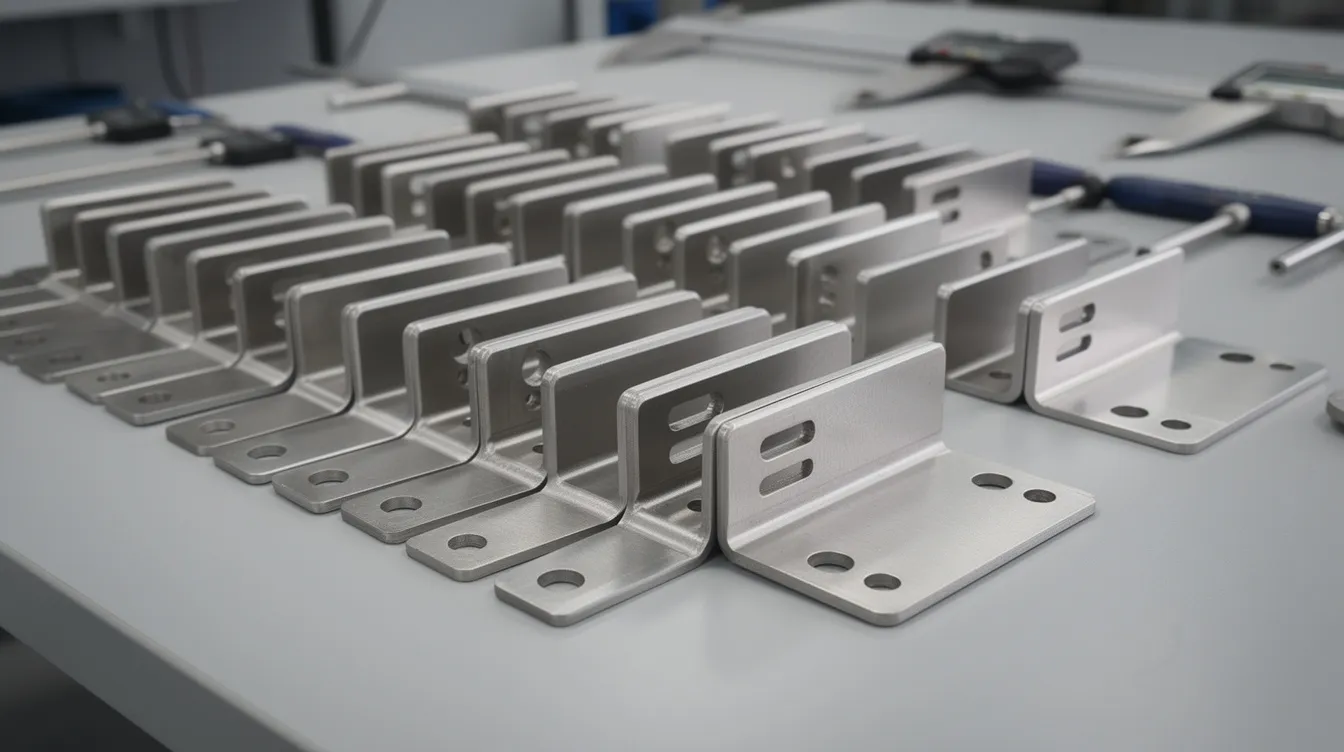
Applications of Bent Steel Sheet in OEM Products
Bent steel sheet appears in nearly every industry where a rigid, lightweight, and cost-effective structural form is needed. In automotive, bent steel forms brackets, chassis reinforcements, and battery enclosures for EVs. A battery tray that was previously a welded assembly of multiple plates can often be redesigned as a single bent steel box with folded flanges and formed stiffeners, reducing part count, weld distortion, and weight while improving structural rigidity. Such a tray might use 2–3 mm coated steel with dimensions of 400–600 mm × 300–400 mm.
In industrial machinery, bent steel produces guards, panels, frames, and covers that are mounted to equipment and must maintain position and shape under vibration. Electronics and server rack enclosures rely on bent stainless or mild steel for EMI shielding and structural integrity. Medical device frames use bent 304 stainless for its cleanability and corrosion resistance. Robotics applications demand precision mounting plates where holes, slots, and attached hardware must align within fractions of a millimeter, and bending can create complex components from a single material piece rather than assembling multiple machined parts.
Anebon regularly works with customers in Europe, North America, and Asia on these applications, handling both prototype quantities (10–50 pieces) and annual production runs of thousands. A representative example: producing an enclosure from 2 mm 304 stainless steel, approximately 500 × 400 × 150 mm, with flanged edges, multiple cutouts, tolerance of ±0.2 mm, ±1°, supplied with passivation finish and laid out for direct assembly. The point is that bending produces a finished, functional form from a single flat blank, which no other process can match for cost and flexibility at these volumes.
Summary & How to Request a Steel Bending Quote
This guide has covered the essentials of bending steel sheet for OEM production: selecting the right bending process (press brake air bending, bottoming, roll bending, or folding), choosing the correct material and thickness, applying DFM rules for bend radius and hole placement, managing springback, and controlling quality through inspection and process validation. Well-designed sheet metal bending reduces part count, weight, and overall project cost compared to machining from solid stock or welding multiple sub-assemblies.
When requesting a quote from Anebon, include the following: material grade (e.g., 304 stainless, mild steel, HSLA) and thickness, 2D or 3D part files with dimensions clearly noted, expected annual volume (prototype, small batch, or full production), surface finish and coating requirements, special tolerances for critical features, which surfaces are cosmetic, and whether the part requires secondary operations like welding, tapping, or hardware insertion. Finally, note your target lead time so Anebon can plan capacity accordingly.
We invite design engineers, R&D teams, and procurement managers to contact Anebon Metal Products Limited for DFM feedback and a fast quotation on your next bent steel sheet project. With more comments and questions, our engineering team is ready to help optimize your design for manufacture-reach out today to get started.