Master the Art: How to Bend Sheet Steel Effectively and Efficiently
Bend Sheet Steel: Practical Design & Manufacturing Guide for OEM Engineers
Introduction to Bending Sheet Steel
When you need brackets, enclosures, chassis, or panels for an OEM product, bending sheet steel is often the fastest and most cost-effective path from flat material to finished part. Sheet metal bending can produce parts from a single piece of material, preserving continuity that welding or riveting cannot match. The result is a lighter, stiffer component with fewer assembly steps and lower cost.
This article focuses on how to bend sheet steel in mild steel and common engineering steels from approximately 0.5 mm to 8 mm in thickness, with notes on thicker plate where relevant. You will learn the key concepts behind bend radius, material thickness, springback, and how laser cutting supports accurate metal bending on a press brake. Because bending sheet steel involves applying force to exceed the material yield strength and permanently deform it, understanding these variables is essential before you send a design to production.
Anebon Metal Products Limited is an ISO 9001:2015 and ISO 14001:2015 certified sheet metal manufacturer in Dongguan, China, serving overseas OEMs since 2010. Our facility integrates CNC laser cutting, press brake bending, CNC machining, die casting, and surface finishing under one roof. Sheet metal bending is faster than machining for thin-walled parts, and bending is cheaper than die casting for initial setups, making it the go-to bending process for most OEM sheet metal parts.
Basics of Sheet Metal Bending for Steel
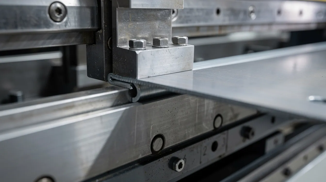
Sheet metal bending is the plastic deformation of flat sheet steel around a straight axis using tools such as a press brake or folding machine. The goal is to form a specified bend angle and inside radius without cracking, while holding dimensional tolerances. CNC bending can achieve accuracy levels of ±0.05 mm, making it a near-net-shape process that keeps material continuous-improving stiffness and fatigue life compared with welded seams.
Here are the key terms every engineer should know:
-
Inside bend radius – the radius on the concave face of the bend; controls outer-fiber stretch and cracking risk.
-
Outside radius – approximately inside radius plus two times material thickness.
-
Bend angle – the angle between the two flanges after forming (commonly 90°, but any angle is possible).
-
Leg (flange) length – measured from the bend line to the edge of each flange.
-
Bend line – the line on the flat blank where bending occurs; used to position holes, slots, and cut features.
-
Neutral axis – the internal locus where fibers neither stretch nor compress; its position through the thickness is described by the K-factor.
At Anebon, typical sheet metal fabrication in mild steel covers 0.6 mm to 6.0 mm on standard CNC press brakes. Thicker materials up to about 8 mm are handled with special tooling and larger machines.
Main Sheet Steel Bending Processes
Most bent parts at Anebon are parts produced on CNC press brake machines, with additional equipment like roll benders and folding machines where the shape demands it. Understanding each bending method helps engineers specify the right process for their design.
-
Air bending – the work piece contacts only the punch tip and the v die shoulders; air bending leaves a gap between the punch and die, meaning the sheet never fully conforms to the bottom tool. This requires lower bending force and offers flexible bend radii from a single v shaped die opening. A typical rule: set the v die width to 6–10 times the material thickness for mild steel. The trade-off is greater sensitivity to springback.
-
Bottom bending (bottoming) – the sheet is pressed until it contacts the full bottom die surface, producing less springback and tighter angle control. Bottoming requires higher force and a dedicated bottom tool matched to the target angle. Press brakes can exert forces over 100 tons for bending steel in this mode.
-
Coining – a high-pressure variant where the punch forces material into the die under extreme load, virtually eliminating springback. Coining demands 5–8 times the tonnage of air bending, increasing tooling wear. Anebon recommends coining only when angle tolerances tighter than ±0.25° are non-negotiable.
-
Roll bending – for producing large-radius curves or cylinders in sheet steel and plate. Using a mandrel can create smooth curved bends in sheet metal during roll forming operations.
-
Folding – suited for long, shallow bends on panels and doors where the fold length is large but the bend depth is small. Press brake bending is suitable for high-precision repeated production, while folding prioritizes speed on simpler geometry.
-
Rotary bending – rotary bending allows for angles sharper than 90 degrees without springback issues, and produces minimal tool marks on the surface. Stainless steel requires a press brake for bending at production scale, but rotary dies can be used with the brake for cosmetic parts.
When choosing a bending tool and method, consider your required angle tolerance, surface finish, production volume, and material type.
Material Considerations: Mild Steel and Other Sheet Steels
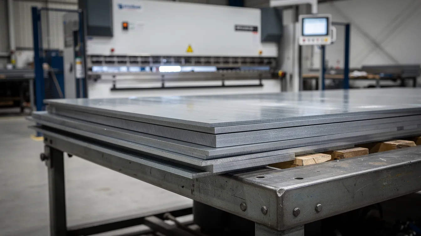
Mild steel-cold-rolled low-carbon grades like Q235, S235, SPCC, and A36 equivalents-is the most widely used material for bent sheet metal parts because of its ductility, low cost, and predictable forming behavior. Yield strength typically falls in the 200–250 MPa range, with elongation high enough to accommodate tight bends without cracking.
Higher-strength steels (500–800 MPa material yield strength) exhibit more springback, need larger bend radii, and carry higher risk of outer-fiber cracking. Thicker materials require larger bend radii, limiting design options. Minimum bend radius increases with material thickness and hardness.
Steel can be bent up to 20 mm thick with appropriate equipment, though for standard OEM sheet work, 0.5–8 mm is the practical range. Beyond sheet steel, other material types are common in OEM fabrication: aluminum has a high strength-to-weight ratio and bends easily with adjusted tooling; copper is highly conductive and easily bent for electrical applications; brass is known for its aesthetic appeal and machinability; and stainless steel springs back more than mild steel and requires careful radius selection. Galvanized steel has a zinc coating for corrosion resistance, but tight bends can crack the zinc layer.
For 0.5-in.-thick steel, longitudinal bending needs 3.75 times the material thickness as the inside radius. The following table summarizes recommended minimum inside bend radii for mild steel:
|
Thickness (mm) |
Minimum inside radius (across grain) |
Recommended safe radius |
|---|---|---|
|
1.0 |
1.0 × T (1.0 mm) |
1.0 × T (1.0 mm) |
|
2.0 |
1.0 × T (2.0 mm) |
1.25 × T (2.5 mm) |
|
3.0 |
1.0 × T (3.0 mm) |
1.5 × T (4.5 mm) |
|
5.0 |
1.0 × T (5.0 mm) |
1.5–2.0 × T (7.5–10 mm) |
After bending, Anebon can apply corrosion resistance finishes such as zinc plating, powder coating, or painting to extend the lifespan of bent sheet steel parts.
Bend Radius, Minimum Inside Radius & Springback
The inside radius is one of the most consequential decisions in any sheet steel bending design. If the radius is too small, the outer fibers stretch beyond their elongation limit and crack. If it is too large, the bend may lack the stiffness or geometry the design requires. A minimum inside bend radius of about 1 times material thickness is advisable for mild steel up to about 3 mm. For thicker or higher-strength steel, the internal bend radius should be at least 1 to 2 times the material thickness. Maintaining a minimum bend radius prevents cracks in sheet steel.
Springback is the elastic recovery that occurs when bending force is removed. Springback must be managed to achieve the desired final bend angle. Its magnitude depends on material yield strength, sheet thickness, the bend radius-to-thickness ratio, and the bending method used. Larger bend radii produce proportionally more springback because a greater fraction of the deformation remains elastic. Tooling impacts bend radius and required force during sheet metal bending.
Compensation methods used at Anebon include:
-
Overbending – overbending compensates for springback in sheet metal bending. For a nominal 90° bend in 2 mm mild steel using air bending, mild steel typically springs back about 2°. Program the CNC machine to bend to approximately 92°, so the part relaxes to the target 90° after unloading. The part is intentionally over bent, then settles to the correct angle.
-
Adjusted die angle – selecting an 88° punch and die set so the sheet is formed past 90° before release, producing less springback error.
-
Relieved dies – dies with reduced contact area near the bend nose to manage stress concentration and improve angular consistency.
-
Closed-loop CNC controls – angle feedback sensors on CNC press brakes measure each bend in real time and compensate automatically.
Anebon’s engineers maintain empirical data and past production records for different steels and tooling to achieve ±0.5° or better bend angle tolerance. CNC bending can achieve accuracy levels of ±0.05 mm on linear dimensions.
Grain Direction, Localized Stress & Hot Forming Options
Rolling imparts a grain direction to sheet steel. The orientation of the bend line relative to this grain significantly affects crack risk and achievable minimum radius.
Bending across the grain reduces the risk of cracking more than bending parallel. Transverse bending allows tighter inside radii without damage because the elongated grain fibers are more uniformly stressed. Conversely, bending parallel to the grain increases the risk of cracking-specifically, longitudinal bending may cause cracking on the outside radius where tensile strain is highest. However, bending with the grain requires less force than across it, which can matter for thicker materials.
Dos and don’ts for grain direction and edge preparation:
-
Do orient critical tight bends transverse to the rolling direction when possible.
-
Do keep the bend line at least 1.5–2 times the material thickness away from laser-cut or plasma-cut edges. These thermal processes can harden edges locally, reducing ductility.
-
Do lightly dress or grind heat-affected edges before bending if the bend line is close.
-
Do note that scoring an angle along the bend line allows for cleaner manual bends on prototypes or simple parts.
-
Don’t assume CAD default flat patterns account for grain direction-verify with the material supplier.
-
Don’t specify radii below proven minimums without running test bends first.
For most OEM sheet metal parts in 0.5–6.0 mm mild steel, Anebon forms cold on CNC press brakes and relies on correct tooling rather than hot forming. Hot forming becomes relevant for steel plate thicknesses of approximately 8–10 mm or greater, or when unusually tight radii are required. Pre-heating to 200–300 °C improves formability, while full hot forming at much higher temperatures is reserved for plate work beyond typical sheet metal scope.
Design for Manufacturability (DFM) for Bent Sheet Steel Parts
DFM means optimizing your part geometry so it can be bent accurately, repeatably, and at the lowest cost on production press brakes. Here is a practical checklist designers can apply immediately when modeling sheet metal in CAD.
Standardize radii. Use one or two consistent bend radii across the part and across related parts in an assembly. Fewer unique radii mean fewer tooling changes, less setup time, and lower cost.
Bend relief cuts. When a bend runs into an edge or another flange, include relief notches. Bend relief cuts prevent tearing when a bend is close to an edge. Bend relief notches should equal the material’s thickness in both width and depth to prevent tearing.
Minimum flange length. The length of flanges should follow minimum recommendations to avoid distortion. A safe guideline is that each leg should be at least 3–4 times the material thickness, or at minimum half the v die opening width, whichever is greater.
Feature placement. Preventing distortion requires keeping features away from bend lines. Holes should be placed at least 2.5 times the thickness from the bend edge. Holes should be at least 2.5 times the material thickness away from bend lines-if closer, they will distort during the bending process.
Clamping and handling. Clamping sheet steel between two solid pieces prevents surface damage during bending. Using softer materials when clamping prevents damage to the metal surface. Thin metal requires less clamping force to avoid bending at the wrong point.
Test bends. Test bends should be made before production to ensure accuracy, especially when using a new material type, thickness, or tooling combination.
Anebon’s engineers review customer CAD files as part of a DFM feedback service, suggesting bend radius changes, adding reliefs, and adjusting tolerances before production. This catches issues early in the forming sequence and avoids costly rework.
Dimensional Accuracy: Bend Allowance, Bend Deduction & K-Factor
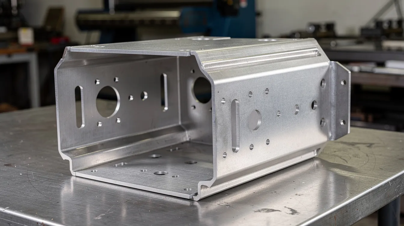
Flat pattern length for laser cutting must account for material stretching in bends. Bend allowance is critical for maintaining accurate dimensions in sheet metal fabrication. Using incorrect bend allowance values can lead to dimensional inaccuracies that cascade through the entire part.
Key definitions:
-
Bend allowance (BA) – the arc length along the neutral axis through the bend zone; added to the sum of flat sections when computing total blank length.
-
Bend deduction (BD) – the amount subtracted from the sum of flange lengths to determine blank length.
-
K-factor – the ratio that locates the neutral axis through the thickness, measured from the inside surface. For mild steel air bending on a press brake, K-factors often fall roughly between 0.3 and 0.5, with ~0.44 being a common starting point.
Numeric example: A part has two separate flanges of 50 mm each joined by a 90° bend in 2.0 mm mild steel with an inside radius of 2.0 mm (1.0 × T) and K = 0.44.
BA = (π / 180) × (Rᵢ + K × T) × bend angle BA = 0.01745 × (2.0 + 0.44 × 2.0) × 90 ≈ 4.52 mm
Total flat pattern length = 50 + 50 + 4.52 = 104.52 mm
Anebon’s CAM system uses empirically validated bend tables per material and thickness to generate accurate flat patterns. These tables are built from documented test bends, ensuring parts can be bent accurately to the intended dimensions without hand fitting or rework.
Role of Laser Cutting Before Bending
Anebon uses CNC laser cutting to prepare sheet metal blanks with precise edges, cutouts, and locating features before press brake forming. Accurate laser cutting directly improves bend location and repeatability because bend lines are referenced from consistent edges.
The combined advantage of laser cutting and press brake bending in a single facility:
-
Tight cutting tolerances of ±0.1 mm enable high-precision sheet metal parts after bending, especially on assemblies with mating components.
-
Automated process nesting reduces waste and lowers the overall cost of bent parts.
-
Tabs, slots, and locating features integrated into the flat pattern simplify fixturing and downstream assembly.
-
A single supplier controls the entire process from flat blank to finished bent part, eliminating alignment errors and shipping delays between separate vendors.
-
Material certificates, gauge verification, and quality checks happen under one roof, maintaining consistency from cut to bend to finish.
Typical Applications of Bent Sheet Steel in OEM Products
Bending increases stiffness with features like flanges, hems, ribs, and joggles, allowing thinner sheet metal to meet strength targets while reducing weight and material cost.
Common examples include:
-
Automotive brackets and mounting plates – multiple bends in 1.5–3 mm mild steel or HSLA, tight tolerances, zinc plating or e-coating for corrosion resistance.
-
Electronics enclosures and server racks – clean 90° bends in 1.0–2.0 mm cold-rolled steel, powder coated, with cable knockouts and ventilation features.
-
Medical device housings – thin materials (0.5–2 mm) with tight angular tolerances (±0.5°) and smooth edge finishes for safety.
-
Machinery guards and HVAC panels – larger parts up to 2,500 mm using flanges and folds for stiffness; sometimes louvers or embossed stiffeners are combined with bending to reduce part count.
Design choices in bend radius, material thickness, and finish directly impact cost and performance. For example, increasing radius to avoid finish cracking on galvanized parts, or adding a rib fold so that a thinner gauge can replace a heavier sheet, are common trade-offs Anebon’s engineers help OEMs evaluate.
Quality Assurance & Tolerances in Sheet Metal Bending
Anebon’s quality control approach for bent parts follows a structured process aligned with ISO 9001:2015:
-
First-article inspection (FAI) – a sample part is fully measured across all critical dimensions: leg lengths, bend angles, radii, and hole positions relative to bend lines.
-
In-process checks – bend angle verified mid-production with calibrated digital protractors and gauge blocks; backgauge positions confirmed per program.
-
Dimensional tolerances – mild steel bends are typically held to ±0.5–1.0° on angle and ±0.1–0.2 mm on linear dimensions under 100 mm.
-
Complex geometry verification – CMM or 3D scanning used where parts have multiple bends and tight form tolerances.
-
Material traceability – documented material certificates ensure thickness, tensile properties, and hardness are consistent lot-to-lot, keeping bending behavior stable.
Surface quality can be affected by worn tooling during bending operations, so Anebon tracks tool wear as part of preventive maintenance. Bending can leave indentations or scratches on the material, which is managed through appropriate die selection, protective films, and surface inspection before shipping. Anebon’s ISO 14001:2015 certification further ensures responsible handling of finish chemicals and waste.
Cost Drivers & Lead Time for Bent Sheet Steel Parts
The unit cost of a bent sheet steel part is driven by several factors:
-
Number of bends and radii variety – each unique radius requires a tool change; parts with multiple bends in varied radii increase setup time and labor costs.
-
Material thickness and strength – heavier gauge demands higher tonnage equipment and slower cycle times.
-
Tolerance tightness – holding ±0.5° on angle or ±0.1 mm on flange length may require bottoming instead of air bending, adding time.
-
Batch size – setup cost spread over a low-volume prototype run raises per-part cost significantly; in full production, that fixed cost is amortized and unit cost drops.
Simplification strategies that deliver lower cost include standardizing radii across parts, minimizing tool changes, and aligning bend directions to reduce repositioning. Early engagement with Anebon’s DFM team catches issues before tooling or large orders are committed.
Typical lead times: rapid prototypes can ship in days; production orders usually run two to four weeks depending on volume, finishing, and shipping. Bending can be performed on materials up to 20 mm thick, though thicker materials extend processing time.
How Anebon Supports Your Sheet Steel Bending Projects
Anebon integrates CNC laser cutting, CNC press brake bending, CNC machine operations, die casting, and surface finishing in a single facility. We specialize in overseas OEM projects from rapid prototypes to full-scale production, supporting materials like mild steel, stainless steel, and aluminum.
Our design consulting services include DFM feedback on bend radius, material thickness, tolerances, and stack-up issues before you commit to tooling or large orders. We produce custom precision sheet metal bending parts that meet the demanding requirements of aerospace, automotive, medical, electronics, and industrial machinery applications.
Ready to get started? Send your 3D CAD models and 2D drawings to Anebon’s engineering team for a detailed quotation and free manufacturability review. We will flag potential issues, suggest improvements, and help you achieve the best balance of cost, quality, and lead time for your bent sheet steel parts.