How to Work a CNC Machine: A Beginner’s Guide to Precision Machining
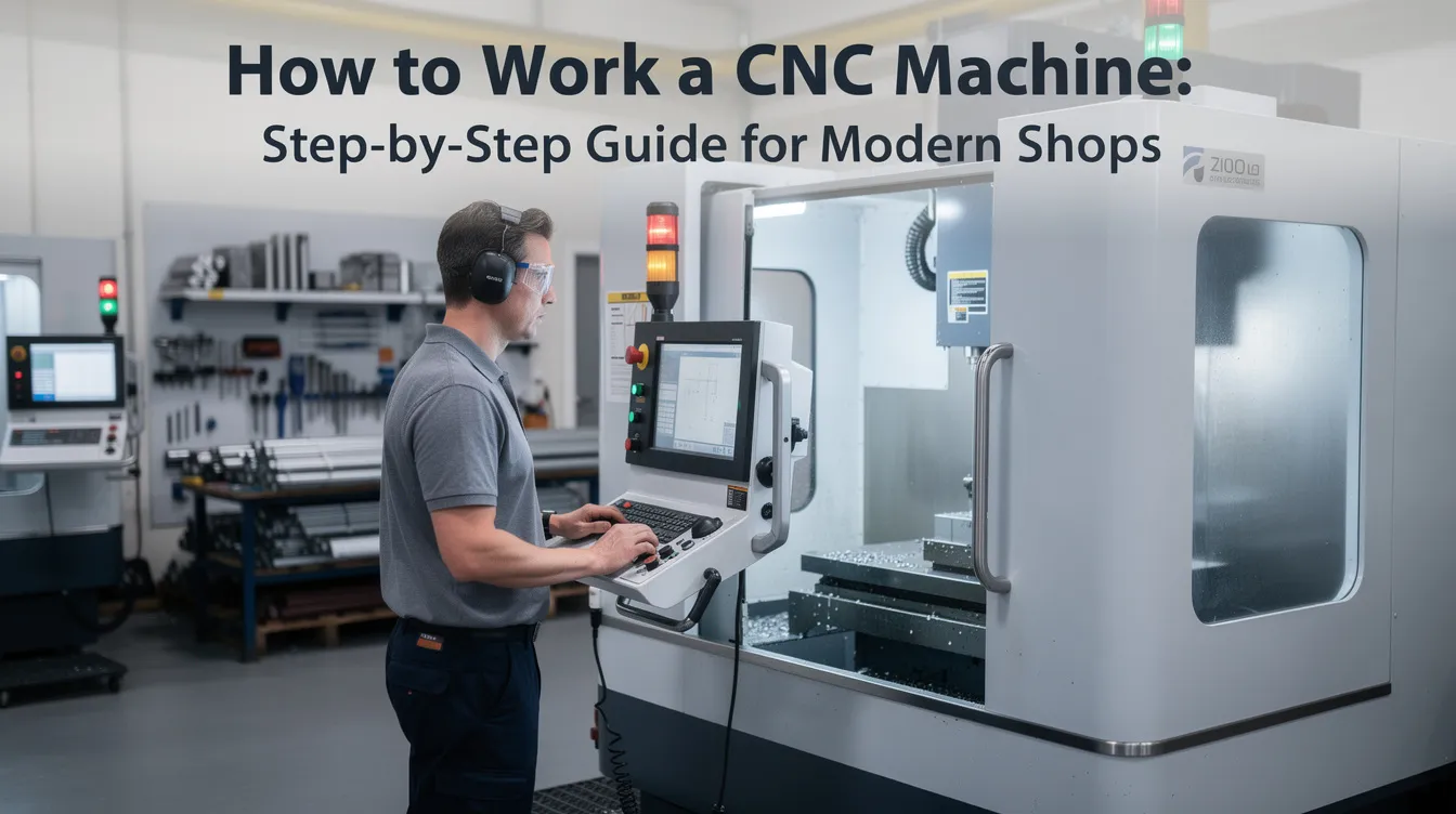
How to Work a CNC Machine: Step‑by‑Step Guide for Modern Shops
Whether you’re a design engineer stepping onto the production floor for the first time or a new operator preparing for your first supervised run, learning how to work a cnc machine is one of the most practical skills in modern manufacturing. This guide walks you through the entire process-from pre-start safety checks to running your first part-in a format you can reference right at the machine.
Overview: What You’ll Learn About CNC Operation
CNC stands for computer numerical control, a technology that has been around since the 1940s and now drives the majority of precision part production worldwide. A cnc machine uses computer-controlled tools to fabricate parts by moving axes automatically based on programmed instructions, replacing manual machining with hand wheels and physical labor. Common industrial examples include the cnc mill (vertical and horizontal), cnc lathes for cylindrical work, and cnc routers designed for cutting wood, plastic, and soft metals.
CNC milling machines are widely used for precision cutting across metals and plastics. CNC lathes are used for creating cylindrical parts with high precision. CNC machines can cut materials like metal, plastic, and wood, making them essential cnc machine tools in nearly every manufacturing industry.
What this article covers:
-
Pre-start safety checks and PPE requirements
-
Machine types, major components, and core terminology
-
The basic workflow from computer aided design through computer aided manufacturing to g code
-
Step-by-step machine setup for mills and lathes
-
Dry runs, first-part verification, and basic troubleshooting
-
Scaling to multi-axis production and when to partner with a professional service like Anebon Metal Products Limited
The instructions here apply broadly to 3-axis vertical cnc mills and turning machines used in OEM production. Where cnc processes differ for lathes, routers, or multi-axis centers, we note those differences. CNC machining can produce parts a hundred times faster than manual methods, and the cnc machining process includes five main steps: CAD modeling, CAM programming, machine setup, machining, and inspection. That process starts with creating a CAD model-and we cover every step after that below.
Core terms you will encounter throughout: computer aided design (CAD), computer aided manufacturing (CAM), g code, cutting tool, and work offsets. If any of these are new to you, the terminology section below will get you oriented.
Safety and Pre‑Start Checks Before Any CNC Operation
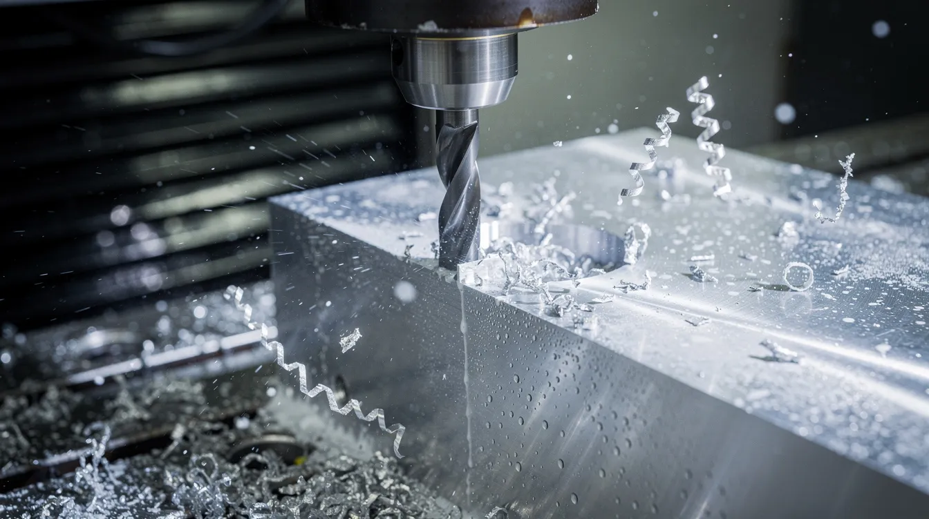
Safe cnc operation in 2026 still starts with disciplined pre-start checks-even on advanced machines equipped with guards, sensors, and interlocks. Adhering to safety protocols is crucial for safe CNC operation, and no amount of cnc technology replaces a methodical walk-around before hitting the green button.
-
PPE: Safety glasses (ANSI Z87.1 or equivalent), hearing protection in shops exceeding 85 dB, closed-toe safety shoes, and snug-fitting clothing. Remove loose jewelry, tie back hair, and never wear gloves near a rotating spindle.
-
Guards and interlocks: Verify that all machine doors close properly, emergency stop buttons are functional and within reach, and safety interlocks engage correctly on both mills and lathes.
-
Fluid levels: Check hydraulic oil, way lube, and coolant reservoirs against manufacturer ranges. For water-based coolant used when machining aluminum or steels, test concentration with a refractometer (typical 6–10 % range).
-
Air supply: Confirm shop air pressure is within 6–8 bar (90–115 psi) and filtration is clean-tool changers and pneumatic chucks rely on consistent pressure.
-
Coolant and ventilation: Proper venting or dust collection systems are needed when machining materials that emit fumes or dust. For plastics on cnc routers, dust extraction is especially important. An air blast system should be verified for chip clearing.
-
Housekeeping: Clear chips from previous jobs, remove forgotten tools or gauge blocks from the machine table or chuck, and wipe down touchscreens and control panels. Large stock must be securely clamped to the machine to avoid accidents-never leave unsecured material on a table.
-
Inspection of previous setup: Confirm no leftover fixtures, clamps, or measuring instruments remain in the work envelope.
Treat this list as a non-negotiable checklist. Print it, laminate it, and tape it to the side of the controller.
Understanding CNC Machines, Controls, and Core Terminology
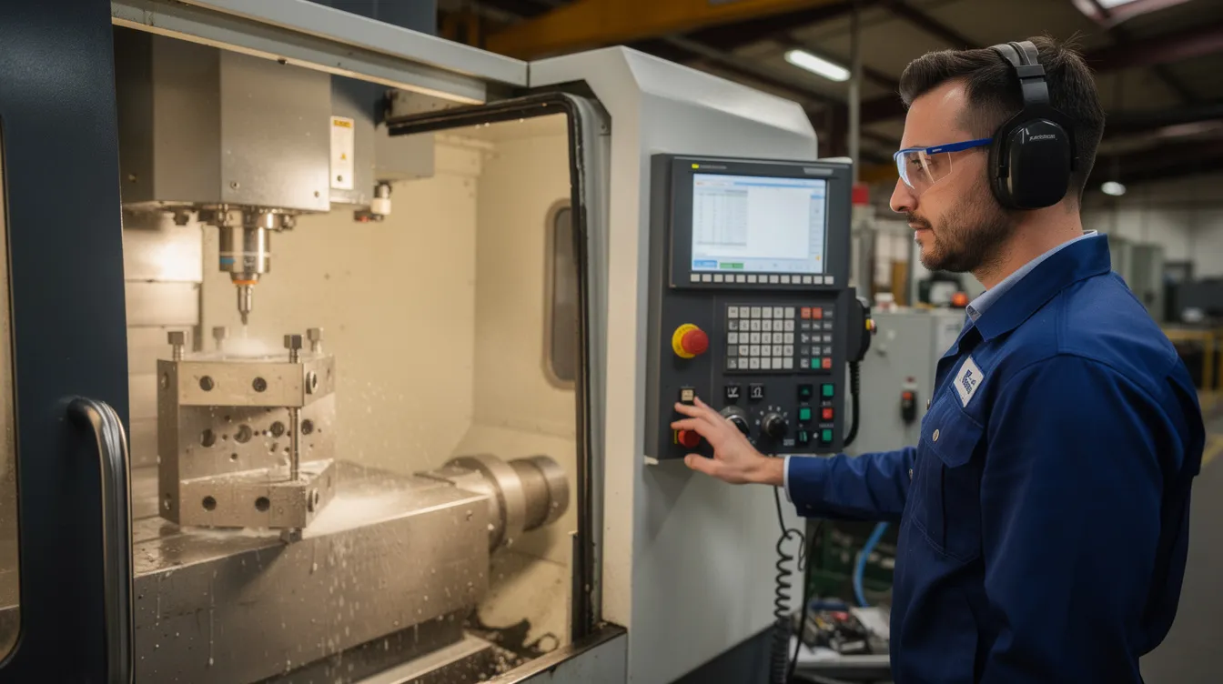
At its simplest, cnc machines operate by reading computer instructions (g code) and translating them into precise axis movements-x axis, y axis, z axis, and sometimes rotary axes-to remove material from a workpiece. Where a manual machinist turns hand wheels, the computer moves servo motors along ballscrews and linear guides with micron-level accuracy. G-code controls the movement and function of a CNC machine, and understanding machine controls and workholding is essential for cnc operation.
Key cnc machine types for OEM work:
-
Vertical CNC mill: Spindle oriented vertically; the machine table moves in X and Y while the spindle travels Z. The workhorse for pocketing, facing, and contouring.
-
Horizontal CNC mill: Spindle horizontal; superior chip evacuation for deep cavities and production runs.
-
CNC lathes (turning centers): Workpiece rotates in a chuck; tools in a turret move in X and Z. Multi-turret and swiss machines add live tooling and sub-spindles for complex parts.
-
CNC router: Lighter-duty, often used for plastics, composites, and soft metals on larger envelopes, sometimes with vacuum tables for flat sheet workholding.
-
CNC plasma cutters: Use high-temperature plasma cutting to cut conductive materials like steel plate.
-
CNC laser cutters: Can cut through various materials using laser beams for fine detail work.
-
Wire EDM: Uses an electrically charged wire to cut conductive materials with extreme precision, common for tool-and-die work.
Core vocabulary:
-
Workpiece: The raw stock material being machined into a finished part.
-
Cutting tool: End mills, drills, inserts, router bits-the tools that actually remove material.
-
Tool holder / collet / chuck: Devices that grip the cutting tool (in milling machines) or the workpiece (on lathes).
-
Fixture / vise: Workholding devices that secure the part on the machine table.
-
Work offset (e.g., G54): A stored coordinate that tells the controller where the part zero is located relative to machine zero.
-
Controller: The brain of the machine. Fanuc dominates globally at roughly 65 % market share, with Siemens Sinumerik, Haas, and Okuma as other major platforms.
Numerical control vs. distributed numerical control: Traditional numerical control ran one program on one machine. Modern shops use distributed numerical control (DNC), where cnc programs are pushed from a central server to many machines over a network-eliminating USB-stick errors and improving version control. Computer software on the server manages file revisions, so every specific machine on the floor runs the correct, approved program.
Anebon’s production floor uses multi-axis machining centers and turning centers with these same fundamental principles-just more axes and automation layered on top.
From CAD Design to CAM and G‑Code: Preparing Your CNC Project
Before any chip is cut, every cnc project follows a digital pipeline: cad design → cam software → g code. CNC machining combines precise digital preparation with careful physical setup, and getting this stage right prevents costly scrap later.
-
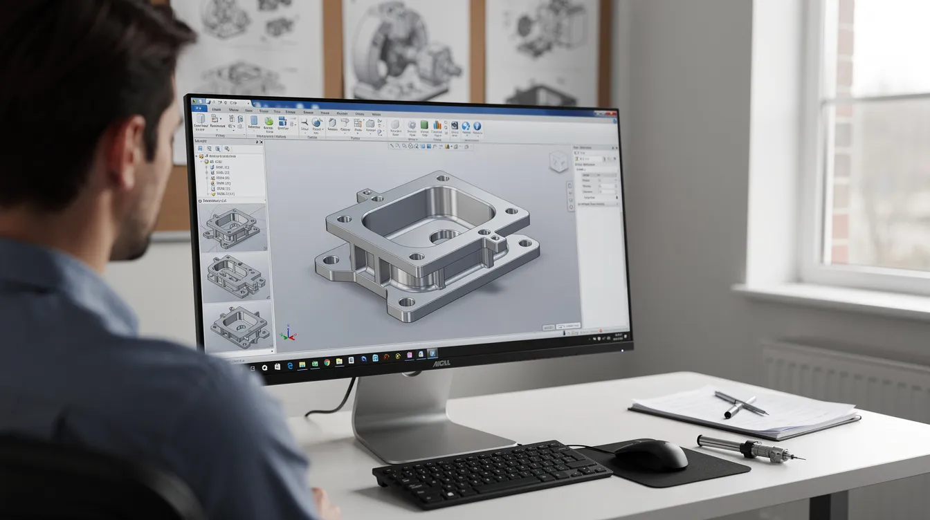
CAD step: An engineer creates a 3D model (using cad software such as SolidWorks, Fusion 360, CATIA, or common platforms like AutoCAD and Draftsight) with fully defined dimensions and tolerances. CAD software creates 2D and 3D models for CNC machining, and these cad files serve as the single source of truth for the part. Blueprint reading is essential for interpreting technical drawings and tolerances-the cad program must match the engineering intent captured in technical drawings.
-
CAM step: Cam software (Fusion 360 CAM, Mastercam, hyperMILL) takes the cad files and lets the programmer create toolpaths, select machining tools, and define cutting parameters. CAM software generates g code for CNC machines from CAD designs and automates cnc machining processes and toolpath generation. Familiarity with cad and cam software is essential for creating toolpaths that are safe, efficient, and collision-free.
-
Tool and material libraries: Professional cam software stores tool libraries and material databases-aluminum 6061-T6 at 800–1,200 SFM, stainless steel 304 at 40–80 SFM, titanium Ti-6Al-4V at 30–60 SFM-so the programmer selects appropriate tools and the software calculates spindle speed and feed rate automatically.
-
CAM workflow: Define stock geometry → select operations (facing, pocketing, drilling, finishing) → simulate toolpaths in the computer program → post-process to g code for the specific machine’s controller.
-
Version control and DNC delivery: In a professional shop, programs are version-controlled and delivered to machines via DNC rather than USB sticks, improving traceability and reducing human error. This is a form of computer aided machining workflow management.
-
DFM feedback: Anebon engineers routinely review customer CAD data and provide design-for-manufacturability feedback before finalizing CAM strategies-catching issues like impossible internal radii or unnecessary tight tolerances early, which directly reduces cost and lead time.
Real-world example: For an aluminum electronics housing in 6061-T6, the CAM programmer might select a ½-inch, 4-flute carbide end mill with a chip load of 0.004–0.008 in/tooth and RPM around 6,100–7,600, generating feed rates of 100–180 IPM for roughing. A stainless steel shaft in 304 would use entirely different parameters-SFM drops to 40–80, feeds slow dramatically, and tool coatings like TiAlN become critical.
Setting Up Tools and Workholding on a CNC Mill
Proper machine setup is the foundation of safe, accurate CNC machining-especially on vertical milling machines. Operators must understand different cutting tools and how to select them, and selecting the right cutting tools is key for effective machining. This section serves as a step-by-step checklist for a first supervised setup.
-
Select cutting tools based on the CAM tool list: face mill for surfacing, carbide end mills for pockets, drills and taps for holes, chamfer tools for edges. Choose appropriate tools for the material-2–3 flute end mills for aluminum, 4+ flutes for steel.
-
Load tools into the tool carousel or magazine according to the programmed tool numbers (T1, T2, etc.). Check gauge length, runout (should be under 0.01 mm for finishing), and correct tool holder type (ER collet, shrink fit, hydraulic).
-
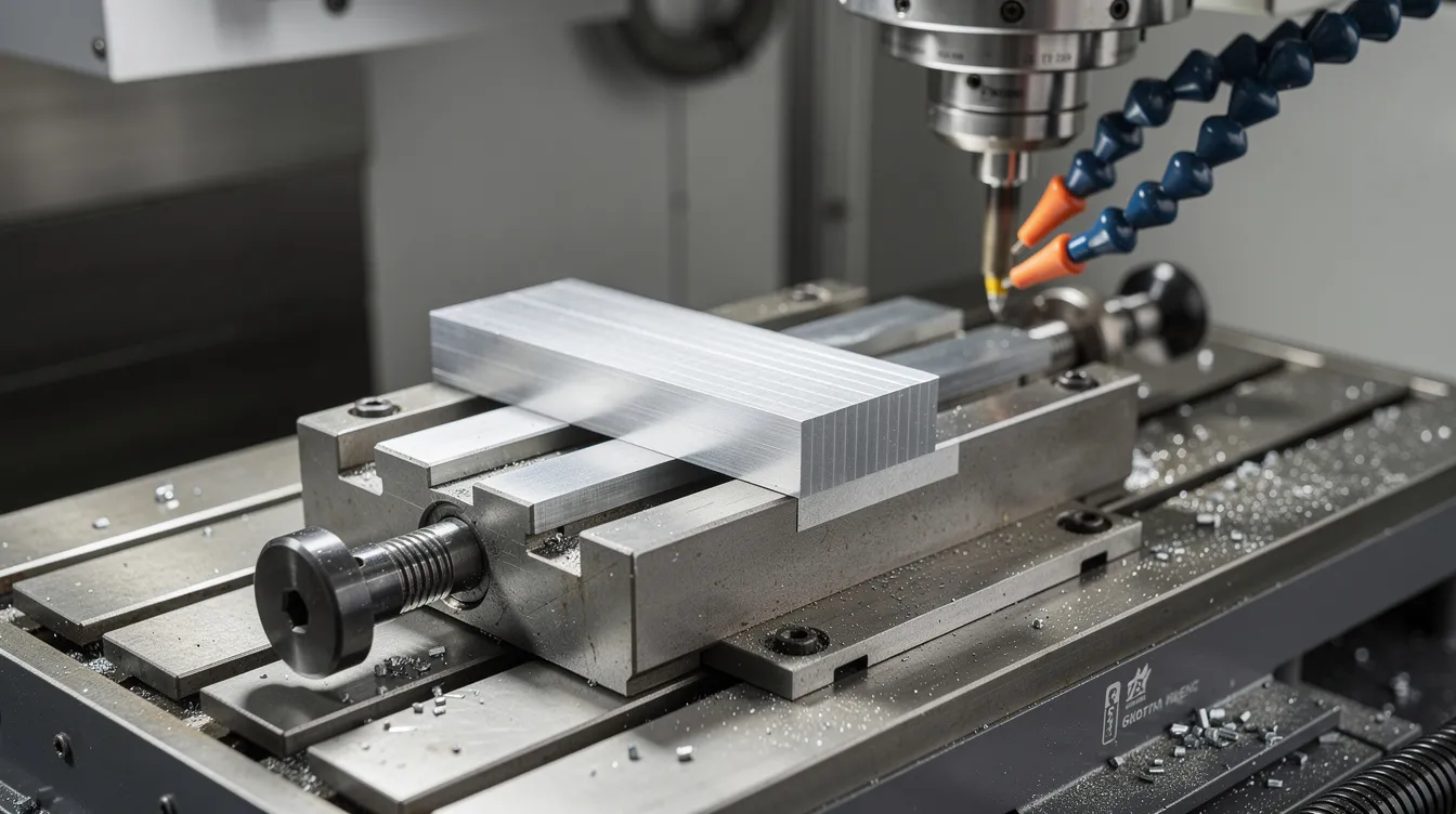
Mount workholding on the machine table: install a vise, fixture plate, or dedicated fixture, then tram or indicate to ensure the setup is square and level. Workholding secures raw material to prevent movement during machining.
-
Clamp the workpiece securely: correct jaw orientation, use of parallels or soft jaws, and verify that clamps and bolts are clear of programmed toolpaths. Securely clamping materials prevents accidents and defects in CNC machining.
-
Set tool length offsets: Use a tool setter probe or touch off manually on a known reference plane and store values in the tool length offset table. Accurate tool length data is critical-errors here translate directly to Z-axis dimensional errors on the part.
-
Set work offset (e.g., G54): Jog the spindle to the defined X, Y, and Z origin on the stock material or fixture. Setting zero points defines the x axis, y axis, and z axis origin on the machine. Manually jogging the machine establishes zero points for accurate machining. Write these coordinates into the work offset page.
-
Clearance check: Jog around the part at safe Z height to ensure no collision risk with fixtures, clamps, or the machine enclosure. Watch for tool wear monitors or probes that may protrude.
For parts requiring tight tolerances (±0.005 mm or tighter), consider a spindle warm-up before setting tool offsets-thermal growth in a cold spindle can shift measurements.
Setting Up Tools and Workholding on a CNC Lathe
On a CNC lathe, the workpiece rotates and the cutting tool remains stationary in the turret-the opposite of a mill. This changes workholding, offset procedures, and safety considerations. Understanding how a cnc machine works in a turning context is essential for producing shafts, bushings, threaded parts, and other machine parts.
-
Chuck or collet system: Install and align the chuck, checking jaw condition and runout. For precision turned components, jaw runout should be under 0.01 mm. Collets offer better concentricity for smaller bar stock.
-
Load turning tools: Install turning inserts, boring bars, grooving tools, and parting tools into turret stations. Assign each station to a tool number matching the cnc programs. Verify stick-out to avoid interference with the tailstock or steady rest.
-
Set tool geometry offsets: Use a tool eye or manual touch off on the part OD and face. Record X and Z offsets for each tool in the offset page. Nose radius compensation values must match the actual insert.
-
Workholding setup: Grip raw bar or saw-cut blanks to a specified length, ensuring adequate grip length (general rule: grip at least 1× the diameter). Use a tailstock or steady rest for long or slender parts to prevent vibration.
-
Work coordinate system: Set Z0 at the finished face and X0 on the spindle centerline-these must match what was programmed in CAM.
-
Typical first operations: Facing, OD roughing, OD finishing, drilling on center, and parting-off. These cover the majority of common OEM metal parts.
-
Speed and clamping limits: Confirm chuck speed limits and clamping force before starting. Long parts with excessive stick-out can whip dangerously at high RPM.
CNC machinists oversee CNC machinery operations on both mills and lathes. They must interpret technical drawings and specifications, and they require hands-on training for proficiency. CNC machinists work in industries like aerospace and automotive, where ability to interpret engineering drawings is crucial for every cnc operator on the floor. Even the toughest materials-titanium, Inconel-follow these same setup fundamentals, just with more conservative parameters.
Powering Up the CNC Machine and Loading Programs
Standard start-up sequences on modern CNC machining centers and turning centers follow a predictable pattern. Regular maintenance ensures consistent precision in CNC machines, and the power-up routine is your first chance to catch anomalies.
-
Main power-on: Turn on the cabinet breaker, then use the control panel to boot the CNC controller. Watch for initialization messages, alarm clears, and axis homing prompts.
-
Home all axes: Execute the homing sequence so the control knows exact machine zero positions for every axis (X, Y, Z, and any rotary axes) before any jog or tool change.
-
Load the cnc program: Transfer from a USB drive, network share, or DNC system. Check program revision number and filename against the setup sheet-wrong revision is a common source of scrap.
-
Verify program details: On the control, confirm correct work offset (G54 vs. G55), correct tool numbers, and set spindle speed and feed overrides to conservative values (80–100 %) for the first run.
-
Setup sheet: Display or print the setup sheet that lists tooling, workholding, and special notes. Confirm the machine matches that sheet before proceeding. To use a cnc machine effectively, the physical setup must mirror the digital plan exactly.
-
Spindle warm-up: If the machine has been idle, run a warm-up cycle (10–20 minutes of progressive spindle speeds) to stabilize thermal conditions. This is especially important for shops holding tolerances under ±0.01 mm.
Dry Runs, Single‑Block, and First Part Machining
The first part is never run at full speed in a professional cnc operation. A dry run or simulation should be performed before machining any new program. This verification step saves machines, tools, and material-and is standard practice in ISO-certified shops.
-
Dry run (air cut): Temporarily adjust the Z work offset upward by 25–50 mm (1–2 inches) so the tool cuts air instead of stock material. Run the entire program to verify motion, tool changes, and clearances.
-
Single-block mode: Step through the program line by line using single-block, feed hold, and optional stop functions. This lets you watch each machine move individually during the first proofing run.
-
Operator vigilance: Keep one hand near the emergency stop or feed hold. Operators must closely monitor CNC machinery during the first few passes, watching for clearance issues around clamps, fixtures, and internal components. CNC machinists conduct test runs to ensure proper machine operation.
-
First actual cut: Run at reduced feed override (50–70 %) and listen for abnormal cutting sounds, chatter, or spindle load spikes. Identifying and resolving issues during machining is an important operator skill.
-
In-process inspection: Measure critical dimensions with calipers and micrometers, check surface finish visually and with a profilometer if required, and compare measurements to the drawing.
-
Adjustments: Update tool wear offsets, tool length offsets, or cutter radius compensation (G41/G42) to bring part measurements into tolerance. CNC machining reduces manufacturing costs by minimizing production times-but only when the first article is right.
Basic G‑Code and Controller Functions Every Operator Should Know
Most modern cnc machinists don’t write g code from scratch-cam software handles that. But familiarity with g-code and M-code is important for reading and editing programming code, and basic g-code understanding allows operators to troubleshoot and adjust programs on the fly. G-code is the programming language used in CNC machining, and operators need strong technical knowledge and practical shop skills for CNC work.
-
Motion codes: G0 (rapid positioning-no cutting), G1 (linear cutting feed), G2/G3 (clockwise/counterclockwise circular interpolation), and plane selection codes G17 (XY), G18 (XZ), G19 (YZ) for milling.
-
Work and tool compensation: G54–G59 (work offsets), G43 (tool length compensation), G41/G42 (cutter radius compensation left/right), G40 and G49 (cancel compensation).
-
M-codes: M3/M4 (spindle on CW/CCW), M5 (spindle stop), M7 (mist coolant), M8 (flood coolant), M9 (coolant off), M30 (program end and rewind). On lathes, additional M-codes control chuck open/close and tailstock. Spindle control is managed through these commands.
-
Controller features: Program edit vs. memory mode, graphics/simulation mode for verifying cnc programs on-screen, offset pages for tool and work data, tool life management counters, and alarm messages that diagnose faults.
-
Modal state awareness: Learn to read the active g-code modal state on the control screen. If you restart a program mid-cycle, knowing which G-modes and M-modes are active prevents dangerous unexpected moves.
Certification programs can help in gaining competencies in CNC operations. Many machine tool distributors and community colleges offer controller-specific training courses worth the investment.
Scaling Up: Multi‑Axis CNC, DNC, and Production Best Practices
The fundamentals above apply whether you’re running a simple 3-axis cnc mill or a 5-axis CNC machining center producing complex parts for aerospace or the medical industries. The difference is scale and complexity.
-
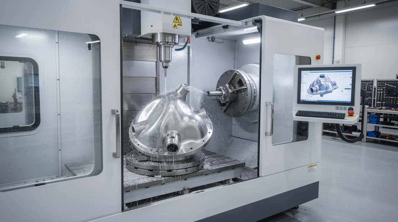
Multi-axis machining: 4-axis indexing and 5-axis simultaneous machining reduce the number of setups by allowing access to multiple faces of a part in a single clamping. This improves accuracy, reduces cycle time, and enables geometries impossible on 3-axis machines.
-
Typical applications: Aerospace brackets, medical implants, and complex housings manufactured at facilities like Anebon in Dongguan, China.
-
DNC in production: Programs are managed centrally and pushed to many machines from a central server, ensuring every operator runs the correct revision. This is essential when dozens of machines run concurrently.
-
Production best practices: Standardized tooling cribs, documented setup sheets, in-process inspection plans, SPC data collection (Cpk tracking), and preventive maintenance schedules.
-
Quality and certification: ISO 9001:2015 and ISO 14001:2015 provide frameworks for managing large cnc machining operations. CNC machining ensures all parts are produced with high consistency, and CNC machines can work with a wide range of materials-from aluminum to titanium to engineering plastics-under controlled, documented processes.
-
Data-driven improvements: Modern manufacturing facilities track cycle times, machine utilization, and tool wear patterns to continuously optimize throughput and machining cost.
Common Beginner Mistakes and How to Avoid Them
Even experienced engineers new to cnc operation face recurring pitfalls. Here are the most common ones and how to avoid them.
-
Insufficient workholding: Not tightening the vise or chuck fully, or using inadequate clamping force. Parts shift mid-cut, destroying the workpiece and potentially the cutting tool.
-
Wrong work offset: If G54 is mis-set or the wrong offset is called, the machine cuts in the wrong location. Double-check every offset entry before running.
-
Unit mismatch: Mixing metric and imperial units between cam software and the controller. A 1.000-inch move interpreted as 1.000 mm is a guaranteed crash.
-
Excessive tool stick-out: Long tool stick-out causes deflection and chatter. Keep tools as short as possible while maintaining clearance.
-
Bad feeds and speeds: Optimizing speeds and feeds prevents tool failure and increases efficiency. Cutting speeds and feeds should match the material being machined-too aggressive breaks tools, too conservative causes rubbing, heat buildup, and work hardening in stainless steels. Knowledge of trigonometry and algebra is necessary for calculating feeds and speeds when working outside pre-set cam software parameters.
-
Skipping first-article inspection: Skill in using measuring tools is required for verifying part dimensions. Inspection tools include calipers, micrometers, and Coordinate Measuring Machines. Never assume the first part is good-measure it.
-
No simulation or dry run: Always run simulation in cam software, verify graphically on the controller, and perform a dry run before cutting material.
Countermeasures:
-
Use checklists for every machine setup
-
Run simulations in cam software before posting g code
-
Perform a dry run on every new program
-
Log lessons learned after every cnc project for future reference
-
Pair new operators with experienced cnc machinists during training
When to Partner with a Professional CNC Machining Service
Many overseas OEMs and design teams choose to outsource CNC machining when projects involve tight tolerances, complex geometries, or fast lead times that exceed in-house capability.
-
Scenarios for outsourcing: 5-axis machining of aerospace brackets, medical prototypes needing ±0.002 mm tolerance, or multi-process builds involving die casting and CNC finishing. CNC machining allows for precision on a micro level that may require specialized equipment to achieve.
-
Advantages of an ISO-certified partner: Anebon Metal Products Limited, based in Dongguan, China, provides access to multiple CNC machines-mills, lathes, 5-axis centers-along with materials from aluminum and titanium to plastics, and integrated quality assurance with CMM inspection.
-
Full lifecycle support: Anebon supports rapid prototyping through bridge production to full-scale OEM manufacturing, including surface treatments (anodizing, plating, powder coating) and final inspection reports.
-
DFM feedback on demand: Design engineers can send cad files directly for DFM feedback, CAM strategy suggestions, and a detailed quote-reducing the trial-and-error involved in learning cnc operation alone.
Key Takeaways for Learning How to Work a CNC Machine
Mastering how to work a cnc machine means understanding the complete workflow-CAD → CAM → setup → verification → production-not memorizing every g code. The machining process is systematic, and following it consistently produces consistent results.
-
Safety first: Rigorous pre-start checks and PPE compliance are non-negotiable, regardless of experience level.
-
Accurate offsets: Correct tool length, tool wear, and work offsets are the single biggest factor in part accuracy. Measure twice, cut once.
-
Simulate and dry-run: Always simulate new cnc programs in cam software and run a dry cut on the machine before committing to stock material.
-
Measure first-off parts: Use calibrated inspection tools to verify the first article against the drawing before running production.
-
Keep learning: CNC technology evolves-multi-axis machines, automation, digital twins, and AI-assisted toolpath optimization are reshaping the manufacturing industry. Invest in training and stay current.
CNC machines are powerful tools for OEM manufacturing across aerospace, automotive, medical, electronics, and robotics when run by trained operators following clear procedures. Whether you’re cutting aluminum housings on a 3-axis mill or turning titanium shafts on a multi-turret lathe, the fundamentals in this guide apply.
If you need production-ready metal parts rather than just training, contact Anebon Metal Products Limited for professional CNC machining, turning, 5-axis work, die casting, and sheet metal fabrication. Send your CAD files for a free DFM review and quote.