How to Eliminate Flash Defects and Reduce Finishing Costs in Die Casting Production
Introduction: Why Flash is So Expensive in Die Casting
Die casting is a widely used manufacturing process for producing complex metal parts at scale, yet one of the most persistent and costly problems on the shop floor is flash. Flash occurs when excess molten metal escapes from the die during injection, forming thin fins or ridges along parting lines, ejector pins, and slider interfaces. It can lead to unnecessary waste and increased production costs that erode margins across entire programs.
For OEMs in the automotive industry, electronics, and industrial machinery, flash is often the single largest driver of secondary finishing costs. Flash removal can consume 15–30% of total cycle time in high-volume programs, and manual deburring typically adds $0.50 to $3.00 per aluminum die casting. Those numbers compound fast when you’re running 50,000 to 500,000 parts per year. Flash is closely related to other common die casting defects like porosity, cold shuts, and flow marks, but unlike those internal issues, flash is immediately visible on every casting surface and directly drives trimming labor.
Anebon Metal Products Limited, as an ISO 9001:2015 and ISO 14001:2015 certified die casting and CNC machining partner founded in 2010 in Dongguan, China, systematically targets flash reduction through die design, process control, and in-line inspection. This article delivers practical, shop-floor-level actions that process engineers and OEM purchasers can apply immediately to cut flash and finishing costs.
Understanding Flash: How and Where It Forms in the Die Casting Process
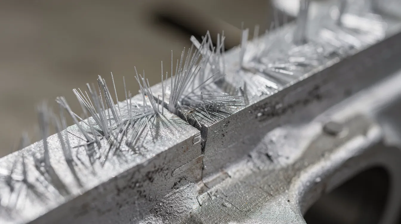
In the die casting process, flash is the thin, unwanted fin of metal that forms wherever molten metal fills gaps between mating die components. Flash can create thin protrusions along the junction of die cast parts-at the parting line between die halves, around ejector pins and bushings, at core and slider interfaces, and at overflow and gate transitions. Flash forms from excess molten metal escaping the die cavity under high pressure.
The basic physics are straightforward. Molten metal is injected at pressures ranging from 40 to 140 MPa during filling and intensification. Any clearance between die components-even a few hundredths of a millimeter-becomes a leak path. When the separating force from injection pressure exceeds the sealing capability of the mold cavity surfaces, metal escapes and solidifies as flash.
Flash is distinct from other casting defects. It is external and visible on the casting surface, whereas gas porosity results from trapped air or gases in the metal, cold shuts occur when molten metal streams fail to merge properly, and misruns occur when molten metal does not completely fill the mold. Small, controlled flash may be tolerable in non-critical areas of some aluminum die casting applications, but uncontrolled flash increases trimming time, accelerates tool wear, and risks dimensional non-conformance on sealing and mating surfaces.
Where to inspect for flash on actual castings:
-
Parting line seams around the full perimeter
-
Ejector pin faces and bushing interfaces
-
Slide and core shut-off surfaces
-
Gate and overflow transitions
-
Any cosmetic or sealing surface crossed by a parting line
A typical A380 aluminum electronics housing, for example, may show visible lines of flash at the lid parting line and gate remnants that require 40–60 seconds of extra grinding per piece.
Root Causes of Flash in High Pressure Die Casting
Flash is usually a symptom of multiple interacting factors across die design, machine capability, die wear, and injection parameters. A structured root-cause analysis using 5-Why or Ishikawa methods is far more effective than simply lowering metal temperature or grinding die surfaces harder, which often trades flash for cold shuts and incomplete filling.
Primary root cause categories and diagnostic clues:
-
Inadequate machine tonnage: Flash appearing uniformly around the entire parting line-especially worse opposite the injection side-suggests the machine’s proper clamping force is at or below the separating force threshold. Errors in projected area calculations (omitting runner and overflow areas) frequently lead to under-specified tonnage.
-
Improper die design: Flash concentrated near specific inserts, sliders, or cores points to insufficient shut-off land lengths or poor sealing geometry. Porosity affects about 30% of aluminum die casting batches, and attempts to fix porosity by altering gate positions can inadvertently redirect pressure toward weak shut-off areas.
-
Die wear and damage: Flash formation is caused by worn or misaligned die surfaces. Shut-off land edges round over tens of thousands of shots, slide gibs wear, and ejector pin bushings loosen. Flash that worsens progressively over weeks or increasing shot counts is the hallmark of wear-related leakage.
-
Thermal expansion and die temperature imbalance: Uneven cooling systems cause differential thermal expansion between die components. Cold dies at start-up leak more broadly; after long runs, thermal growth and loss of parallelism cause localized flash and warpage due to thermal stress and thermal fatigue.
-
Incorrect process parameters: Excessive injection pressure can lead to flash defects, particularly during intensification. Over-packing after cavity fill generates pressure spikes that force the die halves apart. Conversely, insufficient pressure causes misruns and surface defects.
-
Alloy and material issues: Higher-fluidity alloys or contaminated raw materials change metal flow behavior. If flash correlates with a new batch of casting material, melt cleanliness is suspect.
Start-up vs. steady-state behavior: More flash when the die is cold indicates insufficient sealing before thermal expansion brings surfaces into contact. More flash after extended runs points to thermal growth exceeding design allowances, or accumulated die surface erosion.
Die Design Strategies to Prevent Flash Before It Starts
Die design is the most powerful lever for eliminating flash and other common defects long before the production process launches. Designing for manufacturability directly impacts flash severity, and mold design optimization can reduce defect rates by over 40%.
Parting line selection:
-
Choose parting lines that create simple, continuous sealing surfaces
-
Avoid crossing thin ribs or features that are difficult to clamp tightly
-
Minimize sharp steps that concentrate stress and create leak paths at complex geometries
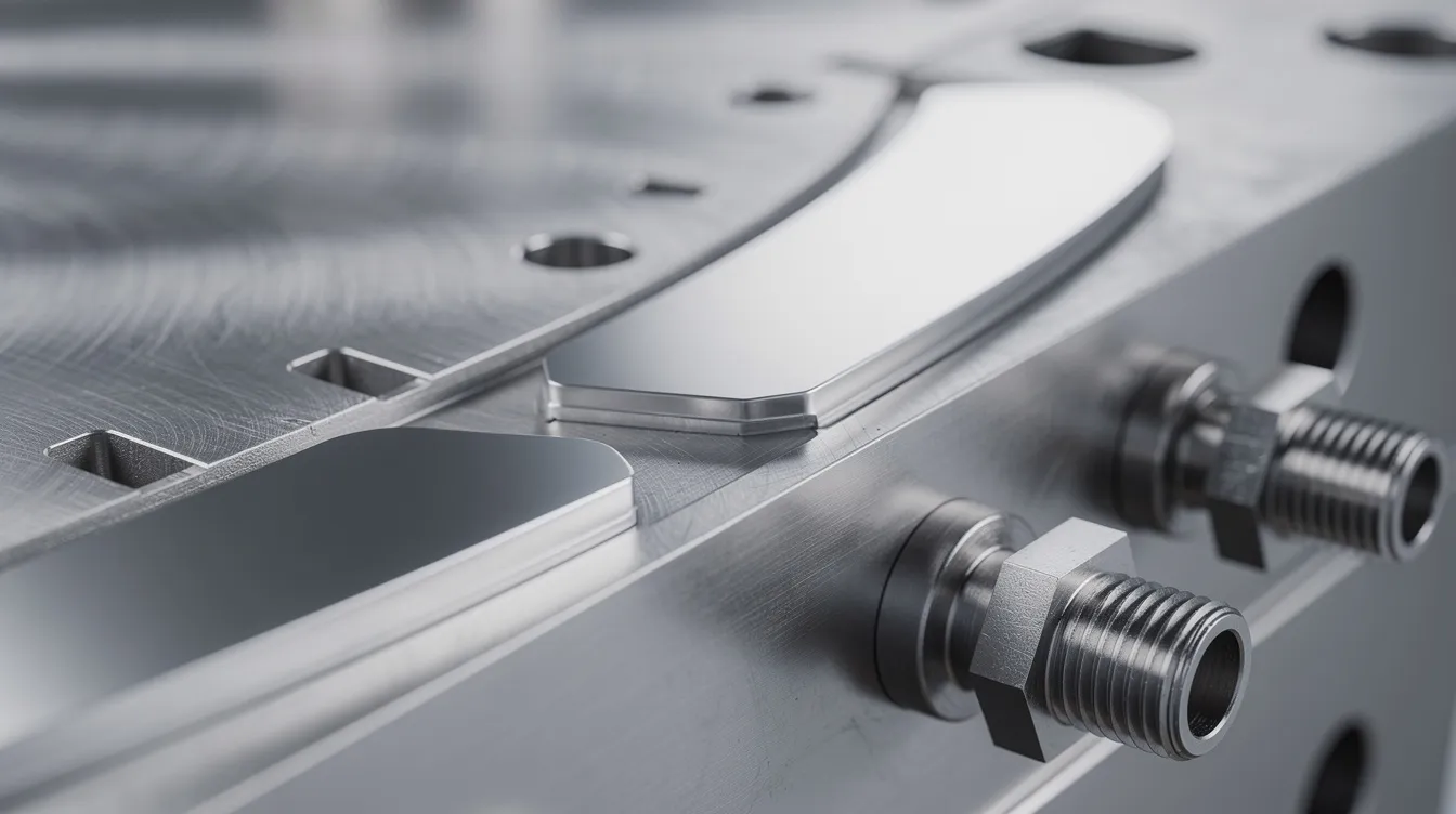
Shut-off surface design:
-
Use generous land lengths (1.5–3 mm depending on die material hardness and alloy)
-
Specify proper angles and uniform contact pressure on slides, cores, and inserts
-
Define tolerances for flatness and perpendicularity at operating temperature, not room temperature-account for 0.02–0.05 mm per 100 mm of thermal expansion
Venting and overflow design:
-
Proper venting in molds prevents gas-related defects like porosity. Proper venting can reduce gas-related defects by 30%, and sufficient vent depth (0.02–0.05 mm for aluminum) prevents gas entrapment without creating flash
-
Position overflows to avoid forcing metal toward weak shut-off areas
-
Incorporate venting systems that exhaust trapped air before the metal front arrives, preventing poor venting conditions that cause trapped gases and gas porosity
Gate and wall thickness optimization:
-
Optimizing gate design can significantly enhance die casting quality. Multiple small gates in mold design reduce turbulence-related defects compared to single large gates
-
Maintaining adequate wall thickness (2.0–3.0 mm for most aluminum parts) prevents uneven cooling and die failure. Maintain uniform wall thickness with transition ratios no greater than 2:1
-
Mold design directly influences metal flow patterns and cooling rates
Simulation and DFM:
-
Utilizing Computer Aided Engineering tools can identify potential flash points before molding. Run flow simulation and thermal analysis to visualize high-pressure paths and predict where metal might escape
-
Cooling channel placement must ensure uniform temperature distribution across the die
Anebon’s DFM feedback and precision machining expertise often suggests minor geometry changes-fillets, draft optimization, wall redistribution-that reduce die complexity and sealing line length, lowering flash risk and trimming time before tooling is cut.
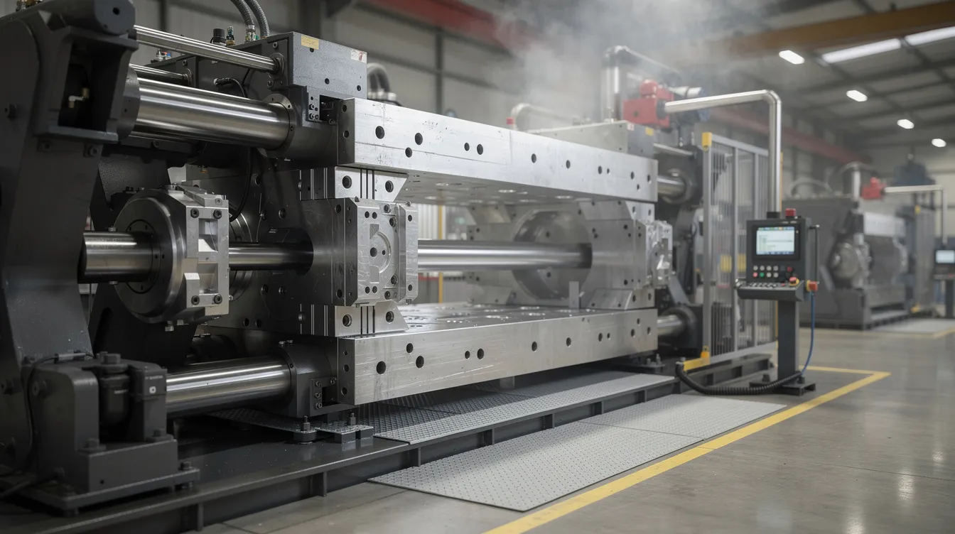
Clamping Force, Alignment, and Machine Capability
Even a perfectly designed die will flash if clamping force is inadequate or platen alignment is off. This is one of the most straightforward areas to diagnose and correct.
-
Calculating required locking force: Multiply the projected area of the casting (including runners and overflows) by cavity injection pressure (typically 40–70 MPa for aluminum die casting) and apply a 10–20% safety factor. For example, an 800 cm² projected area at 50 MPa requires at least 44,000–48,000 kN of clamp force to prevent die opening.
-
Symptoms of insufficient tonnage: Flash consistently around the entire parting line, worsening at peak injection pressure, especially on the side opposite the injection point. This indicates the machine cannot hold the die halves together against internal separating force.
-
Platen and tie-bar alignment: Misalignment results in localized flash on one corner or along one edge. Use feeler gauges, dial indicators, or tie-bar strain gauges to verify even clamping across all four corners. Blue-checking shut-off surfaces at each maintenance interval reveals uneven contact.
-
Machine selection: Match die size and projected area to machine tie-bar spacing and maximum tonnage. Run tools at 70–85% of maximum clamp force to leave margin for wear, thermal drift, and process variation. Avoid running consistently at maximum capacity.
-
Vacuum assisted casting: Vacuum systems can improve filling and reduce turbulence leading to flash by evacuating trapped air from the mold cavity before and during injection, reducing the internal pressure that contributes to die separation.
Anebon regularly reviews OEE and flash scrap data by machine to identify presses that need mechanical service, calibration, or reassignment of tools to higher-capacity equipment for better cost efficiency.
Optimizing Process Parameters to Minimize Flash Without Creating Other Defects
Chasing flash purely by reducing injection pressure or metal temperature easily triggers other casting defects. The goal is balanced process parameters that deliver casting quality without excessive die loading.
Injection speed and pressure:
-
Injection speeds between 3–5 m/s optimize filling without turbulence. Excessively high second-stage speed or excessive pressure increases die-opening force and creates leak paths
-
Use shot profiles with controlled first-stage slow fill (to clear runners without turbulence), optimized fast second-stage fill, and appropriate intensification hold time
-
Monitor the pressure curve at the transition between fill and pack-spikes here are where flash typically originates
Melt temperature and die temperature:
-
Optimal aluminum die casting temperatures range from 620 to 700°C (A380 typically 620–650°C). High melt temperature lowers viscosity and raises flash risk; low metal temperature increases cold shuts and incomplete filling risks
-
Adjusting metal temperatures within the correct window can cut rejection rates by over 40%
-
Maintaining die temperatures between 200–250°C reduces crack formation by 60% and provides stable sealing under temperature control. Non-uniform die temperature creates local gaps due to differential thermal expansion, leading to localized flash
Process monitoring:
-
Apply statistical process control on key injection parameters: metal temperature, die temperature, injection speed, and intensification pressure
-
Detect drifts before flash becomes visible on parts by setting control chart alarms on critical variables
-
Track when molten metal fills the cavity relative to solidification onset-the window between fill completion and gate freeze determines how long the die is exposed to maximum internal pressure
Numeric example: In one production setup running A380 on a 900-ton press, reducing intensification pressure from 120 MPa to 100 MPa while slightly increasing gate size and maintaining shut-off land flatness within 0.02 mm reduced flash height from 0.3–0.4 mm to under 0.15 mm-cutting finishing time by roughly 30% without any loss in structural integrity or fill quality. This kind of balance prevents the scenario where engineers solve flash but cause molten metal fail conditions such as short shots or weak mechanical properties in the die cast part.
Die Wear, Maintenance, and Tooling Life Management
Progressive die wear is one of the most common reasons flash defects gradually increase over months in aluminum die casting production. Regular die maintenance can minimize flash defects in casting and extend overall tool life.
Wear mechanisms affecting flash:
-
Erosion and rounding of shut-off lands from high-velocity metal flow impinging on edges
-
Heat checking and cracking around gates and parting lines due to thermal fatigue, creating micro-leakage paths
-
Mechanical damage during die handling-drops, insertion of parts with burrs, improper storage
-
Aluminum soldering (deposition) on die surface, changing dimensions and creating gaps, as well as issues on other alloyed components such as high-precision brass parts that demand tight control of sealing and shut-off surfaces
Preventive maintenance approach:
-
Inspect at defined shot-count intervals-every 20,000–50,000 shots depending on alloy, part complexity, and die material
-
Use 10–20× magnification to detect rolled land edges; blue-check to verify contact surfaces; feeler gauges to measure clearance
-
Polish, spot-weld, or shim repair wear zones before they generate significant flash. Replace inserts and sliders proactively
-
One study on additively manufactured die inserts with conformal cooling showed only 36 repair events over ~37,000 shots versus 98 repair events for conventional tooling over similar volumes-directly tied to more uniform cooling and less thermal degradation of shut-off surfaces
Anebon tracks each die’s shot history and maintenance events digitally, correlating flash trends with actual die condition to plan refurbishments before the manufacturing process delivers out-of-spec cast components. Proper die handling, cleaning, and storage-protecting sealing surfaces from corrosion and external cooling-related condensation damage-is part of the protocol.
Smarter Trimming, Deburring, and Secondary Operations to Cut Finishing Costs
Even with optimized die design and process parameters, some controlled flash and gate remnants remain on most cast components and must be removed efficiently. The goal is to make that removal fast, consistent, and cheap.
-
Trim dies: A well-designed trim die matches the parting geometry and enables one-stroke removal of flash and runners. In one production program, switching from multiple manual grinding passes to a dedicated trim die cut finishing cost per piece by roughly 50%.
-
Manual vs. automated deburring: Manual deburring is flexible but labor-intensive and inconsistent in surface quality. Automated trimming processes reduce labor costs in flash removal-robotic deburring cells, belt grinding, and CNC machining of critical sealing faces deliver repeatable results. In a real program, reducing flash height from 0.3 mm to 0.1 mm through process improvements enabled a switch from manual grinding at ~$2.50 per piece to automated brushing at ~$0.75 per piece.
-
Consistency enables automation: When die design and process control deliver consistent flash thickness and location, fixtures and automated cells become viable. Variable, irregular flash forces manual intervention and kills production efficiency.
-
Design castings to avoid flash on critical surfaces: Keep parting lines and gates off cosmetic Class A surfaces and sealing faces whenever possible. Even small flash on a sealing surface can cause dimensional rejection and require high precision rework.
Anebon often integrates CNC machining and die casting under one roof, machining critical features precisely while handling flash-prone non-critical areas with cost-effective trimming-this manufacturing method avoids shipping parts between facilities and speeds the overall production process.
Quality Control, Measurement, and Continuous Improvement Around Flash Defects
Flash control belongs inside a broader continuous improvement framework, not treated as isolated firefighting. Proper documentation can reduce defects by 40% in die casting when it drives systematic action rather than sitting in filing cabinets.
-
Defect criteria: Define maximum allowable flash height and width by functional area. Sealing surfaces may allow no more than 0.05 mm; non-critical edges might tolerate 0.2 mm. Use visual standards and GO/NO-GO gauges so operators can make fast, consistent calls.
-
First-article and capability studies: Perform FAI for each new tool and cavity. Run capability studies (Cp, Cpk) on dimensions affected by flash. Automated monitoring systems can dramatically lower product rejection rates by flagging drift before it produces scrap.
-
Pareto analysis: Quantify how much of total scrap and rework cost comes from flash versus other die casting defects such as porosity or cold shuts. This reveals whether flash is truly the top cost driver or if other common defects deserve parallel attention.
-
Continuous improvement tools: PDCA cycles for flash issues, 8D reports for recurring problems across multiple machines, cross-functional teams involving design, tooling, and production. Companies implementing IATF 16949 see 30% fewer non-conforming parts, and OEMs in the automotive industry increasingly require documented continuous improvement plans from their casting suppliers.
-
Example: In one program, flash-related scrap started at 4% of parts. After structured root-cause analysis, die repair, process adjustment, and implementation of quality control systems with SPC tracking, flash-related rejections dropped to below 1.2% within 12 months-delivering measurable product quality improvement and superior quality to the customer while improving quality assurance metrics across the board.
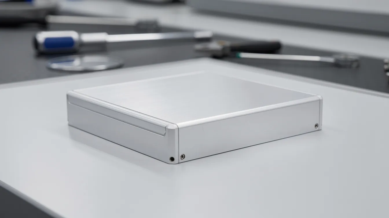
Case Snapshot: Cutting Flash and Finishing Time on an Aluminum Automotive Housing
An aluminum die casting housing (A380 alloy) for automotive electronics entered production with persistent flash problems. Flash up to 0.30–0.40 mm height appeared around the lid parting line and near two slider interfaces, requiring 40–60 seconds of manual grinding per piece. The casting surface on sealing areas showed flatness deviations, and rework rates ran at 4–5%.
Analysis revealed multiple contributing factors:
-
Machine clamp force met the theoretical requirement but lacked a safety margin once runners and overflows were included in the projected area calculation
-
Die temperature mapping showed 20–25°C variation across cooling circuits, causing uneven cooling and differential expansion
-
Shut-off lands on two inserts had worn rounded edges after ~45,000 shots
-
The pressure curve showed a high intensification spike indicating over-packing
Corrective actions included:
-
Spot-welded and polished shut-off lands to restore flatness within 0.02 mm
-
Tightened ejector pin bushings and realigned slide gibs
-
Moved the tool to a press providing 15% more clamping force margin
-
Lowered intensification pressure and smoothed the fill-to-pack transition to ensure proper flow without excessive pressure
-
Introduced a dedicated trim die for one-stroke flash and runner removal
Outcomes over the following six months:
-
Flash height reduced by 60–80% (from ~0.30 mm to 0.06–0.12 mm)
-
Manual finishing time cut in half-from ~50 seconds to ~25 seconds per part
-
Flash-related rejections dropped below 1%
-
Across an annual run of 100,000 parts, the labor and scrap savings offset the tool repair investment many times over
This case reinforces that flash elimination is a system problem requiring coordinated action across die design, machine capability, process parameters, and maintenance-not a single silver bullet.
Partnering with Anebon to Improve Die Casting Quality and Reduce Total Cost
Eliminating flash defects is not only about aesthetics. It directly impacts cost, cycle time, tool life, and reliability across the entire casting process. Every dollar saved in finishing is a dollar that drops straight to the bottom line, and every hour recovered from grinding is an hour available for production.
Anebon brings together the capabilities that matter for flash reduction: die design and DFM support, aluminum die casting with proper temperature control and process monitoring, high precision CNC machining for critical features, in-house trimming and finishing, and ISO-certified quality assurance systems. We support overseas OEMs in automotive electronics, robotics, medical equipment, and industrial machinery-sectors where tight tolerances, clean casting surfaces, and complex geometries are non-negotiable.
If you’re dealing with flash problems on existing tools or planning a new die casting program, send your 2D drawings and 3D models to Anebon’s engineering team for a manufacturability review focused specifically on reducing flash and finishing operations before tooling is cut. We’ll identify quick wins in your current setup and design improvements that deliver measurable cost reduction.
Request a quote or schedule a DFM consultation with Anebon today-and start turning flash waste into production savings.