Essential Tolerances in Machining: Achieving Precision in Production
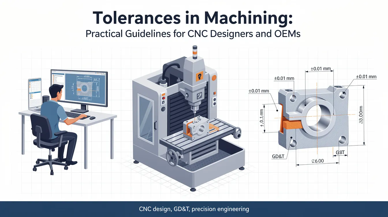
Tolerances in Machining: Practical Guidelines for CNC Designers and OEMs
Every cnc machining project begins with a simple question: how much variation can this part tolerate before it stops working? Machining tolerances define acceptable variation in part dimensions, and they directly determine whether components needed for an assembly will fit, function, and last. A tolerance dictates the allowable margin of error for a specific dimension-get it wrong, and you risk scrapped batches, failed assemblies, or worse.
What Is a Machining Tolerance?
Consider a 10.00 mm shaft designed for an automotive actuator. If the drawing specifies ±0.02 mm, the acceptable variation spans 9.98 mm to 10.02 mm. Anything within that window works; anything outside does not. This concept has roots stretching back to the second industrial revolution, when mass production demanded repeatable precision. The industrial revolution made component interchangeability possible-a gun barrel manufactured in one facility had to align with a firing pin made in another. Today, interchangeability allows parts manufactured in different batches to be swapped seamlessly in high volume production lines.
Tolerances directly influence production time, tooling requirements, and costs. Tighter tolerances improve product quality and reliability, but they also demand slower feeds, finer tools, and more rigorous inspection. Loose tolerances enable faster production and lower costs for manufacturers, which is why specifying only what your machining process truly requires is critical. Ignoring tolerances can lead to serious manufacturing mistakes across all manufacturing processes.
Where Anebon Fits
Anebon Metal Products Limited holds ISO 9001:2015 and ISO 14001:2015 certifications and offers standard machining tolerances of approximately ±0.10 mm for non-critical features. On request, our precision machining capabilities reach down to ±0.002 mm for critical bores, shafts, and mating interfaces. Industries where tight cnc machining tolerances matter most include medical device manufacturing, aerospace, robotics, and electronics-sectors where machining tolerances impact how components fit and function together. If your project demands exacting standards, send your drawings for a tolerance review.
Fundamentals: How Machining Tolerances Are Defined and Expressed
Before diving into tolerance types and strategies, let’s establish a few definitions that every design engineer should have at their fingertips.
Basic size vs. actual size. A drawing might specify a 25.00 mm bearing seat, but the finished part measures 24.98 mm. The basic size is the intended nominal; the actual size is what you measure. Dimensional tolerances define acceptable limits for linear or angular dimensions-expressed in metric values or imperial units-to control this gap. The allowable deviation between the two determines whether the part passes or fails.
Upper and lower limits. If a pin is specified between 9.95 mm and 10.05 mm, these are the upper and lower limits. The total tolerance band equals the upper limit minus the lower limit: 10.05 − 9.95 = 0.10 mm. This is a limit based tolerance approach, and it shows the maximum deviation permitted on that feature. Limit tolerances specify maximum and minimum acceptable dimensions directly, making them common on shop-floor drawings.
Bilateral and unilateral tolerances. Bilateral tolerances allow variation in both positive and negative directions from nominal. A bore specified as 10.00 ±0.05 mm means the acceptable range runs 9.95–10.05 mm. A unilateral tolerance restricts variation to one direction only: 10.00 +0.00/−0.10 mm means the part can be undersized but never oversized. In imperial, 1.000 +0.000/−0.005 in works the same way. ISO standards define hole/shaft deviations more rigorously than simple ± tolerances, so Anebon works from both imperial and metric drawings-but we recommend avoiding unnecessary decimal places unless specific dimensions functionally require them.
Types of Machining Tolerances Used in CNC Machining
Machining tolerances go beyond controlling size. Different tolerance types govern form, orientation, location, and profile-each serving a distinct role in ensuring cnc machined parts perform as designed. Dimensional tolerancing handles the basics, but complex assemblies demand more.
Size tolerances regulate linear and angular dimensions. A shaft might carry a unilateral tolerance (e.g., 10.00 +0.00/−0.02 mm) to prevent oversize interference. A drilled or reamed hole could use bilateral tolerances (e.g., 6.00 ±0.03 mm) to ensure adequate clearance. A slot width often uses limit tolerances (5.00–5.10 mm) for direct pass/fail checking.
Geometric dimensioning and tolerancing is a standardized system that controls the shape and location of features beyond what size tolerances can express. GD&T is governed by ASME Y14.5 standards and is widely adopted in global manufacturing practices. It controls the form, fit, and function of a part by specifying geometric characteristics like flatness and true position.
Key GD&T categories relevant to cnc machining include:
-
Form: defines acceptable straightness, flatness, circularity, and cylindricity. A horizontal machined surface on a mounting flange might require flatness within 0.02 mm. Profile tolerances relate to the curvature of a part’s cross-section, controlling curved surfaces and complex contours.
-
Orientation: orientation tolerances measure variations about a reference form. This includes parallelism between two parallel planes, perpendicularity of flat and perpendicular surfaces, and angularity. Perpendicularity determines whether a nearby vertical surface is square to its datum, and perpendicular part edges meet at true 90°.
-
Location: true position controls feature locations such as hole location relative to datum planes. This is among the more commonly used callouts for assembly-critical features.
-
Runout: runout tolerance measures fluctuation of a feature during rotation-critical for shafts and two concentric cylinders where concentricity matters. Imagine concentric cylinders inside a bearing housing: runout controls how much the inner surface wobbles relative to the outer axis.
Datum features and datum reference frames anchor these controls. A primary datum might be the main mounting surface, secondary a side face, tertiary an axis-forming the coordinate system against which all geometric tolerances are evaluated. Anebon follows ASME Y14.5 and ISO GPS equivalents and can help interpret GD&T on customer drawings.
Standard vs. Tight CNC Machining Tolerances
Understanding where standard tolerance ends and tight tolerance machining begins helps you make cost-effective decisions.
Standard tolerances in CNC machining are typically ±0.005″ to ±0.030″, or roughly ±0.10 mm to ±0.25 mm for non-critical features when the drawing is otherwise unspecified. The standard tolerance for CNC machining is typically ±0.010 inches or ±0.25 mm. Most milled surfaces and turned features fall comfortably within this range without special effort.
Tight tolerances are generally considered around ±0.005″ (≈ ±0.127 mm) for many shops, but in precision contexts, features at ±0.05 mm or below qualify. For critical dimensions like bearing seats and shafts, Anebon commonly achieves ±0.01–0.03 mm. Tolerances below ±0.001″ are very difficult to machine and typically require grinding, honing, or lapping. CNC machines can achieve tolerances as tight as ±0.0025mm, but only under ideal conditions with specialized equipment.
The cost implications are significant. Manufacturing time and costs increase when tolerances are tightened beyond standard levels. Applying tighter tolerances increases machining time and inspection frequency. Tighter tolerances require slowing down feed rates and specialized tooling, plus additional finishing passes and more frequent tool changes. Meanwhile, loose tolerances enable faster production and lower costs-so only tighten what your tolerance requirements actually demand.
A good rule of thumb: match decimal places to actual precision needs. Writing “10.000 mm” signals ±0.01 mm intent. Don’t add zeros unless the function requires them.
Surface Roughness and Its Relationship to Machining Tolerances
Surface roughness considerations go hand-in-hand with dimensional control. Surface finish tolerances specify allowable roughness on the machined surface, typically measured as Ra (arithmetic average roughness). A perfectly sized part with an unacceptably rough milled surface can still fail in service.
Anebon provides Ra ≈ 3.2 µm as the standard finish on most milled surfaces and turned features. Functional surfaces-bearing seats, seals, sliding interfaces-typically call for Ra 1.6 µm or Ra 0.8 µm. For a deeper dive, see our guide on how to accurately select surface roughness for CNC parts.
Specifying very smooth surfaces (Ra ≤ 0.8 µm) often requires additional considerations: grinding, polishing, or honing steps that add time and cost. Improving from Ra 3.2 to Ra 0.4 µm can triple finishing time. Surface roughness affects effective fit-in press fits, rough peaks can damage mating components; in sealing surfaces, valleys create leak paths.
Cosmetic surfaces also warrant attention. Secondary processes such as bead blasting, anodizing, or plating may slightly alter dimensions. Coating thickness must be accounted for in part tolerances to avoid pushing features out of spec after treatment.
Geometric Dimensioning and Tolerancing (GD&T) for Precision Machining
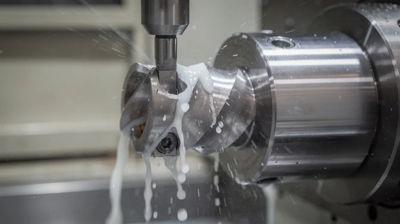
Geometric dimensioning and tolerancing is more than drawing decoration-it’s a language that defines how parts should fit and function, not just their nominal size. GD&T is a system for detailing machining tolerances that improves quality control by defining feature relationships. It is widely adopted in global manufacturing practices for good reason: it prevents over-specification while ensuring critical interfaces perform.
Key GD&T symbols in cnc machining include parallelism (controlling two parallel planes on a part), perpendicularity (ensuring perpendicular surfaces meet at true 90°), concentricity and runout (for rotating parts), true position (locating a machined hole relative to datums), and profile of a surface (controlling complex contours). Flatness tolerance controls how much a surface deviates from a perfect plane-critical for mounting interfaces. Maximum material condition modifiers allow additional positional tolerance when a feature is at its largest (for holes) or smallest (for pins), optimizing yield without sacrificing function.
Bracket example in practice. Consider a 6.00 mm dowel pin hole on an assembly bracket. The hole location must align with an automated fixture. Using a true position tolerance of ±0.05 mm (diametral tolerance zone of 0.10 mm) relative to Datum A (mounting face) and Datum B (side edge), you ensure repeatable alignment without over-constraining non-critical features on the same part.
GD&T reduces over-specification by concentrating precise tolerances on datums and functional interfaces while keeping secondary geometry under general tolerances. At Anebon, GD&T features are verified using CMMs and optical measurement systems. Complex GD&T callouts may require manual review rather than automated quoting-share your drawings and our engineers will provide DFM feedback.
Factors That Influence Achievable Machining Tolerances
Real-world part tolerances depend on intertwined factors that go well beyond the number on a machine spec sheet.
Material effects. Harder materials are better suited for tight-tolerance parts due to stability during machining-aluminum 6061-T6 machines easily but can deflect under clamping forces; stainless steel 316L work-hardens and generates heat; titanium alloys have low thermal conductivity, increasing thermal expansion risk. Softer materials are difficult to hold to very tight tolerances due to deflection during cutting. Engineering plastics like PEEK and Delrin introduce internal material stress that can cause post-machining warping. Precision in tolerances is vital to prevent machinery from overheating or failing when thermal effects go unmanaged.
Part geometry. Thin walls vibrate, long slender shafts deflect, and deep pockets trap heat-all degrading dimensional accuracy. Tight tolerances leave little room for error due to tool wear or thermal expansion, and complex geometries amplify these challenges.
Machine and tooling capability. Achieving sub-millimeter tolerances requires high-end CNC machines and precise cutting tools. 5-axis machining centers with low spindle runout, advanced feedback systems, and temperature-controlled environments are essential for ultra-tight work. Shrink-fit toolholders, precision vices, custom fixtures, and in-process probing all improve repeatability.
Process control. Coolant management, thermal stabilization, and consistent cutting parameters ensure that part-to-part variation stays within spec across production runs. Anebon evaluates all these factors during our DFM review of customer drawings.
Inspection, Quality Control, and Metrology for Tight Tolerances
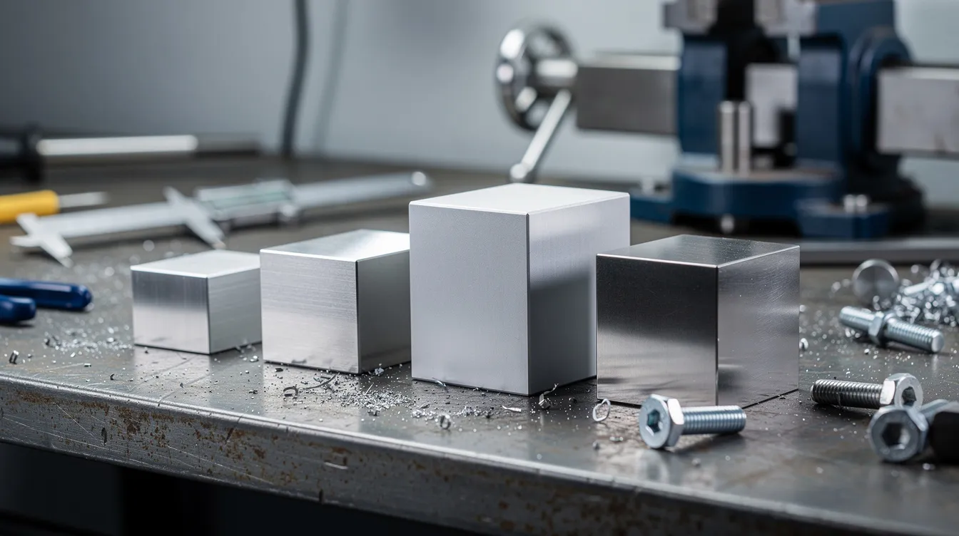
Holding tight cnc machining tolerances is meaningless without reliable measurement. Tighter tolerances require more rigorous inspection methods and equipment, and the instruments must match the precision demanded.
Manufacturers often use advanced methods like CMMs for inspection under tight tolerances, supplemented by optical projectors, surface roughness testers, micrometers, and gauge blocks. The “10:1 rule” guides instrument selection: verifying ±0.01 mm tolerance requires measurement resolution of at least 0.001 mm. Without this ratio, measurement uncertainty masks true part variation.
Anebon’s ISO 9001:2015 quality control framework covers the full chain: incoming material verification, first-article inspection (FAI), in-process checks, and final dimensional reports. For critical aerospace and medical device manufacturing parts, we provide full inspection documentation with traceability. ISO 2768 specifies general tolerances for manufacturing parts, and Anebon applies these as defaults where drawings don’t specify tighter control. For general industrial components, simplified checks with consistent inspection protocols maintain cost efficiency without compromising reliability.
Industry Examples: Where Tight Machining Tolerances Are Essential
Not every part needs micron-level control, but several sectors absolutely depend on it. Aerospace, medical, and automotive parts require much tighter tolerances than standard.
Medical devices. Components like orthopedic implants, surgical instruments, and diagnostic equipment housings typically demand ±0.01–0.02 mm tolerances with surface finishes of Ra ≤ 0.8 µm. Imprecise tolerances in medical devices can compromise patient safety-there is no margin for “close enough” on an implant interface.
Aerospace and defense. Tight tolerances are essential for critical applications like aerospace. Turbine components, actuator housings, and structural brackets need tight concentricity, flatness, and true position control. Rivet holes in aircraft require extremely tight tolerances for safety; even small positional errors across hundreds of holes create dangerous cumulative stress. These are aerospace components where failure is not an option.
Electronics and semiconductor. As devices shrink, heat sinks, RF shields, and micro enclosures for electronics applications demand precise geometry, tight hole location, and controlled finishes for thermal contact and electromagnetic sealing.
Industrial automation and robotics. Precision gears, linear motion guides, and sensor housings depend on stacking tolerances remaining controlled-errors compound across multi-part assemblies, degrading system accuracy quickly.
Anebon’s cnc machining, die casting, and sheet metal capabilities support all these sectors from prototype through production with appropriate tolerance control.
Design Guidelines for Specifying Practical CNC Machining Tolerances
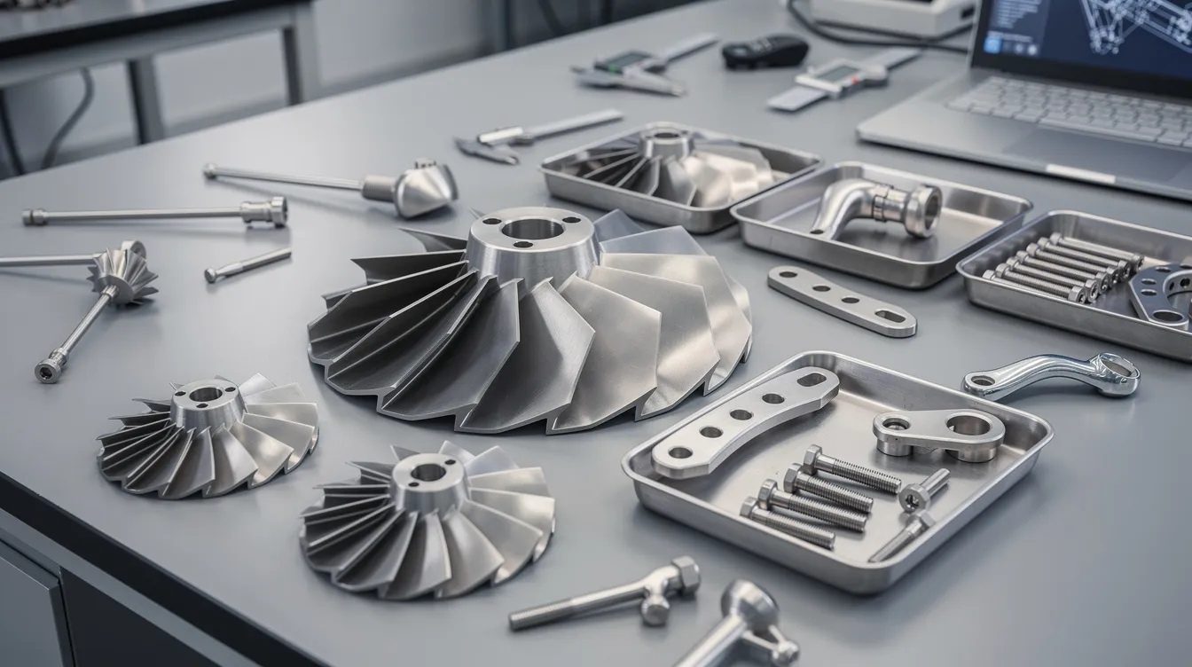
This section is for design engineers sitting in front of a CAD model wondering how tight to go. Here are tolerancing guidelines that save money without sacrificing function.
Specify the loosest tolerance that works. Every dimension should pass a simple test: what fails if this feature drifts beyond this tolerance? If the answer is “nothing functional,” loosen it. An overly stringent tolerance on a non-critical face does nothing but increase machining time, unnecessarily increasing costs.
Understand fit types. Clearance fit allows free movement between two parts-common for sliding covers. Transition fit involves parts that fit snugly and require assembly-typical for locating pins. Interference fit requires force to assemble two overlapping parts together-used for permanent press-fit bushings. Match your fit type to your functional need, and use standardized tolerances like H7/h6 for shafts rather than arbitrary values.
Manage tolerance stack-up. Tolerance stack-up can prevent parts from mating properly if not managed. Across a multi-feature assembly, cumulative errors from tolerance stack-up can cause misaligned parts in assemblies. Use GD&T datum-based control to anchor critical feature locations and let non-mating cosmetic surfaces float under general tolerances. Tolerances control functionality between mating parts in assemblies, and fit tolerances dictate how two mating parts interact with each other.
Use ISO 2768 wisely. Apply ISO 2768-m (medium) as your drawing default for general features. Override only on critical features with precise tolerances. This keeps drawings clean, reduces quoting confusion, and prevents shops from guessing your intent on non-critical areas.
Encourage early collaboration. Complex GD&T, ultra-tight tolerances (< ±0.01 mm), or unusual materials benefit from DFM review before drawings are finalized.
Working with Anebon Metal Products Limited on Tight-Tolerance Projects
Anebon Metal Products Limited brings over fifteen years of experience in precision cnc machining, die casting, and sheet metal fabrication. Our tolerance capabilities extend down to ±0.002 mm for critical features, supported by 5-axis machining centers, multi-axis turning, in-process probing, and dedicated inspection labs with CMM verification.
Our typical engagement follows a straightforward path: submit your RFQ with 2D drawings and 3D models, receive a DFM and tolerance review with suggested adjustments, approve a quotation that reflects realistic machining and inspection scope, and move through sample approval into production. We serve overseas OEMs across automotive, aerospace, electronics, industrial machinery, and medical device manufacturing with consistent tolerance control and full traceability.
With ISO 9001:2015 and ISO 14001:2015 certifications, Anebon delivers robust quality control and environmental management for high-spec projects. Whether you need a handful of prototypes or thousands of production parts, tolerances ensure interchangeability in mass production-and we build that reliability into every order.
Ready to get your tolerances right? Upload your drawings and tolerance requirements today for a detailed review and quotation from our engineering team.