Essential Strategies for Preventing Deformation in Custom Sheet Metal Production
When warping, twisting, or dimensional drift creep into custom sheet metal parts, the consequences cascade quickly: assemblies don’t fit, cosmetic surfaces ripple, and production schedules slip. For OEM programs shipping overseas, even a fraction of a millimeter matters. Preventing deformation in custom sheet metal production requires effective design and material management strategies applied at every stage of the fabrication process.
At Anebon Metal Products Limited, we work with design engineers and purchasing teams worldwide to deliver precision sheet metal fabrication with tolerances as tight as ±0.002 mm on critical cnc machining features. Preventing deformation in custom sheet metal manufacturing relies on controlling heat and managing stress from the first CAD sketch through final inspection.
In sheet metal, “deformation” covers several distinct failure modes: springback (elastic recovery after bending), local buckling and wrinkling at flanges, warping and distortion after cutting or welding, and hole ovalization near bend lines. This article walks through the full production process-design phase, laser cutting, sheet metal bending, welding, and quality control-with concrete strategies to avoid deformation at each step.
Start in the Design Phase: Build Deformation Prevention into the Model
Most deformation issues are locked in during the design phase, long before any press brake or laser cutting program runs. Poor sheet metal design choices compound through every downstream operation. Stress management is critical to minimizing deformation near weak points in sheet metal, and it starts here.
We recommend that overseas OEMs initiate an early DFM review with Anebon’s engineers while CAD models are still flexible-ideally before design freeze milestones such as EVT. This is the cheapest point to catch problems and the most impactful stage for a successful sheet metal design.
Key design principles to follow:
-
Use standard sheet gauges and maintain uniform wall thickness across the part geometry. Variations in sheet metal thickness create uneven stress distribution during forming and welding.
-
Material selection impacts ease of forming and springback behavior in sheet metal fabrication. Choosing softer tempers, appropriate alloys, and understanding grain direction relative to bend axis orientation prevents unnecessary rework.
-
Optimizing part design with bends instead of large flat surfaces increases rigidity in sheet metal. Formed ribs, flanges, and stiffening features resist oil-canning and improve the final product’s structural performance.
-
Using interlocking tabs and slots in designs can reduce distortion in assembled metal parts by distributing loads and improving joint alignment before welding.
-
Material expansion must be accounted for in design, particularly for assemblies that see thermal cycling in service or during welding.
Common sheet metal design mistakes that increase deformation risk:
-
Placing holes or slots too close to bend lines
-
Specifying flanges shorter than the minimum flange length the tooling can support
-
Using inconsistent bend radii or mixing bend orientations without purpose
-
Failing to define accurate k factor values early, leading to cumulative flat pattern drift
-
Ignoring grain direction in the sheet, which can change the minimum bend radius requirement by 10–20%
A design engineer who used a generic CAD default k factor of 0.50 while the fabricator’s empirical value was closer to 0.42 ended up with flat pattern lengths off by 0.5–1 mm on long bends in 2–3 mm thick steel. That mismatch forced rework or re-bending across an entire batch.
The design process is where you set the foundation for designing sheet metal parts that survive every subsequent operation without deformation.
Control Bend Geometry: Correct Bend Radius, K-Factor, and Flange Lengths
Getting bend geometry right is the single most impactful technical decision in the bending process. Three parameters control most outcomes: bend radius, k factor, and flange length.
Bend Radius
The inside bend radius should equal at least the material thickness. For ductile materials like mild steel and soft aluminum, a correct bend radius of R ≥ 1 × T (where T is sheet thickness) is the practical minimum. For stainless steel and high-strength alloys, the bend radius should be 1–1.5 times material thickness, and often 2× T for thicker gauges.
Optimizing bend radius can prevent cracking and excessive springback in sheet metal. A smaller bend radius than recommended causes outer fiber cracking (material cracking on the tension side) and wrinkling on the inner radius, especially in stainless steel. Stainless steel may require precise tooling to avoid cracking due to its work-hardening behavior. Meanwhile, aluminum has good formability and minimal springback, making it more forgiving with tighter radii.
Maintaining proper bend radii prevents fracturing or distortion in sheet metal parts. Material thickness should be at least 1–1.5 times the bend radius to keep the geometry stable.
Avoiding sharp internal corners with small radii reduces stress concentrations in sheet metal. When you need complex shapes, use radii that respect the material type and sheet thickness.
K-Factor and Bend Allowance
The k factor defines where the neutral axis sits within the material during bending-expressed as the ratio of the distance from the inside surface to the neutral axis divided by total material thickness. The K-factor ranges from 0.25 to 0.50 for material bending, with typical values around 0.42 for most steels and aluminum alloys, and understanding these fundamentals is essential for safe, precise sheet metal bending operations.
An accurate k factor, calibrated against Anebon’s real forming data for each material-tooling combination, directly improves flat pattern accuracy and reduces trial-and-error on the shop floor. The bend allowance formula uses this value:
Bend Allowance = (π/180) × bend angle × (inner radius + K × thickness)
When the k factor is wrong, the flat pattern stretches or shrinks, and flange lengths shift. This forces re-bending, which introduces additional deformation and cumulative dimensional error. Springback compensation is essential in sheet metal design. The springback factor, KS, defines the final bend angle ratio and depends on material properties. Springback compensation calculations depend on yield strength-choosing metals with higher yield strengths can prevent spring-back in sheet metal fabrication, though it increases forming force requirements.
Key springback control methods:
-
Overbending compensates for springback in sheet metal bending by forming slightly beyond the target bend angle
-
Using coining reduces potential for springback in elastic materials by applying compressive force after forming
-
Bend angles typically have a tolerance of +/- 1 degree, which is a standard a +/- 1 degree tolerance on all bend angles
Flange Length
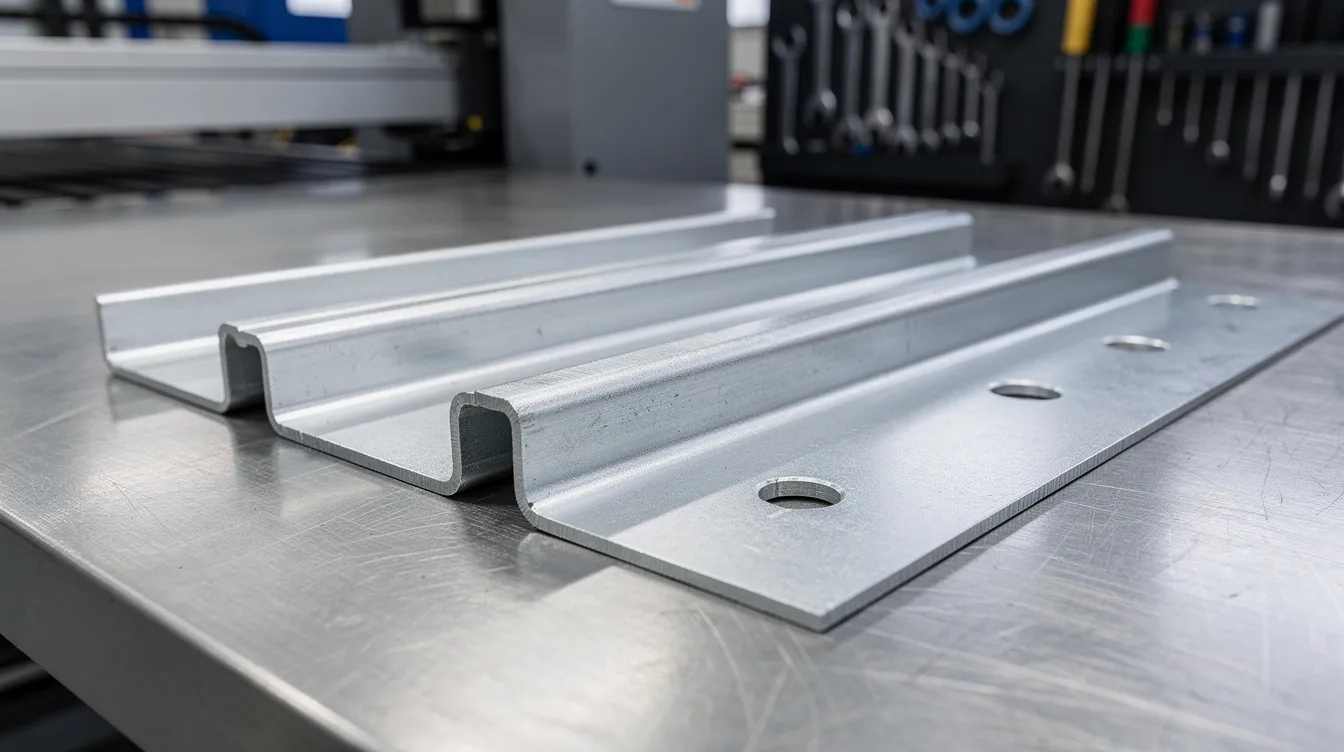
Flange length must be at least 4 times the material thickness to ensure the bent flange is fully supported by tooling without slipping or twisting. For example, a 2 mm thick mild steel part needs a minimum flange length of at least 8 mm, which is comparable to common sheet metal gauges used in automotive body structures. For bottom bending or shallow die openings, 6× T may be required.
A bent flange shorter than this threshold will twist, produce non-parallel edges, and resist consistent forming. When designing sheet metal parts, use consistent bend radius and orientation across the design wherever possible-this reduces re-clamping, lowers variation, and minimizes risk of twist in the final product. Following standard angles and keeping bends in the same direction also streamlines the bending process.
Use Bend Relief and Feature Spacing to Avoid Local Tearing and Buckling
Bend relief cuts are small notches placed at the junction of a bend line and an edge or adjacent feature. Without them, the material stretches, tears, or “pulls” at corners during forming-destroying the desired shape and creating stress risers, which is especially critical when laying out and forming conical sheet metal components from flat patterns.
Sizing Bend Reliefs
A properly sized bend relief prevents tearing, edge distortion, and corner pulling when flanges are formed. Guidelines:
-
Relief width (perpendicular to the bend line) should be at least equal to material thickness
-
Relief depth (along the bend line) should be at least equal to the bend radius plus material thickness
-
For a 2 mm thick mild steel part with a 2 mm inner radius: relief width ≥ 2 mm, depth ≥ 4 mm
-
Common relief shapes include teardrop, rectangular, and rounded profiles-each suited to different geometries
For hems, the minimum inside diameter equals the material thickness, especially in open and closed hems where safe edge formation depends on that relationship, similar to best practices for rolling and forming the edges of sheet metal.
Smart bend relief design dramatically reduces rework, especially in boxes, brackets, and enclosures with multiple corners where several bends converge, and is particularly important when bending sheet metal into circular or cylindrical forms.
Feature Spacing from Bend Lines
Holes should be at least three times the material thickness away from bends to prevent stretching. More precisely, holes should be at least 2.5 times material thickness from bends as a general rule, and the minimum distance required is often calculated as bend radius + material thickness for the tightest allowable placement.
Additional spacing rules:
-
Holes should be located at least two times the material thickness from any edge to avoid distortion
-
Holes should be at least equal to the material thickness in diameter to maintain punch integrity
-
Slots and elongated features need even more clearance-typically 3–4 times the material thickness from bend lines
-
Conical holes and extruded features near bends require careful evaluation, as their geometry amplifies local stress
When spacing is insufficient, holes ovalize into teardrop shapes, flanges warp locally, and the dimensional accuracy of precision sheet metal components degrades. In a sheet metal project with multiple closely spaced features, even 0.5 mm of feature migration can cause assembly failure.
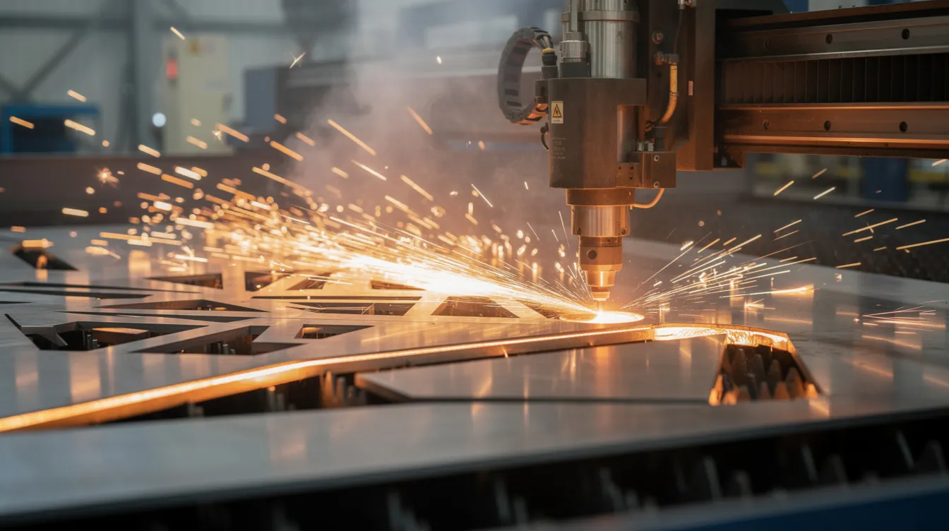
Optimize Cutting: Laser Cutting Parameters and Kerf Management
Laser cutting is often the first physical operation performed on flat sheets, and how much material is affected by heat at this stage carries forward through every subsequent step.
Uneven or excessive heat input during laser cutting introduces residual stresses and edge hardening in the heat affected zone. These residual stresses later amplify bending deformation, cause unexpected springback variation, and can lead to material distortion during welding. Surface roughness tolerance is +/- 3.2 micrometers for cut edges that feed into precision forming.
Anebon uses modern fiber laser cutting with optimized parameters-power, speed, and assist gas type-to maintain a narrow kerf and minimize heat-affected zones. Critical dimensions must adhere to machinery guidelines for accuracy, particularly when cut edges become datum references for subsequent forming, and can be further refined with high-precision aluminum CNC machining capabilities.
Fiber Laser vs CO₂ Laser: Deformation Impact
|
Parameter |
Fiber Laser |
CO₂ Laser |
|---|---|---|
|
Kerf width |
Narrower (typically 0.1–0.15 mm) |
Wider (0.15–0.3 mm) |
|
Heat input |
Lower |
Higher |
|
Heat affected zone depth |
Shallower |
Deeper |
|
Cut edge quality |
Finer, less bevel |
More bevel, possible discoloration |
|
Residual stress in blank |
Lower |
Higher |
|
Best suited for |
Thin to medium sheet, high precision |
Thicker materials, some non-metals |
Nesting and Kerf Compensation
-
Maintain 1–2 mm spacing between parts and 2–5 mm from the sheet edge to reduce distortion from cross-over cuts
-
Correct kerf compensation in computer aided manufacturing programming preserves critical dimensions on the flat pattern before forming, avoiding extra machining or rework
-
For extremely tight tolerances or thicker materials, combining laser cutting with secondary cnc machining on key interfaces helps maintain high precision while the bulk of the blank is cut thermally
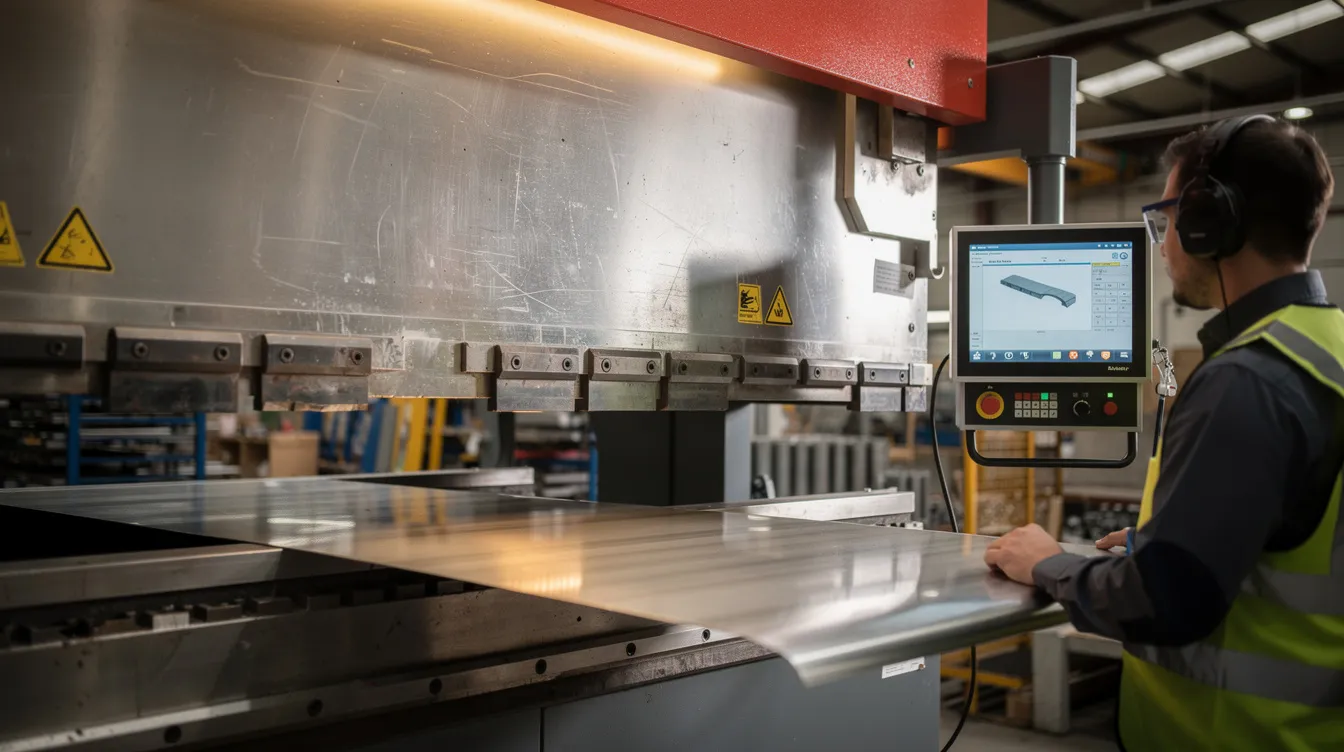
Precision Forming Techniques: Press Brake Setup, Sequencing, and High Precision Tooling
The forming stage is where flat sheets become three-dimensional sheet metal parts, and where the cumulative effect of every upstream decision becomes visible. High-quality tooling reduces friction and evenly distributes forces in sheet metal forming, directly supporting the correct bend radius and minimizing cracking or wrinkling.
Tooling Selection
-
V-die opening width should generally be 8–12× material thickness for mild steel and carbon steel. Narrower openings increase bending force and risk compressing the material inaccurately.
-
Punch radius should match or slightly exceed the target inside bend radius.
-
Die surface finish matters-smooth surfaces reduce scratch marks and stress concentrations on curved surfaces.
Bend Sequencing
An efficient bend sequence distributes stresses evenly during sheet metal fabrication. Bending sequence impacts final shape and part integrity, so planning is not optional-it’s a critical process.
Recommended sequencing logic:
-
Bending sequence should follow least to most complex order
-
Form internal features first, then outer flanges
-
Bending from outside in helps prevent distortion when part geometry requires it
-
Keep bends in the same direction where possible to reduce part flipping
-
Optimizing bend order reduces collision risks during production
-
Using 3D simulation software aids in determining bend sequence before committing to the shop floor
Improper bend sequencing is one of the most common causes of cumulative twist in complex geometries. Parts that look fine after the first two bends can develop 2–3 mm of twist by the fifth.
Springback and Support
Anebon’s CNC press brake equipment features programmable backgauges and angle measurement systems to achieve accurate bends and compensate for springback in real time. Computer numerical control systems allow repeatable, data-driven forming across production runs.
Using proper supports during forming can minimize deformation in sheet metal fabrication. For large panels, die crowning, support arms, and custom fixtures prevent sagging and oil-canning. Keeping a consistent bend direction across the part reduces handling-induced deformation and keeps the manufactured object within tolerance through the entire production process.
Managing Welding and Post-Processing Stress to Avoid Warping
Welding thin sheet metals-particularly 304 or 316L stainless steel-introduces significant localized heat and residual stress. For materials under 3 mm, this is often the single largest source of warping in the manufacturing process. Minimizing heat input during welding helps prevent deformation in sheet metal, and following best practices for welding thin sheet metal panels is essential to keep distortion under control.
Welding Strategies to Control Distortion
-
Use staggered or stitch welds instead of continuous beads. In one project involving a 1.5 mm 304 SS enclosure, switching from continuous fillet welds to stitch welds with formed ribs and balanced weld layouts reduced twist from approximately 5 mm to 0.8 mm-a dramatic improvement in the final product.
-
Use shorter bead lengths (20–50 mm segments with gaps 2–3× the bead length) to reduce heat buildup
-
Balance welds symmetrically across the assembly so contraction forces cancel rather than accumulate
-
Plan weld sequencing using back-stepping (center outward) to prevent shrinkage pulling the part into a curved shape along a straight line
Advanced Processes
For high-end applications requiring minimal distortion, consider:
-
Pulsed TIG welding with controlled heat input
-
Laser welding for narrow, deep penetration with minimal heat affected zone
-
Resistance welding for overlapping thin sheets in the same plane
These approaches align with advanced techniques for welding very thin sheet metal effectively.
Anebon designs and fabricates custom fixtures to hold complex assemblies during welding, controlling dimensional change for aerospace and semiconductor customers. Proper fixturing can reduce geometric variation by 10–40% compared to unconstrained welding.
Post-Weld Stress Relief
Post-fabrication stress-relief heat treatments can reduce residual stresses in precision metal parts. For critical components, mechanical straightening and localized heat treatment should be planned into the manufacturing process rather than treated as afterthoughts, drawing on proven methods for flattening and correcting deformed sheet metal. Choosing metals with higher yield strengths can prevent spring-back during both forming and post-weld handling of thicker materials.
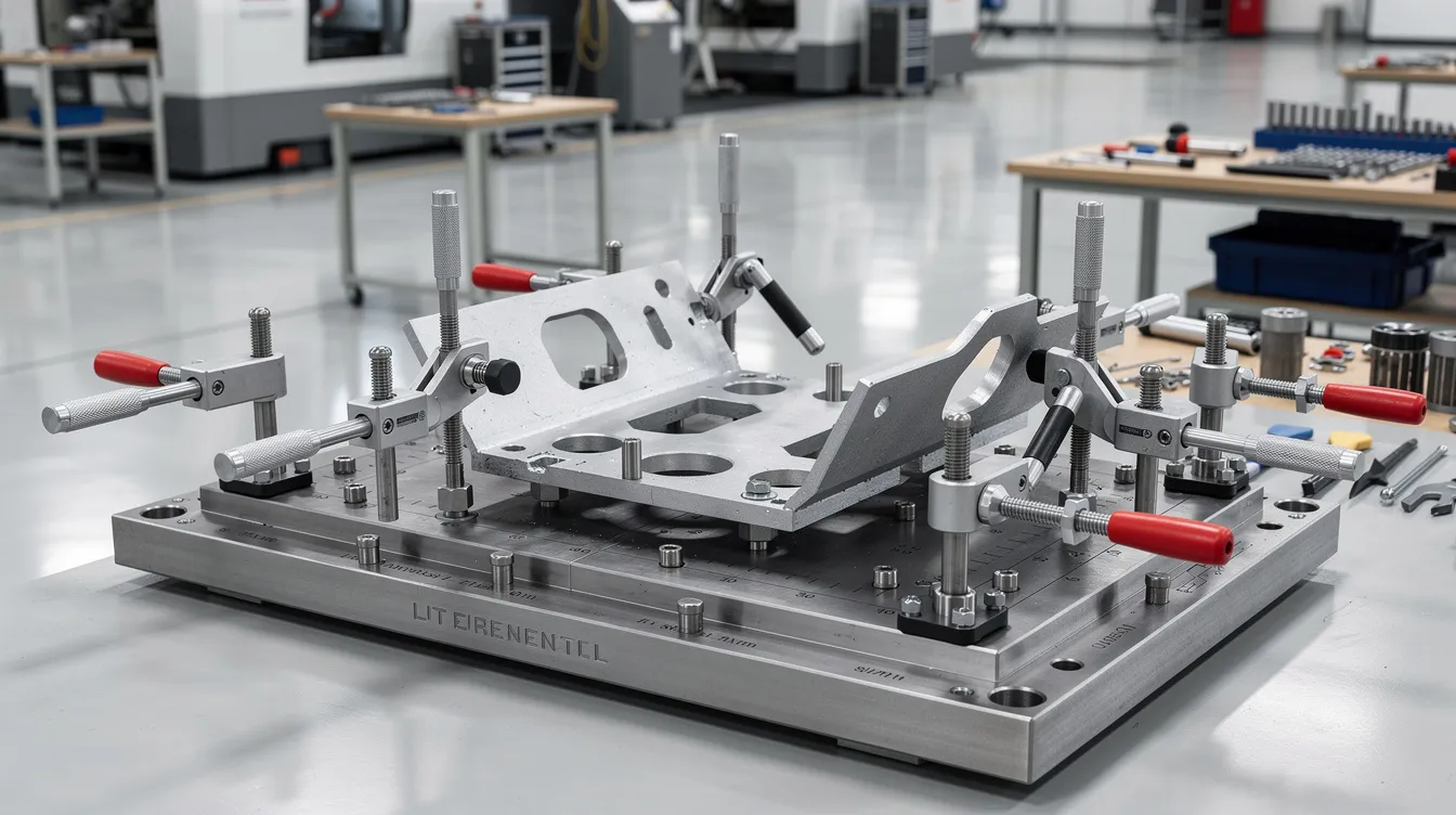
Integrating CNC Machining with Sheet Metal for Critical Interfaces
Not every feature on a sheet metal part can be held to extreme tolerances through forming alone. Hybrid processes-sheet metal fabrication plus cnc machining-provide the path to high precision where deformation tolerance is extremely tight.
When to Machine After Forming
Recommend designing sheet metal parts so that critical datums and mating faces can be finish-machined after forming, correcting any minor deformation from bending or welding. This approach is particularly valuable in custom manufacturing for aerospace, medical devices, and robotics.
Typical features Anebon machines post-forming:
-
Locating holes and precision slots held to ±0.02 mm or better
-
Mounting bosses and countersinks requiring exact depth and position
-
Sealing grooves and datum surfaces that must lie in the same plane across large assemblies
-
Edge profiles where the arc length or flatness must meet functional requirements beyond what laser cutting or forming alone can deliver
Datum Coordination
Coordinate datum definitions between the sheet metal fabrication drawings and machining drawings. When both operations reference the same physical datum features, inspection results align and assembly errors drop. This is especially important when the manufactured object passes between sheet metal and machining departments-or between Anebon and the customer’s assembly plant overseas.
Combining laser cutting with CNC milling at critical edges also enhances cosmetic appearance, removes heat-affected material, and improves corrosion resistance on sealing surfaces for the final product.
Quality Control, Measurement, and Feedback Loops
Deformation prevention is reinforced by strong inspection-catching twist, bow, and out-of-flat conditions before the part reaches final assembly. Consistent quality starts with the right tools and processes.
Inspection Tools
-
Coordinate Measuring Machines (CMM) for dimensional accuracy on complex geometries
-
Laser trackers for large assemblies
-
Dedicated go/no-go gauges for rapid inline checks
-
Surface plate flatness verification
-
Angle gauges for verifying bend angle within the standard +/- 1 degree tolerance
-
Profilometers for measuring curvature, warpage, and surface profile
In-Process Checks
Rather than relying solely on final inspection, Anebon implements checks at key stages:
-
After laser cutting: verify part flatness, edge quality, and residual distortion on the flat pattern
-
After first-off bending: measure angles, flange length, and feature positions against the model
-
After welding: inspect assembly distortion before releasing from the fixture
This approach catches problems early, when correction is cheapest and least likely to introduce additional material distortion.
Continuous Improvement
Measurement data feeds back into updated bend allowance tables, k factor values, and forming parameters for future batches. Over production runs, this data-driven loop tightens the gap between predicted and actual material behavior, supporting consistent quality across volumes.
ISO 9001:2015 certification ensures quality management standards that underpin traceable, repeatable control over deformation throughout the production process. Anebon also holds ISO 14001:2015 certification, supporting environmental controls (temperature, humidity) that influence material properties and forming behavior across seasons and production environments.
Practical Design Checklist to Avoid Deformation in Your Next Sheet Metal Project
Use this checklist when preparing your next sheet metal project for fabrication:
-
Verify material type, material thickness, and temper for the application; confirm how much material is needed and whether softer materials or thicker materials better suit the geometry
-
Confirm correct bend radius (≥ 1× T for mild steel and aluminum; ≥ 1.5–2× T for stainless steel and high-strength alloys)
-
Set the k factor based on real forming data, not CAD defaults (range: 0.25–0.50)
-
Ensure minimum flange length ≥ 4 times the material thickness
-
Add bend relief at every bend-to-edge or bend-to-bend intersection; size relief to at least R + T in depth
-
Maintain safe distance between bend lines and holes (≥ 2.5–3× T), edges (≥ 2× T), and slots (≥ 3–4× T)
-
Align bends in a consistent direction where possible; follow standard angles to minimize tooling changes
-
Account for grain direction relative to the bend axis
-
Choose appropriate laser cutting strategies to minimize heat affected zone on the flat pattern
-
Plan welding sequences and specify stitch vs continuous welds based on distortion sensitivity
-
Identify features requiring CNC machining post-forming for tight tolerances and complex shapes
-
Specify flatness and positional tolerances on drawings (e.g., < 0.5 mm over 300 × 300 mm for cosmetic panels)
-
Account for material expansion in assemblies subjected to thermal cycling
-
Use latest fabrication techniques and rapid prototyping to validate complex geometries before committing to production tooling
Send your STEP or DXF files to Anebon for a free DFM review and deformation risk assessment before locking final drawings. Our engineers can evaluate your bend radius, flange length, feature spacing, and overall manufacturability against real production data.
Conclusion: Designing for Stability and High Precision with Anebon
Preventing deformation in custom sheet metal production is not a single technique-it’s a unified strategy spanning the design process, fabrication process control, and inspection. Every decision from material selection to bend sequencing to weld layout either compounds or reduces deformation risk. The most cost effective approach is always prevention for OEMs focused on cost effectiveness: fixing a flat pattern in CAD costs minutes, while reworking a bent part on the shop floor costs hours and scrap.
Anebon Metal Products Limited brings together precision sheet metal fabrication, cnc machining, die casting, and rapid prototyping under one roof, serving industries including aerospace, medical devices, automotive, electronics, and robotics. Our ISO-certified processes, empirical forming databases, advanced technology, and engineering review capabilities, backed by expert support, help overseas OEM customers improve value and maintain cost effectiveness as they scale from prototype to mass production-ensuring every manufactured object meets specification from prototype through full-scale production.
Ready to eliminate deformation risk from your next project? Contact Anebon’s engineering team with your 3D models and drawings. We’ll review your bend radius, flange lengths, feature spacing, and overall manufacturability-then deliver a detailed DFM report and competitive quote to get your parts into production with confidence.