Essential Guide to Welding Sheet Metal: Techniques and Tips
Welding Sheet Metal: Methods, Techniques, and OEM-Grade Best Practices
Introduction to Welding Sheet Metal
Welding sheet metal-typically defined as metal sheets ranging from 0.4 mm to 6.0 mm thick-is one of the most demanding tasks in metal fabrication. Unlike welding steel plate, thin sheet metal expands and warps quickly under intense heat, making heat control the single most important variable in every welding project. Effective welding of sheet metal requires managing heat to prevent burn-through and warping, while simultaneously achieving a strong, clean weld that meets dimensional and cosmetic standards.
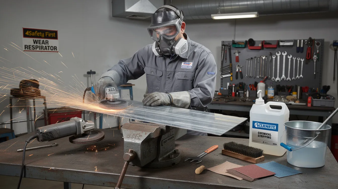
The most common methods used to weld sheet metal today include mig welding (gas metal arc welding / GMAW), tig welding (gas tungsten arc welding / GTAW), resistance spot welding, plasma arc welding, and laser welding. Anebon Metal Products Limited specializes in precision sheet metal fabrication for OEMs across automotive, electronics, medical, and robotics industries, routinely welding mild steel, stainless steel, and aluminum alloys to tight tolerances. In our experience, tig welding and gas metal arc welding are preferred when controlling distortion and appearance on thin sheet metal, while laser and spot welding serve high-volume production lines. Welding exposes you to several hazards requiring protective measures, so all work should be performed in well-ventilated areas, and operators must wear appropriate personal protective equipment to prevent injuries.
Key challenges covered in this guide:
-
Managing material thickness variability (0.4–6.0 mm) and its impact on heat input
-
Minimizing the heat affected zone to prevent microstructural damage and discoloration
-
Controlling distortion across flat surface, horizontal, vertical, and overhead orientations
-
Achieving cosmetic weld bead quality for visible OEM parts
Core Welding Processes for Sheet Metal
Choosing the right welding process depends on material type, material thickness, and production volume. Welding machines require shielding gas to protect welds from atmospheric contamination in every arc welding process, and gas composition directly influences spatter, penetration, and weld appearance on thin materials.
Here is a summary of the major processes used in sheet metal welding:
-
MIG (GMAW): High deposition rate, best for mild steel and carbon steel ≥ 1.0 mm
-
TIG (GTAW): Precision arc welding process for thin sheets < 1.5 mm; superior cosmetic finish
-
Resistance spot/seam: Automated, high-speed joining for overlapping metal pieces in production
-
Plasma arc welding: Constricted arc for deeper, narrower welds on stainless 1–6 mm
-
Gas welding (oxy-acetylene): Legacy method, mostly repair or low-volume work
-
Laser / electron beam welding: Minimal heat affected zone, tight fit-up, high-precision applications
Anebon commonly uses MIG, TIG, and spot welding for OEM production, with laser welding coordinated for specialized assemblies.
MIG / Gas Metal Arc Welding (GMAW) for Sheet Metal
MIG welding uses a continuous solid wire electrode fed through a welding gun, creating an arc between the wire and workpiece. The weld pool is protected by shielding gas-typically a mixture of 75% argon and 25% carbon dioxide (C25) for mild steel. MIG welders use a continuously fed wire electrode, which makes the process fast, semi-automatic, and relatively easy to learn and efficient for general fabrication.
MIG welding is preferred for speed and efficiency on carbon steel, making it the go-to welding method for automotive bodywork, HVAC ducting, and structural brackets. MIG welding is faster than TIG welding and is preferred for thicker materials, generally best suited for sheet ≥ 1.0 mm. However, mig welding sheet metal thinner than ~0.8 mm carries higher risk of burn through, spatter, and warping compared to TIG.
For detailed setup guidance, see our guide on how to MIG weld sheet metal.
Recommended starting settings for mild steel (source):
|
Sheet Metal Thickness |
Wire Diameter |
Voltage |
Current |
|---|---|---|---|
|
0.8 mm (24 ga) |
0.6 mm (.023 in) |
14–15 V |
40–60 A |
|
1.2 mm (20 ga) |
0.8 mm (.030 in) |
16–17 V |
70–90 A |
|
1.6 mm (16 ga) |
0.8 mm (.030 in) |
17–18 V |
80–100 A |
TIG / Gas Tungsten Arc Welding (GTAW) for Sheet Metal
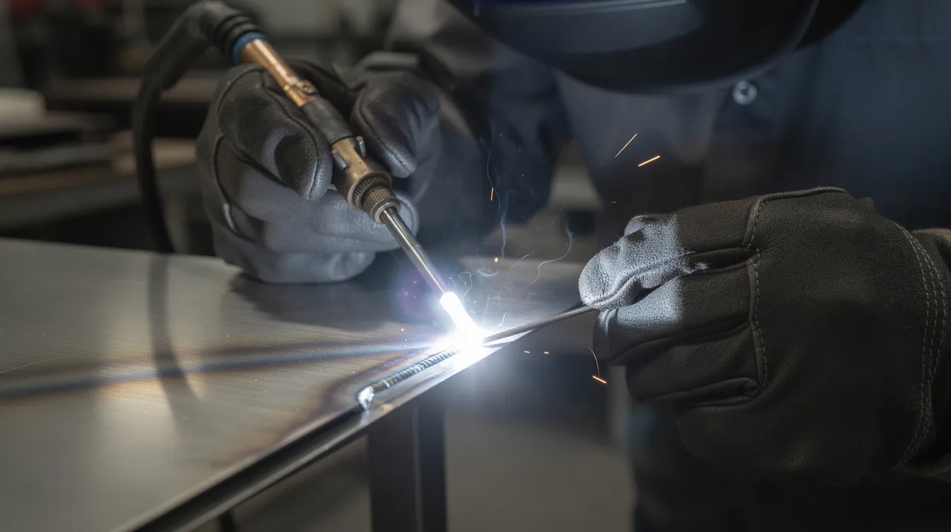
The tig welding process uses a non consumable tungsten electrode to generate the arc, with a separate filler rod added manually and an inert shielding gas-typically pure argon for steel and stainless steel. TIG welding produces the clearest, most precise welds with no slag, and offers superior aesthetics and cleaner results for thin sheet metal. TIG provides more precise control over the weld puddle, making it the best welding process for the thinnest sheet metal down to ~0.5 mm.
Unlike tig welding, MIG cannot match this level of cosmetic control, which is why TIG is better for thin work requiring precision and aesthetics-think medical housings, electronics enclosures, and aerospace brackets. TIG welding offers high precision for stainless steel applications and is ideal for thin materials and cosmetic applications.
Practical tips:
-
Use 1.0–1.6 mm ceriated or lanthanated tungsten electrode, sharpened to a fine point
-
Set DC electrode negative (DCEN) for steel; AC mode for aluminum
-
Use pulsed TIG on thin-gauge stainless and thin aluminum to narrow the heat affected zone
-
Keep torch angle at 10–15°, arc length short, and filler rod diameter equal to or slightly less than base metal thickness
-
Maintain high argon purity via gas lens; gas flow 6–9 LPM
For more on this specific welding process, see how to weld thin sheet metal.
Resistance Spot and Seam Welding in Sheet Metal Fabrication
Spot welding uses copper electrodes to join sheet metal by compressing metals between electrodes to melt and fuse them through resistance heating. Spot welding creates a permanent structural connection, making it ideal for overlapping thin sheets in automotive body-in-white and appliance production.
Typical thickness ranges span 0.5–3.0 mm combined stack-up per spot. Seam welding is a variation where rotating electrode wheels produce continuous welds or intermittent welds along a joint for leak-tight seams on tanks or enclosures. For a deeper comparison, see our article on spot welding vs riveting for high-load enclosures.
-
Cycle times of 10–100 milliseconds per spot enable high-volume OEM throughput
-
Spot welding is permanent and automation-friendly; tack welds are temporary pre-positioning steps for MIG/TIG seams
-
Minimal post-weld finishing when joint overlap is properly designed
Plasma Arc, Laser, and Electron Beam Welding
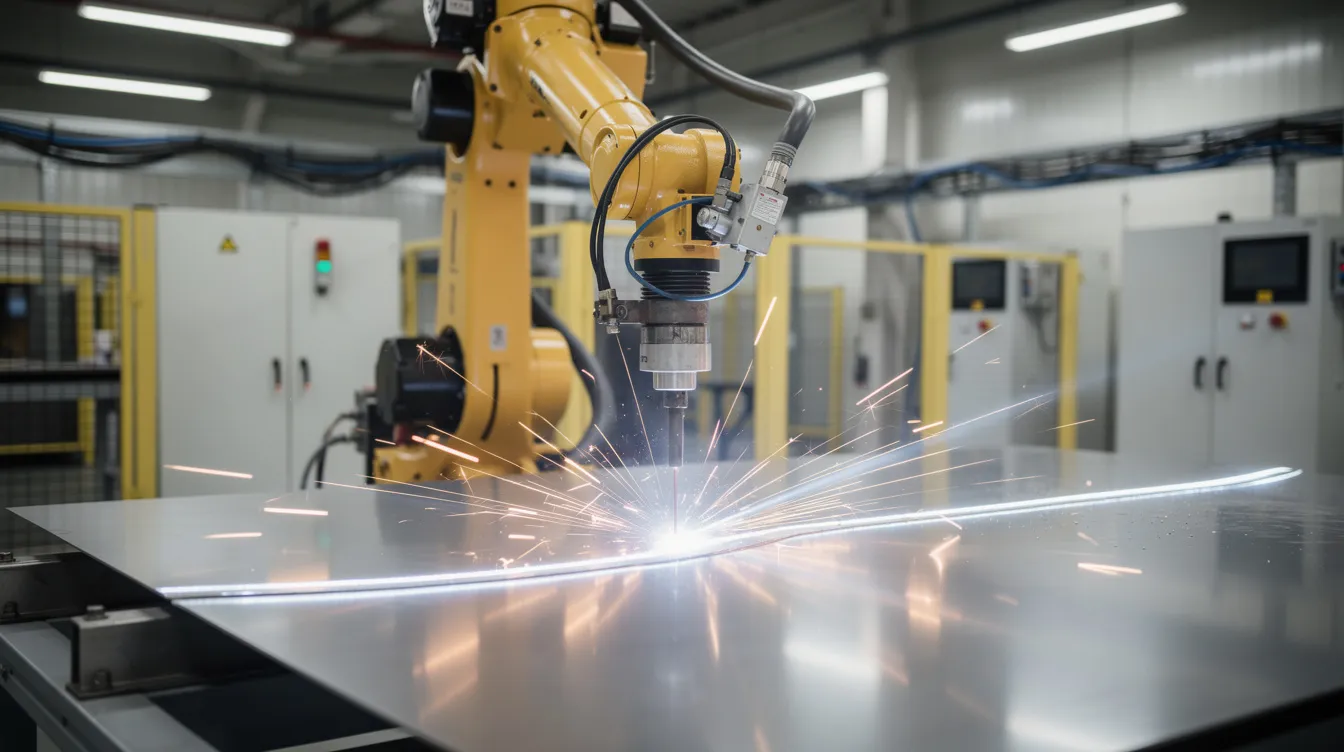
Plasma arc welding uses a constricted arc similar to TIG but achieves deeper, narrower welds, often applied to stainless steel sheet from 1–6 mm. Laser welding is a concentrated-heat welding method ideal for precision sheet metal fabrication-laser welding generates little heat distortion and produces smooth welds at high welding speed. However, laser welding requires a gap of no more than 0.005 inches, demanding excellent fixturing and part fit-up.
Electron beam welding operates in vacuum for specialized aerospace or electronics joints with extremely tight tolerances. Fiber lasers are increasingly common in EV battery tab welding and medical device hermetic sealing, reflecting a broader shift toward minimal-HAZ processes for welding thin metal.
Anebon can integrate or coordinate these advanced processes for OEM clients needing the tightest tolerances on sheet metal precision parts.
Key Factors When Selecting a Welding Method for Sheet Metal
Choosing the right welding method depends on material thickness and production speed, but the decision matrix extends further. Material type significantly influences the choice of welding process, as do joint design, welding position, and cost constraints. A perfect fit is critical when welding thin metal-proper fit-up minimizes gaps and reduces filler material needs.
For example, a 0.8 mm 304 stainless medical device cover requiring a brushed finish should be TIG welded: MIG would risk burn through and discoloration, while TIG delivers the heat control and cosmetic quality the specific welding process demands. Anebon provides DFM feedback at prototype stage to help engineers select the most cost-effective approach.
Key selection factors:
-
Material type: Conductivity, expansion rate, and oxide behavior differ across mild steel, stainless, and aluminum
-
Sheet metal thickness: Determines minimum/maximum current and suitable process
-
Joint design: Lap, butt weld, corner, and flange joints each demand different access and heat flow management
-
Welding position: Flat surface work is most stable; vertical and overhead increase difficulty
-
Production volume: Prototype favors TIG flexibility; production favors automated MIG, spot, or laser
Material Type and Material Thickness
Mild steel (~50 W/m·K conductivity) welds predictably with MIG or TIG. Stainless steel (304, 316L; ~15 W/m·K) holds heat longer, risking sensitization-TIG or laser is favored for thin gauges. Aluminum alloys like 5052 and 6061 have high thermal conductivity and oxide films, requiring more initial heat but careful control to avoid melt-through. Learn more about stainless grades in our 316 vs 316L comparison.
-
MIG welding is preferred for thicker materials over 1/8 inch in mild and carbon steel
-
TIG welding is ideal for thinner materials requiring precision, especially stainless and thin aluminum
-
Shielded metal arc welding (stick welding) becomes practical only above ~3–4 mm and is uncommon in fine sheet metal fabrication
-
Bevel edges for thicker materials around 1/8 inch to achieve proper penetration
Joint Design and Welding Position
Joint design affects the suitability of specific welding methods. Lap joints are common in spot-welded assemblies; butt weld joints demand precise fit-up and often backing support on thin sheets. Corner joints on enclosures may require TIG for tight clearance access, while flange joints on ductwork suit MIG for speed.
Well-designed joints reduce required weld size, lower heat input, and help maintain tolerances on critical dimensions-particularly important when welding sheet for assemblies that will undergo post-weld CNC machining.
Productivity, Quality, and Cost Trade-Offs
Welding speed and productivity are key factors in process selection. Robotic MIG or laser welding delivers maximum throughput, while manual TIG offers the highest cosmetic quality at lower speed. Anebon often uses a mix of processes on the same assembly-spot welded frames with TIG-finished visible corners, for example.
-
Choose MIG when: Volume is high, sheet steel is ≥ 1.0 mm, cosmetic requirements are moderate
-
Choose TIG when: Material is thin, surfaces are visible, tolerances are tight
-
Choose spot/seam when: Overlapping thin sheets in production volumes
-
Choose laser when: Minimal HAZ, hermetic seals, or exotic alloy joining is required
Surface Orientation: Flat, Horizontal, Vertical, and Overhead Welding
Even with identical material thickness and welding method, weld quality changes across positions because gravity affects the weld pool and molten metal flow. In precision sheet metal fabrication, most welding is performed on flat or horizontal surfaces using fixtures, but engineers should understand positional limits when designing parts.
Flat Surface Techniques
Flat position welding is the most stable orientation. Use a 10–20° push angle for MIG and 10–15° for TIG, maintain short arc length, and keep consistent welding speed. Flat welding allows use of backing bars (copper or aluminum) under delicate joints. Anebon uses dedicated fixtures to keep larger panels truly flat during welding.
Horizontal Surface Techniques
Horizontal welds on vertical plates risk sagging at the lower toe. Use stringer beads rather than wide weaving to limit heat input and maintain a stable weld pool. Maintain consistent torch angle and slightly faster travel speed for MIG to prevent undercut on the upper edge.
Vertical Surface Techniques
Gravity pulls the weld puddle downward, making heat concentration and control critical. Vertical-down is often preferred on very thin sheet to minimize burn through. Use shorter weld segments and the skip welding technique on vertical seams to limit distortion in tall panels.
Overhead Surface Techniques
Overhead welding is rarely used in precision sheet metal fabrication-parts are usually repositioned. When unavoidable, small weld pools, low heat input, and fast travel speeds prevent dripping molten metal. Anebon minimizes overhead welding by designing fixtures and workflows that allow flat or horizontal orientation whenever possible.
Practical Techniques to Control Heat and Distortion on Thin Sheet
Welding thin metal necessitates careful heat control to avoid burn-through, warping, and cosmetic defects-especially below ~1.5 mm thickness. Removing rust and paint from metal edges ensures a smooth and even arc, and proper cleaning of metal surfaces prevents weld defects. Clean the weld area with a wire brush or grinding wheel before welding.
Select the Right Filler Metals and Wire Size
-
Match filler metal chemistry to base metal: ER70S-6 for mild steel, ER308L for 304 stainless, ER4043 or ER5356 for aluminum alloys
-
Filler material or filler rod diameter should be equal to or smaller than base metal thickness (e.g., 0.8 mm filler for 1.0 mm sheet) to reduce excessive heat
-
Silicon bronze TIG brazing can be used on very thin steel sheet when full penetration is not required
Use Skip Welding and Stitch Welding
Stitch welding applies short, spaced welds along a joint instead of continuous welds-the skip welding technique distributes heat across the panel. Weld 20–30 mm segments with gaps, then return to fill after cooling when working on 1.0–1.5 mm sheet. This is particularly useful for cabinet doors and large enclosures where flatness tolerances are within tenths of a millimeter.
Implement Effective Tack Welding Practices
Tack welds hold metal pieces in position and lock alignment before final welding. Tack welds should be placed every inch along the joint to prevent heat buildup and gap opening. Tack welds help maintain alignment and prevent warping-Anebon plans tack sequences around critical dimensions and sometimes uses removable fixtures alongside tacks.
Choose Small Wire Diameters and Electrodes
Welding wire diameter must match sheet metal thickness. Use smaller diameter wires for better control on thin sheets-selecting the right MIG wire size is critical:
-
.023–.024 in wire for sheet ≤ 1.6 mm
-
.030 in wire for 18-gauge (1.2 mm) and above
-
1.0–1.6 mm tungsten electrode for TIG welding sheet metal at lower currents
Use Backing Bars and Heat Sinks
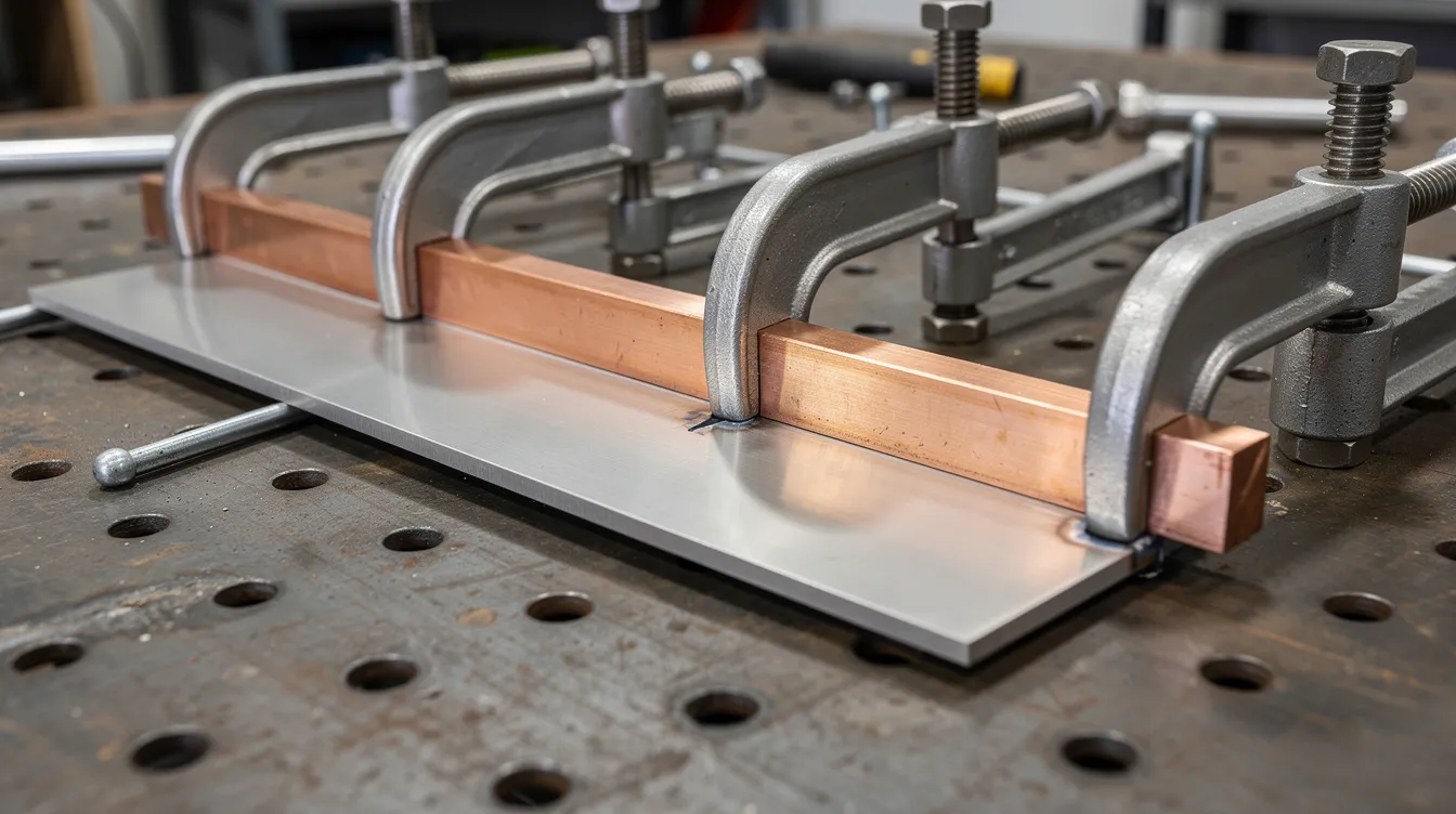
Using backing plates absorbs heat and reduces the chance of burn through. Copper or aluminum backing bars clamped behind the joint support the molten metal on open-root butt joints in 0.8–1.2 mm sheet. Proper clamping and intimate contact between backing bar and workpiece maximize heat transfer and keep critical surfaces flat.
Optimize Shielding Gas Mixtures
Use shielding gas to protect welds from atmospheric contamination. Common mixes include:
-
75% argon / 25% carbon dioxide for mild steel MIG (metal inert gas applications)
-
Argon-rich tri-mix for stainless MIG
-
100% argon for TIG on most sheet materials, including thin aluminum
High-argon mixtures produce a softer, more controllable arc with lower spatter. Balance flow rates (10–15 LPM for TIG) to protect the weld pool without causing turbulence. Anebon standardizes gas setups to maintain repeatable weld material quality.
Welding Sheet Metal in Precision OEM Production
Welding sheet metal fits into a complete fabrication workflow: laser or CNC punching, CNC bending, welding, grinding, and surface finishing. Anebon-ISO 9001:2015 and ISO 14001:2015 certified, established in 2010 in Dongguan, China-serves overseas OEMs with tight tolerance requirements on welded assemblies, including welded aluminum housings for electronics, stainless steel medical equipment frames, and mild steel machinery guards machined to ±0.002 mm.
Quality Control, Tolerances, and Surface Finish
Inspection of welded sheet metal parts includes visual checks, dimensional verification with CMM or calibrated gauges, weld size measurement, and non-destructive testing for critical joints. Weld sequence, fixture design, and controlled cooling keep assemblies within specified tolerances. Post-weld treatments include grinding and blending, deburring, powder coating, anodizing (aluminum), and passivation (stainless). Welded areas are prepared to match the finish of surrounding surfaces for a successful weld appearance.
From Prototype to Production: Choosing the Right Approach
For early-stage rapid prototyping, TIG welding may be preferred for flexibility and easy rework. As production scales, MIG, spot, or laser welding can be introduced for higher throughput. Anebon adjusts welding methods based on functional testing feedback without redesigning the entire assembly-a key advantage of working with a single partner for CNC machining, sheet metal fabrication, and welding.
FAQs on Welding Sheet Metal
What Is the Thinnest Sheet Metal You Can Weld Reliably?
-
In typical arc welding (MIG/TIG), 26-gauge (~0.5 mm) mild steel is a practical lower limit
-
Expert TIG welders can join thinner material, but with increased distortion risk
-
Below ~0.4 mm, micro-laser welding or brazing is generally preferred
Which Welding Method Is Best for Thin Sheet Metal?
-
TIG welding is usually the best choice for very thin sheet (< 1.0 mm) when precision is critical
-
MIG / gas metal arc welding can handle ~0.8–1.0 mm with correct wire diameter, shielding gas, and technique
-
For high-volume work, laser or resistance welding may be favored for speed and consistency
How Thick Can You Weld Sheet Metal with MIG or TIG?
-
Both processes handle up to ~6 mm in a single pass; above that, the weld material is typically treated as plate
-
For thicker parts, multipass metal arc welding or flux cored arc welding using flux cored wires may be more efficient
-
Anebon helps determine whether to treat a component as sheet metal or machined plate for optimal cost
Can You Use Stick (SMAW) or Flux-Cored Welding on Thin Sheet?
-
Stick welding and flux cored arc welding are generally not recommended for thin sheet metal due to high heat input and coarse penetration control
-
They become practical on thicker materials (≥ 3–4 mm) in structural or outdoor applications
-
For precision sheet metal fabrication, MIG, TIG, or resistance methods remain the right welding process
Partner with Anebon for Precision Sheet Metal Welding
Welding sheet metal successfully requires tight control of welding technique, heat input, shielding gas, and joint design across every welding project. Anebon Metal Products Limited brings over a decade of experience since 2010, ISO-certified quality systems, and advanced CNC and sheet metal fabrication equipment to both prototyping and full-scale OEM production.
Send your drawings, 3D models, or sample parts to our engineering team. We will recommend optimal welding methods and material thicknesses for your application-whether you need a single prototype or tens of thousands of welded assemblies. Contact Anebon today to request a quote and start your next precision welding project.