Essential Guide to Steel Sheet Welding Techniques and Best Practices
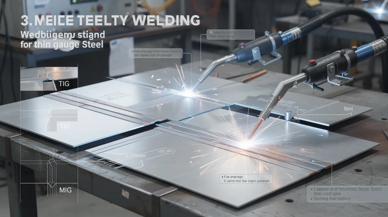
Steel Sheet Welding: Methods, Parameters, and Best Practices for Thin Gauge Steel
Introduction to Steel Sheet Welding
Steel sheet welding is one of the most demanding disciplines in metal fabrication. While welding thick plate forgives minor errors in technique, thin steel sheets amplify every mistake – a fraction of a second too long on the arc can mean a hole in your workpiece instead of a joint. Thin sheet metal typically ranges from 0.5 mm to 3 mm thick, and most fabricators classify anything under 6 mm as “sheet,” but the real process sensitivity kicks in below 3 mm.
Common alloys encountered in sheet metal welding include mild steel (A36, SPCC), galvanized zinc-coated steel, and stainless steel grades like 304 and 316L. Each brings its own welding behavior. Mild steel is forgiving; stainless has lower thermal conductivity and higher expansion; galvanized steel releases hazardous zinc fumes when heated.
The key issues when you weld sheet metal at these gauges are warping, burn through, loss of dimensional accuracy, and cosmetic defects such as discoloration or spatter on visible panels and enclosures. The main sheet metal welding methods include MIG/GMAW (short circuit and pulsed modes), TIG/GTAW, resistance spot welding, plus joint strategies like stitch welding and plug welding.
At Anebon Metal Products Limited, steel sheet welding is integrated with CNC laser cutting, punching, and bending in a unified sheet metal fabrication workflow. Upstream precision directly impacts weld quality – clean edges from laser cutting mean tighter joint fit up, less filler, and lower heat.
Why heat input control matters:
-
Thin steel sheets typically require careful heat control to avoid burn-through and warping
-
Excessive heat widens the heat affected zone (HAZ), degrading mechanical properties and appearance
-
Too much heat causes burn through; too little causes lack of fusion
-
Uneven heating produces distortion – bowing, twisting, edge pull
What Is Steel Sheet Welding? (Definition and Use Cases)
Steel sheet welding is the welding process of joining thin metal sheets by localized melting and fusion, sometimes adding filler metal, with carefully controlled heat input so that deformation stays within tolerance. Thin sheet metal is generally defined as under 6 mm thick, but the 0.8–2.0 mm range is where process control becomes especially demanding – small parameter shifts produce outsized effects on penetration and distortion.
Steel sheet welding affects:
-
Structural integrity – joints must carry design loads without cracking or fatigue
-
Stiffness – welded sheet cannot rely on mass; joint design and placement determine rigidity
-
Appearance – cabinets, enclosures, chassis, and HVAC housings require clean welds with minimal spatter
In a precision shop like Anebon, welding is planned alongside CNC cutting and bending so residual stresses remain predictable. For example, EV battery enclosure skins (1.0–1.5 mm steel) require continuous sealed welds with minimal distortion, while medical device housings often demand TIG-welded stainless at ~1.0 mm for cleanliness and aesthetics.
Core Welding Methods for Steel Sheet
Different welding methods have unique advantages and disadvantages regarding speed, precision, and heat control. The primary methods for thin sheet are:
-
MIG/GMAW short circuit – gas metal arc welding in short-circuit transfer; fast, productive, good for carbon steel up to ~2 mm
-
Pulsed MIG – alternating peak/background current for better control and lower spatter
-
TIG/GTAW – tungsten inert gas welding; slowest but highest precision and best appearance
-
Resistance spot welding – for overlapping metal sheets; extremely fast, automation-friendly
Secondary sheet metal welding techniques include stitch (intermittent) welding, plug welding, and continuous seam or fillet welding – these are joint strategies applied with any of the above processes. In a typical sheet metal fabrication workflow, metal inert gas (MIG) handles production volume while TIG handles critical visible seams. Each welding method is explored in detail below.
MIG/GMAW for Steel Sheet: Short Circuit Transfer
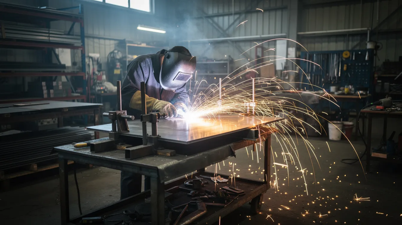
MIG welding uses a continuous wire electrode fed through a welding gun, making it the most productive arc welding process for thin sheet. In short-circuit transfer, the wire tip contacts the weld pool, shorts, deposits molten metal, then re-arcs – keeping average heat low. MIG welding is ideal for thin sheet metals up to 2 mm, and MIG welding in short circuit transfer mode is ideal for 14 gauge steel (~1.9 mm).
MIG welding is popular for sheet metal fabrication due to its high efficiency and ease of learning. Burn-through occurs when excessive heat melts completely through thin metal, so parameter control is critical.
Starting parameter ranges for mild steel:
|
Sheet Thickness |
Current (A) |
Voltage (V) |
Wire Diameter |
|---|---|---|---|
|
0.8 mm |
40–70 |
16–18 |
0.8 mm |
|
1.0 mm |
50–90 |
17–19 |
0.8–0.9 mm |
|
1.5–2.0 mm |
70–110 |
18–20 |
0.9 mm |
Best practices for mig welders on thin sheet:
-
Use the smallest suitable wire diameter to reduce heat input
-
Maintain short arc length – almost touching the work
-
Increase travel speed while watching for full fusion
-
Use intermittent welds instead of continuous runs where possible
-
Support metal pieces with fixtures to prevent movement
Pulsed MIG for Thin Steel Sheet
Pulse MIG alternates between high peak current (for droplet detachment) and low background current (for cooling). Pulse welding reduces average heat input while maintaining penetration, and pulse MIG welding minimizes spatter and improves control over bead appearance.
Recommended shielding gas mixes for pulse on thin carbon steel: 90–95% argon with 5–10% carbon dioxide. Higher argon content softens the arc, reducing spatter and heat. Modern synergic machines adjust pulse timing, voltage, and wire feed in coordinated curves – giving consistent results across 0.8–3.0 mm steel sheet.
When to select pulsed MIG over short-circuit:
-
Visible joints where bead appearance matters
-
Stainless or coated steel where low heat input is critical
-
Material thickness above ~1.2 mm where short-circuit may lack adequate fusion
-
Production environments where minimizing post-weld cleanup saves cost
Technique tips: use a push angle on the welding gun, maintain steady travel speed, and avoid stepping back into the weld pool.
TIG Welding (GTAW) Thin Steel Sheet
TIG welding provides superior quality for thin materials and is preferred for high-quality, visible seams on stainless and carbon steel sheet. The process uses a non consumable tungsten electrode, a separate filler rod (when needed), and argon-based shielding gas to produce clean welds with almost zero spatter.
TIG welding produces the highest quality welds for thin materials and allows autogenous welding (no filler material) on very thin sections as low as 0.6–1.0 mm. TIG welding provides superior control for thin materials because the experienced welder modulates current with a foot pedal, maintaining precise control over the weld pool at all times.
Trade-offs: slower travel speed, higher operator skill requirements, and higher cost per meter compared with MIG. TIG welders must maintain tight arc discipline and welding position consistency.
Recommended settings for stainless steel sheet:
-
1.0 mm stainless: 40–60 A, tungsten electrode 1.6 mm, filler rod 1.0 mm, argon at 8–10 L/min
-
2.0 mm stainless: 70–100 A, tungsten 1.6–2.4 mm, filler rod 1.6 mm, argon at 10–12 L/min
Both mig and tig welding play complementary roles – MIG for volume, TIG for precision and appearance.
Resistance Spot Welding of Steel Sheet
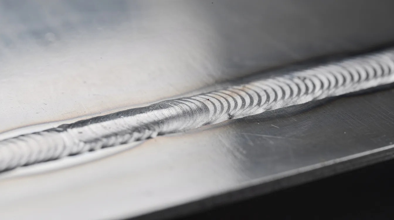
Spot welding joins overlapping metal sheets by passing current between copper electrodes under pressure, creating a molten nugget without filler metal. Resistance spot welding is very fast and ideal for overlapping joints in automotive body panels. Spot welding is commonly used in automotive manufacturing for body-in-white assembly.
Design norms: nugget diameter should approximate 5 × √t, where t is individual sheet thickness in mm. For two 1.0 mm sheets, that yields a ~5 mm nugget. Electrode tip diameter is typically slightly larger – around 6 mm for 0.5–1.25 mm sheets.
Spot welding is ideal for joining thin sheet metals quickly. Anebon may specify spot welding instead of seam or fillet welding when:
-
Joints are lap joints with overlapping flanges
-
Cycle speed matters more than continuous sealing
-
Minimal visible weld marks are acceptable (e.g., interior enclosure flanges)
-
The design allows spot welding over riveting for strength
Other Joint Strategies: Stitch, Plug, and Seam Welding
-
Stitch welding – short weld segments with gaps between them. Stitch welding reduces cumulative distortion in thin sheet metal by allowing cooling between each segment. Stitch welding reduces heat buildup and minimizes distortion, making it ideal for long seams on thin panels.
-
Plug welding – a hole is drilled in one sheet, then filled with weld to fuse to the underlying sheet. Hole diameter is small relative to material thickness; spacing is determined by load requirements.
-
Continuous seam/fillet welding – provides full sealing for fluid tanks and sealed electronics housings but produces the highest cumulative heat and worst-case distortion.
-
Choosing between them – intermittent welds reduce heat and distortion; continuous welds add stiffness and sealing. Specify the correct joint technique on drawings with proper weld symbols, stitch length, gap, and hole diameter.
Materials: Mild, Stainless, and Galvanized Steel Sheet
Mild steel offers the best weldability and is the most forgiving base material for general enclosures, brackets, and structural frames. It has moderate thermal conductivity and relatively low thermal expansion.
Stainless steel (304, 316L) has roughly 40–50% the thermal conductivity of mild steel and higher thermal expansion. Overheating causes sensitization (carbide precipitation), loss of corrosion resistance, and discoloration. Use “L” grades, proper filler metal (ER308L, ER316L), 100% argon shielding, and pulsed modes to limit heat.
Galvanized steel presents unique challenges: zinc vaporizes at welding temperatures, causing porosity, poor bead quality, and hazardous fumes. Surface preparation around the weld area is critical – remove zinc coating where possible, ensure ventilation, and adjust gas mixes accordingly.
Surface Preparation and Joint Fit-Up
Proper joint preparation includes removing rust and contaminants to ensure quality welds. Pre-weld preparation is non-negotiable.
-
Remove oil, grease, mill scale, paint, and heavy rust from the weld area using a wire brush, grinding, or chemical cleaning
-
For stainless steel, use a dedicated stainless wire brush and acetone wipe; never use carbon steel brushes that contaminate the oxide layer
-
Pre-weld preparation includes cleaning the oxide layer from aluminum and similarly removing surface oxides from steel before welding
-
Edge preparation must produce clean, square edges with minimal gaps – large gaps increase required heat and risk burn through
-
Use precision CNC fabrication (laser cutting, punching, bending) for consistent edges and tight joint fit up
-
Apply frequent small tack welds to maintain alignment before final welding
Controlling Heat Input in Steel Sheet Welding
Heat input measures energy per unit length of weld (kJ/mm). Heat management is crucial for achieving strong welds in thin sheet metal to prevent burn-through and warping. To control heat input:
-
Lower amperage and voltage to reduce energy delivered per unit time
-
Increase travel speed to reduce dwell time at any point
-
Use smaller wire diameter for lower deposition and less heat per pass
-
Select short-circuit or pulsed transfer modes instead of spray
-
Apply intermittent welds – a continuous weld on 1.2 mm steel can deliver double the cumulative heat of an equivalent-length stitch weld pattern
Low heat input limits burn-through and warping but must still ensure adequate penetration. The goal is always the narrowest possible window: enough to fuse, not enough to deform.
Parameter Selection: Amperage, Wire Diameter, and Travel Speed
Lower amperage settings help prevent burn-through in thin materials. Use smaller diameter filler wire for better control on thin sheets – typically 0.6–0.8 mm solid wire for carbon steel sheet under 2.0 mm.
Setup approach:
-
Start with manufacturer parameter charts for the specific wire and base material
-
Test on scrap sheet of the same gauge and material
-
Adjust amperage downward if you see excessive penetration or warping
-
Increase travel speed to reduce bead width and heat – but watch for lack of fusion
-
Using smaller diameter filler wire improves control on thin materials by reducing deposition rate
Travel speed interacts directly with current: slower travel increases heat per unit length, faster travel risks incomplete fusion. For manual welding, expect 300–600 mm/min depending on thickness and joint geometry.
Shielding Gas Choices for Steel Sheet Welding
Shielding gas protects the weld pool and molten metal from atmospheric contamination. Common options for steel sheet:
-
100% carbon dioxide – deep penetration, low cost, but high spatter and aggressive arc; not ideal for thin sheet
-
75/25 or 80/20 Ar/CO₂ – balanced penetration and reduced spatter; standard for carbon steel MIG
-
90/10 or 95/5 Ar/CO₂ – softer arc, lower heat, better for thin sheet and pulsed modes
-
Pure argon – standard for TIG on both carbon and stainless steel; also used as inert gas in specialized MIG applications
Consistent gas flow (8–12 L/min for TIG) and correct nozzle size prevent porosity. Turbulence or drafts disrupt shielding and cause oxidation on thin seam welds.
Welding Techniques to Protect Thin Materials
Using shorter welds and cooling techniques helps to manage heat and reduce distortion in sheet metal. Practical welding techniques include:
-
Skip welding – weld short lengths, skip ahead, return to fill gaps; distributes heat evenly
-
Back-stepping – weld segments in reverse sequence to counteract directional distortion
-
Alternate weld locations – balance both sides of a panel so contraction forces offset each other
-
Tack welding – tack welding can align joints before making the final weld, minimizing distortion during the process
-
Backing bars – copper or aluminum bars placed behind the joint absorb heat, support the weld pool, and prevent burn through on edges
-
Stringer beads – favor straight, quick passes over wide weave patterns; weaving slows travel speed and increases heat
Proper technique with any of these methods will minimize distortion and protect thin sheet from excessive heat buildup.
Managing Distortion and the Heat Affected Zone (HAZ)
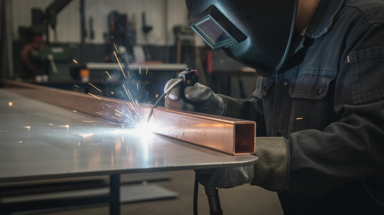
The HAZ is the region adjacent to the weld where the base material’s microstructure is altered by heat without melting. In thin steel, even a slightly oversized HAZ can cause grain growth, reduced toughness, and – in stainless – loss of corrosion resistance. Warping is caused by uneven heating during welding.
Common distortion patterns: panel bowing, twisting, and edge pull. Strategies to control HAZ and minimize distortion:
-
Keep heat input as low as practical
-
Plan a balanced welding sequence – weld symmetrically, alternate sides
-
Use fixtures and clamps to restrain movement
-
Allow cooling between weld passes; monitor interpass temperature
-
Design stiffening features (flanges, hems, ribs) into parts to resist contraction
For welded enclosure frames, using intermittent welds along edges instead of continuous seams can reduce panel pull enough to maintain assembly fit within ±0.5 mm tolerances.
Safety Considerations in Steel Sheet Welding
Thin sheet welding safety risks are amplified because heat penetrates quickly and coatings vaporize readily. Key precautions:
-
Wear an auto-darkening welding helmet (correct shade), leather gloves, flame-resistant clothing, safety glasses, and proper footwear
-
Use local fume extraction, especially when welding galvanized steel or stainless (chromium/nickel fumes)
-
Keep a fire extinguisher within arm’s reach – hot spatter can ignite flammable materials behind thin metal panels
-
Ensure proper ventilation when using high carbon dioxide gas mixes
-
Train welders on arc length control, foot pedal modulation, and welding position safety for thin gauge work
-
Follow OSHA, EN ISO, or local equivalent safety standards
Quality Control and Inspection of Steel Sheet Welds
Acceptance criteria for steel sheet welds typically include:
-
Consistent bead width and profile
-
Full penetration without burn through or undercut
-
Absence of porosity, cracking, and excessive spatter
-
Dimensional accuracy – flatness, straightness, and geometry within tolerance
-
Surface appearance, especially on visible stainless or painted panels
Inspection methods:
-
Visual inspection with fillet gauges and welding calipers
-
Dye penetrant testing for critical stainless welds (medical, food equipment)
-
Destructive macro-etch on sample welds during process validation
-
Documentation of weld procedure specifications (WPS) and welder qualifications
Anebon’s ISO 9001:2015 quality system ties welding parameters, welder IDs, and inspection records to full OEM part traceability.
Automation and Advanced Welding Solutions
Robotic MIG and spot welding deliver repeatable travel speed, consistent arc conditions, and precisely controlled heat input for high-volume production. Automated welding cells integrated with CNC punching and laser cutting streamline fabrication – parts move directly into welding fixtures, preserving fit-up quality.
Advanced inverter-based power sources maintain stable arcs at very low amperage, critical for welding thicker materials down to sub-1 mm sheet. Technologies like cold metal transfer (CMT) and surface tension transfer (STT) are specialized short-arc variants designed for thin sheet.
Laser welding offers minimal distortion and excellent automation for high-precision manufacturing. Its ultra-narrow HAZ and high speed make it suitable for sealed cosmetic seams, though it requires gap tolerances under 0.1 mm and significant capital investment.
Flux-cored arc welding uses a tubular wire filled with flux that can be gas-shielded or self-shielded, and while less common on thin sheet, it has niche applications in heavier gauge structural sheet work.
Anebon leverages these technologies to serve overseas OEMs needing repeatable, high-volume steel sheet welding with better control over quality and cost.
Design for Manufacturability (DFM) in Steel Sheet Welded Parts
Early DFM input reduces cost and improves weld quality. Guidelines for design engineers:
-
Favor lap joints and corner joints over butt joints – they are easier to weld on thin steel and more forgiving of fit-up variation
-
Design flanges wide enough for electrode or welding gun access
-
Specify intermittent welds where full-length seams are not structurally or sealing-required – this limits heat input
-
Define hole size and spacing for plug welds; define stitch weld length and gap clearly on drawings
-
Consider material thickness early – thinner is lighter but harder to weld without distortion
-
Anebon’s DFM consulting advises on practical tolerances and weld symbols compatible with available fixtures and welding methods
Typical Applications of Steel Sheet Welding in OEM Manufacturing
Key industries and applications:
-
Automotive and EV – MIG welding is commonly used in automotive manufacturing for body panels and brackets; spot welding for body-in-white; continuous seam welds for EV battery module frames requiring fluid sealing
-
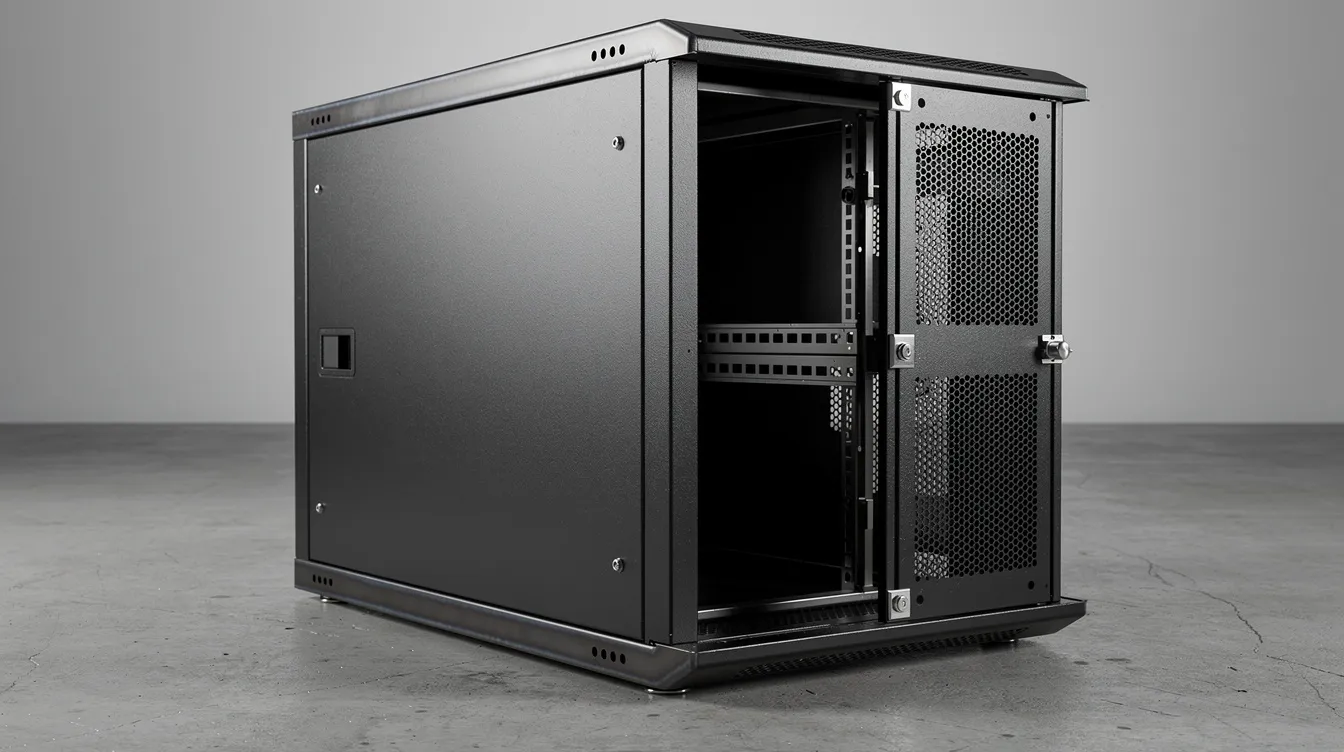
Electronics – welded steel racks and server cabinets using MIG stitch welds for structure
-
Medical devices – TIG-welded stainless enclosures and housings where clean welds and surface finish are mandatory
-
Industrial machinery and robotics – robotic arm housings, control enclosures, precision sheet metal fabrication for functional assemblies
-
Telecom – outdoor enclosures welded for sealing and stiffness
Anebon supports both rapid prototyping (manual TIG or MIG) and full-scale production (robotic MIG, spot welding) from its Dongguan facility, serving as a one-stop precision sheet metal fabrication partner.
Working With Anebon Metal Products Limited
-
Full-service capabilities: CNC laser cutting, punching, bending, steel sheet welding (MIG, TIG, spot), surface treatment, and assembly
-
ISO 9001:2015 and ISO 14001:2015 certified; serving overseas OEM clients since 2010
-
Typical engagement: design review with DFM feedback → prototype build → welding process validation → production scale-up
-
Materials supported: mild steel, stainless steel, galvanized steel, aluminum, and specialty alloys
-
Request a quote or share drawings and CAD files for evaluation of welding feasibility, cost, and lead time
Key Takeaways and Next Steps
-
Choose the right welding method for your material thickness, joint type, and quality requirements – MIG for production speed on carbon steel, TIG for visible stainless seams, spot welding for overlapping lap joints
-
Control heat input through lower amperage settings, higher travel speed, smaller wire, and intermittent weld patterns to prevent burn through and minimize distortion
-
Invest in surface preparation and tight joint fit up – precision upstream processes (laser cutting, CNC bending) pay dividends at the welding station
-
Apply DFM principles: design joints for access, specify intermittent welds where continuous seams aren’t needed, and select material thickness appropriate for both function and weldability
-
Partner with a certified precision fabricator like Anebon Metal Products Limited for complex or high-precision steel sheet welding projects – from prototype to production, with full traceability and quality assurance