Essential Guide to Sheet Metal Fabrication Techniques and Processes
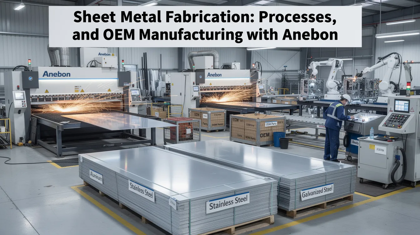
Sheet Metal Fabrication: Processes, Materials, and OEM Manufacturing with Anebon
Introduction to Sheet Metal Fabrication
Sheet metal fabrication transforms flat metal sheets into precise, functional parts through a sequence of cutting, forming, joining, and finishing operations. Common processes include cutting, bending, and welding-each chosen based on the geometry, material, and performance the final part demands. For OEMs navigating tightening supply chains and rising material costs between 2024 and 2026, mastering this versatile manufacturing process is more relevant than ever.
Sheet metal fabrication is essential in industries such as automotive, aerospace, electronics, and construction, where engineers need metal components that combine structural integrity with tight dimensional control. It is also a cost-effective method for producing small and large volumes of parts, from one-off prototypes to tens of thousands of identical units per month.
Anebon Metal Products Limited, founded in 2010 and headquartered in Dongguan, China, serves overseas OEMs with end-to-end metal fabrication services-from rapid prototyping through full scale production. Holding ISO 9001:2015 and ISO 14001:2015 certifications, Anebon delivers sheet metal parts such as enclosures, brackets, chassis, medical housings, aerospace brackets, and industrial machinery panels with tolerances as precise as ±0.002 mm on CNC-machined features.
This sheet metal guide walks design engineers through every stage-from material selection and CAD design to cutting, forming, finishing, and quality control-so you can make informed decisions before your next project hits the shop floor.
Overview of the Sheet Metal Fabrication Process
The sheet metal fabrication process follows a clear sequence: concept → CAD design → DFM review → material selection → nesting → cutting → forming → secondary operations → surface finishing → inspection → packaging and shipment. Each stage feeds the next, and catching errors early-especially at the design and DFM review steps-saves weeks and significant cost downstream.
A typical project starts with a parametric 3D CAD model that includes flat patterns, bend lines, and hole locations. During the DFM review, engineers check minimum bend radii, interference between features, and whether specified tolerances match the fabricator’s actual machine capabilities. Material thickness choice, nesting layout on standard sheet sizes, and the cutting method are then locked in before metal is touched.
Anebon typically moves OEM parts from 3D CAD to finished assemblies in days to a few weeks, depending on complexity and volume. Rapid prototyping of 1–50 pieces using CNC technology for sheet metal components allows engineers to validate fit, form, and function before committing to tooling. High volume production runs of hundreds to tens of thousands of pieces require stable processes, repeatable tooling, and documented quality plans. Precision metal fabrication offers design flexibility through processes such as laser cutting and stamping, making it practical for both scenarios.
Sheet Metal Materials and Material Selection
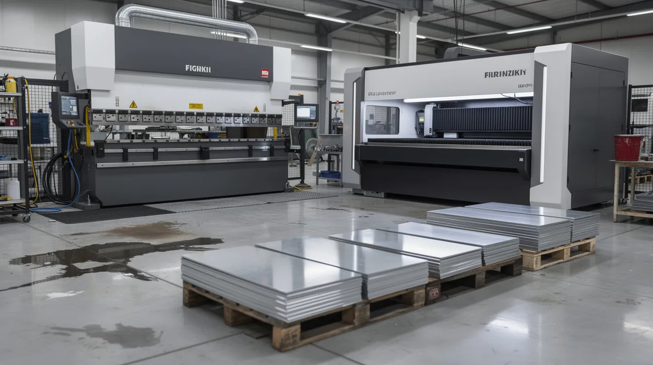
Choosing the right sheet metal materials defines nearly every downstream decision: bend radius, weldability, corrosion resistance, weight, cost, and surface finish options. Common metals used in sheet metal fabrication include steel, aluminum, stainless steel, copper, and brass-each suited to different operating environments.
Here is how the most frequently specified raw materials compare:
-
Cold rolled steel (e.g., ASTM A366 / DC01): affordable, smooth surface, easy to form. Needs coating or plating for corrosion protection. Ideal for painted enclosures and brackets.
-
Hot rolled steel (e.g., A36): thicker gauges, rougher finish, looser thickness tolerances. Common for structural frames and heavy industrial machinery panels where aesthetics are secondary.
-
Galvanized steel: cold or hot rolled steel pre-coated with a corrosion resistant layer of zinc; a practical middle ground when parts face moisture but don’t justify stainless steel pricing.
-
Stainless steel (304, 316L): used for its corrosion resistance and strength. 316L is the go-to for marine, medical, and food-grade applications. Higher springback and cost than mild steel.
-
Aluminum alloys (5052-H32, 6061-T6): aluminum is lightweight and corrosion-resistant, ideal for transport and aerospace. 5052 offers better formability; 6061 delivers higher strength but requires careful bend radii.
-
Copper and brass: copper is often used for electrical applications due to its good conductivity properties, as well as EMI/RFI shielding. Brass serves decorative elements and connectors.
-
Titanium: used in the aerospace industry for its high strength-to-weight ratio, though it demands specialized cutting and forming equipment.
Typical material thickness ranges for most Anebon sheet metal parts fall between 0.5 mm and 6 mm, with some laser-cut plates reaching ~10 mm. Practical examples: 1.2 mm 304 stainless for medical enclosures, 2.0 mm 5052 aluminum for automotive brackets, and 3.0 mm mild steel for industrial machinery frames. Sheet metal fabrication can produce lightweight components with high strength-to-weight ratios when designers pair the right alloy with the right gauge.
Key material selection criteria include strength, stiffness, weldability, electrical conductivity, weight, and cost. Anebon provides engineering support to compare materials for specific industries-helping teams decide, for example, whether 316L or hard-anodized 6061 is the better fit for a medical housing, or whether galvanized steel outperforms powder-coated cold rolled steel for an outdoor consumer electronics enclosure.
From Idea to Sheet Metal Design (CAD & DFM)
Sheet metal design begins with a functional idea-an enclosure that must shield electronics, a bracket that carries a defined load, a chassis that mates with twelve other parts. That idea becomes a parametric 3D CAD model (SolidWorks, Creo, Inventor) with flat patterns that define every bend line, cutout, and hole.
Critical design parameters include:
-
Material thickness and its effect on bend calculations.
-
Minimum bend radii, which depend on alloy and temper (e.g., ≈1× thickness for aluminum, 1–1.5× for steel).
-
Bend allowance and K-factor for computing accurate flat patterns.
-
Hole-to-edge distance ≥ 2× material thickness to prevent tear-out.
-
Hole-to-bend-line distance ≥ 2.5× thickness plus the bend radius.
-
Relief cuts at bends: width ≥ thickness, depth > radius + thickness, to avoid tearing.
Sheet metal can be formed into complex shapes using brakes, but only if the design respects these constraints. Anebon’s DFM feedback-automated checks plus experienced engineer review-catches unformable bends, impossible tolerances, and interference before the manufacturing process begins.
Practical guidance: keep minimum flange length ≥ 3 × material thickness; avoid slots narrower than the laser kerf; align bends with grain direction when working with aluminum to reduce cracking risk. Well-prepared engineering drawings should specify tolerances (e.g., ±0.1 mm general per ISO 2768-m, tighter where functionally required), desired surface finish (anodized, powder coat, chem film), and inspection criteria.
Cutting Processes: Laser Cutting and Other Methods
Cutting is the first major step in most metal fabrication processes, converting flat metal sheets of uniform thickness into blanks ready for forming. Cutting processes include laser cutting, plasma cutting, waterjet cutting, and mechanical shearing-each with distinct advantages.
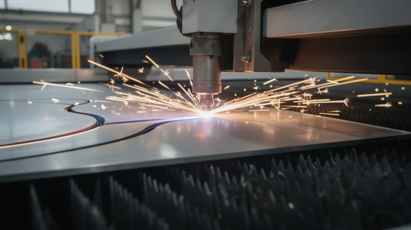
Laser cutting is the workhorse for precision sheet metal work. A fiber laser cutter directs a focused beam through a cutting head that traces complex profiles at high speed. Laser cutting can achieve precision of +/- 0.1 mm on sheet metal, with a minimal heat-affected zone that preserves material properties near the cut edge. It excels on intricate contours-control panels with dozens of cutouts, RF shields, decorative grills-and handles thicknesses from roughly 0.3 mm up to about 10 mm for steel and aluminum in everyday production. Laser cutting can cut metals up to 30 mm thick with high-power systems, though edge quality and speed decrease beyond ~10 mm.
Plasma cutting is effective for conductive materials only and handles thicker gauges quickly, making it useful for structural plate work where edge finish is secondary. Waterjet cutting can handle materials up to 300 mm thick and introduces zero heat, making it ideal for heat-sensitive alloys like titanium-but it is slower and more expensive per cut. Mechanical cutting uses physical tools to cut sheet metal and remains the fastest option for long, straight edges, though it offers fewer geometric options.
Automated nesting software optimizes blank layout to reduce scrap on complex contoured parts, directly lowering material cost. Anebon primarily uses laser cutting for sheet metal fabrication because it fits tight-tolerance OEM work, but combines it with punching or stamping on request for high volume production runs.
Forming and Bending of Sheet Metal
Metal bending turns flat blanks into three-dimensional geometry. Bending is a common forming process that uses a press brake machine to fold metal along a programmed line, creating flanges, channels, and enclosures from a single piece.
Press brake basics: a punch descends into a V-die, forcing the sheet to the desired angle. The inside radius, tooling selection (V-die width, punch nose radius), and material properties determine whether the bend succeeds or cracks. Springback-the elastic recovery that makes the actual angle slightly less than the punch setting-must be compensated in the program or tooling.
Guidelines tying bend radius to material thickness:
-
Aluminum (6061-T6, hard temper): minimum inside radius ≈ 1× thickness.
-
Mild steel: ≈ 1× thickness.
-
Stainless steel (304, 316L): 1–1.5× thickness due to higher strength and springback.
Anebon maintains angular accuracy to ±0.5° on precision work and handles multiple bends per piece, though each added bend contributes to tolerance accumulation. For best results, avoid closely spaced bends that tooling cannot physically reach, keep holes away from bend lines (≥ 2.5× thickness + radius), and consider grain direction for aluminum to prevent cracking.
Advanced forming operations-hemming for safe edges, joggles for panel offsets, louvers for airflow, and embossing for stiffness or branding-extend what the fabrication process can deliver from a single blank.
Punching, Hardware Insertion, and Other Fabrication Operations
Punching complements laser cutting when a design calls for repetitive holes and special shapes. Punching creates holes in sheet metal using a punch tool driven through a die, and CNC turret punching can produce ventilation patterns, louvers, dimples, and large batches of standard holes at speed.
Punching is more economical than laser cutting when volumes are high, features repeat across many metal pieces, or gauges are thick enough to slow a laser cutter. For small runs with many tool changes, laser cutting typically wins on cost and turnaround.
Hardware insertion adds PEM nuts, self-clinching standoffs, and threaded fasteners directly into sheet metal components-critical for electronics enclosures and chassis where mounting plates need reliable threaded interfaces. Each insert type has a minimum sheet thickness requirement (the sheet must be thick enough for cold-flow clinching) and a minimum edge distance.
Secondary machining rounds out the workflow: countersinking, tapping, and light CNC milling on formed parts create precision interfaces that bending alone cannot achieve. Anebon can combine laser cutting, punching, and CNC machining in one workflow to meet tight functional requirements-this subtractive manufacturing process approach removes material only where needed, keeping cost and lead time low.
Joining and Assembly: Welding, Riveting, and Fastening
Assembly turns separate sheet metal parts into finished products or subassemblies. The joining method chosen depends on material, load, disassembly needs, and cosmetic requirements.
Welding joins metal parts by melting edges together, sometimes with a filler material added to the joint. TIG welding uses a non-consumable tungsten electrode and is preferred for thin stainless steel and aluminum where bead appearance and heat control matter. MIG welding feeds a continuous wire electrode through a gun, offering faster deposition on thicker gauges. Spot welding fuses overlapping thin-gauge steels at discrete points and is common in automotive panels. Among other welding techniques, brazing bonds workpieces using a filler metal above 450°C for joints that need less heat input than fusion welding, while soldering occurs at temperatures below 200°C and suits delicate electrical connections.
Common joining methods also include riveting, bolts, screws, and adhesive bonding-each useful where heat must be avoided or future rework is anticipated. Riveting uses cylindrical pins to join metal parts and remains standard in aerospace structures where fatigue performance is critical.
Design tips for robust assemblies: provide sufficient lap length for welds, design tabs and slots for self-location, and anticipate weld distortion in thin materials by fixturing parts securely. Anebon supplies fully assembled units for OEMs, including integration of machined parts, die castings, and off-the-shelf components when required. Quality controls during assembly include fixture use, jigs, and in-process dimensional checks on critical interfaces.
Surface Finishes: Powder Coat, Chem Film, and More
Surface finishing is the final step that determines a part’s corrosion resistance, wear performance, electrical conductivity, and appearance. Finishing includes treatments like powder coating, anodizing, and deburring to enhance durability. Here are the most commonly specified options:
-
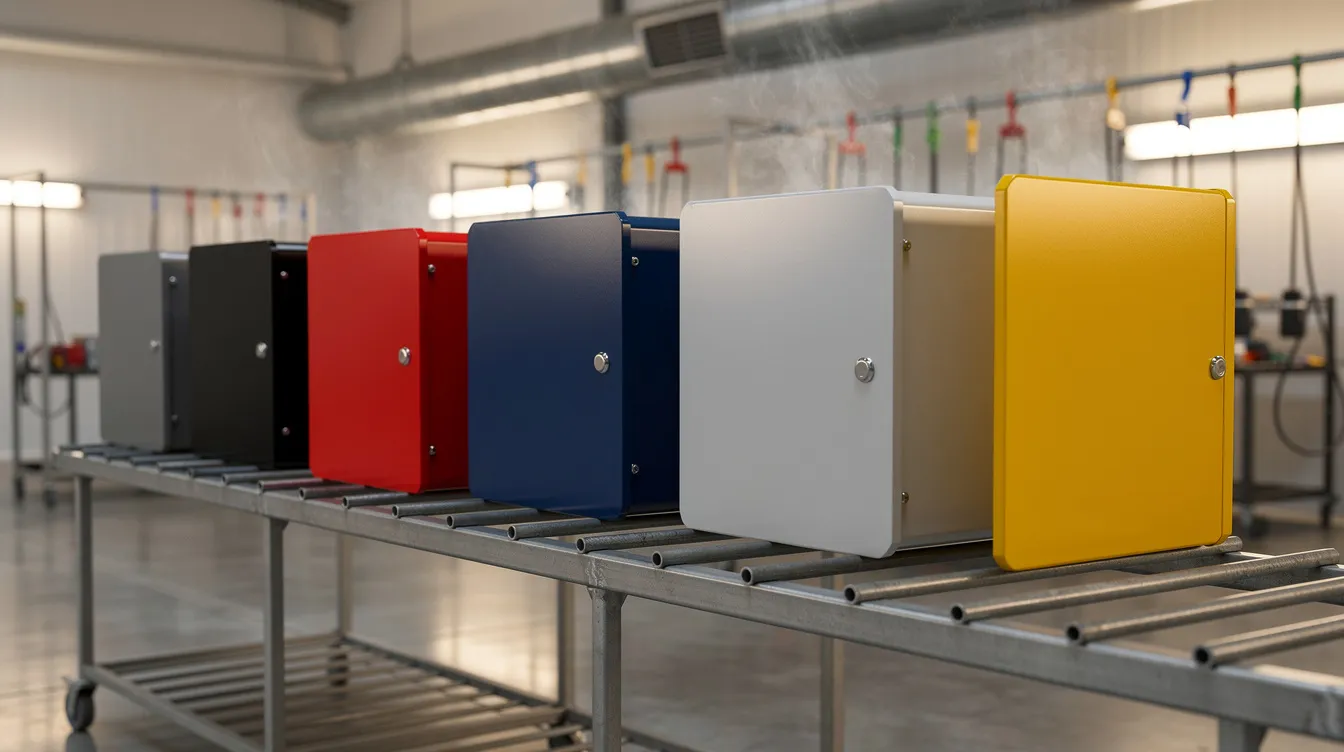
Powder coating: powdered paint is applied electrostatically and baked to cure, forming a durable, wear resistant layer typically 50–100 µm thick. Available in a wide range of RAL colors, it outperforms standard painting methods in chip and scratch resistance. Ideal for industrial enclosures, racks, and consumer electronics housings.
-
Chromate conversion coating (chem film): applied to aluminum, this thin corrosion resistant finish adds very little thickness-about 0.00001″ to 0.00004″-while preserving electrical conductivity. It meets standards like MIL-DTL-5541 and serves as an excellent base for further processing such as painting.
-
Anodizing: Type II anodizing creates a corrosion-resistant finish suitable for decorative and moderate-wear applications. Type III (hard anodize) delivers a thicker, harder coating for demanding environments. Anodizing can produce layers from 0.0025 mm to 0.05 mm thick, depending on type and specification.
-
Electroplating: electroplating deposits a thin layer of metal-nickel, tin, zinc-on surfaces for conductivity, solderability, or appearance.
-
Mechanical finishes: bead blasting (using plastic beads or glass media), brushing, and polishing prepare surfaces or create specific textures. Passivation on stainless steel removes free iron and enhances the natural corrosion resistant layer.
Choosing a finish depends on the operating environment. Marine or medical parts often require 316L stainless or hard-anodized aluminum. Electronics benefit from chem film to maintain good conductivity properties. General industrial parts perform well with powder-coated mild steel or aluminum. Heat treatment may also be specified before finishing when parts require stress relief or hardened surfaces.
Design Guidelines: Material Thickness, Tolerances, and Cost Drivers
Good sheet metal design reduces cost and lead time without sacrificing function. A few rules of thumb go a long way.
Matching thickness to load:
|
Part Type |
Typical Thickness |
Example |
|---|---|---|
|
Small covers, light shields |
0.8–1.2 mm |
Instrument panel covers |
|
Brackets, mounting plates |
1.5–2.5 mm |
Motor mounts, sensor brackets |
|
Structural frames, base plates |
≥ 3 mm |
Machine frames, storage tanks |
Tolerances: Standard sheet metal tolerances per ISO 2768-m (±0.15 mm for linear dimensions in the 3–30 mm range, ±0.5° angular) cover most commercial work. Tighter tolerances increase cost through additional setups, machining, and higher rejection rates. Anebon can reach ±0.002 mm on CNC-machined features when needed, but for bent and welded dimensions, ±0.25 mm per bend is a practical baseline. Understanding warping and tolerance challenges is a critical aspect of scaling production.
Cost drivers: number of setups and unique bends, complex weldments, non-standard finishes, exotic sheet metal materials (titanium, Inconel), and small lot sizes all push unit cost upward. High strength materials require heavier tooling and slower cycle times.
Practical tips to cut cost:
-
Standardize material thickness across an assembly to reduce inventory and simplify tooling.
-
Combine parts where possible to lower part count and assembly labor.
-
Avoid unnecessary cosmetic finishes on hidden faces.
-
Design for efficient nesting on standard raw sheet sizes.
-
Specify the desired shape clearly in CAD to minimize back-and-forth.
Anebon’s engineers routinely help customers optimize for manufacturability before locking toolpaths and fixtures-catching cost issues at the design stage rather than on the shop floor.
Applications Across Industries
Sheet metal fabrication underpins products across the aerospace industry, medical devices, automotive, electronics, robotics, and industrial machinery. Applications for sheet metal fabrication include automotive body panels, aerospace structures, and HVAC ductwork-and that only scratches the surface. Over 50% of car parts are made from sheet metal, underscoring just how central this manufacturing process is to modern industry.
Concrete examples:
-
19″ rackmount server chassis for data centers-dozens of cutouts for connectors, ventilation, and mounting hardware.
-
EV battery enclosures requiring sealing, thermal stability, and corrosion protection.
-
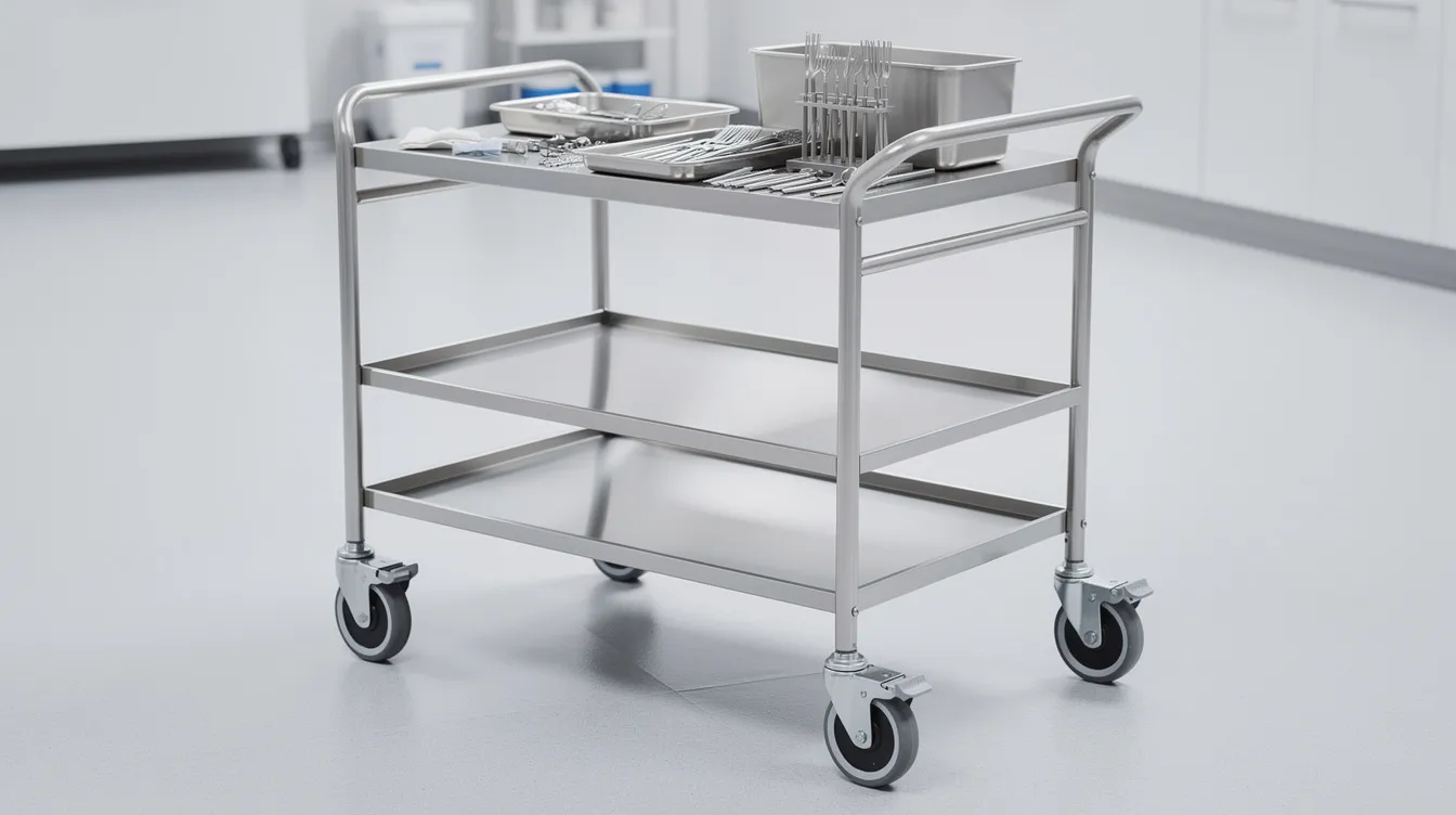
Surgical instruments trays and equipment carts cleaned daily with harsh disinfectants-316L stainless or electropolished 304 is standard.
-
Drone frames where weight savings from aluminum directly extend flight time.
-
HVAC housings with louvered vents, formed stiffeners, and powder-coated mild steel.
-
Machine safety guards protecting operators around CNC machining centers and industrial equipment.
Durability and protection against environmental conditions are key benefits of fabricated metal enclosures, whether shielding sensitive consumer electronics from EMI or protecting outdoor electrical gear from rain and UV. Custom sheet metal solutions from Anebon pair tailored material selection with the right finish: 316L stainless for medical, anodized 6061 for aerospace brackets, powder-coated steel for factory automation. Sheet metal fabrication often integrates with CNC machining and die casting within one OEM product, and Anebon can supply all three.
Quality Assurance and Inspection in Sheet Metal Fabrication
OEMs expect repeatable quality from every batch. ISO 9001:2015 certification ensures quality management standards are documented, followed, and continuously improved. Anebon also holds ISO 14001:2015 for environmental management-increasingly important for overseas OEMs with sustainability mandates.
Inspection stages:
-
Incoming materials: verify thickness, flatness, and material certificates against order specs. Gauge variation in raw materials is real-14-gauge cold rolled steel can legally vary from ~1.79 mm to ~2.00 mm.
-
In-process: dimensional checks after cutting and after bending catch drift before it compounds. Visual inspection identifies defects before further processing, saving rework on downstream operations.
-
Final audit: full dimensional inspection against engineering drawings, cosmetic review, and functional checks (door closure, hinge operation, mounting hole alignment).
Tools and methods:
-
Calipers, micrometers, and height gauges for linear dimensions. Dimensional inspection uses tools like micrometres for accuracy on critical features.
-
Coordinate measuring machines (CMMs) for complex assembled geometry.
-
Surface roughness testers and coating thickness gauges for finish verification.
-
Non-destructive testing detects internal defects without damage-used on critical weldments in aerospace and medical applications.
Quality control involves visual, dimensional, and NDT inspections tailored to each part’s risk level. Anebon provides high quality parts backed by documentation-inspection reports, material certificates, RoHS/REACH compliance data-shipped alongside every order when requested. This level of traceability is essential for sheet metal fabricators serving regulated industries.
Partnering with Anebon for Custom Sheet Metal Fabrication
Anebon brings sheet metal fabrication capabilities, precision CNC machining, die casting, a broad range of sheet metal materials, and advanced surface finishes under one roof. This means fewer suppliers, shorter lead times, and consistent accountability for all your manufacturing needs.
Whether you need low volume prototypes to prove a concept or stable, repeatable production at scale, Anebon’s workflow flexes to match. The advantages of sheet metal as a core manufacturing method-cost effective production, design flexibility, and compatibility with complex shapes-are amplified when paired with a partner who provides DFM feedback, material selection advice, and indicative lead times before you commit.
How to start: send your 3D CAD files and engineering drawings to receive a fast quote. Anebon’s team reviews every submission for manufacturability, flags potential issues, and returns a detailed proposal including material options, finishing recommendations, and timeline.
For overseas OEMs, Anebon offers stable supply from Dongguan, experience shipping globally, and clear English communication throughout every project. Explore Anebon’s sheet metal precision parts or reach out directly for a detailed quotation on your next enclosure, bracket, or structural project. Traditional sheet metal shops handle fabrication-Anebon handles fabrication, engineering, and partnership.