Essential Guide to Prototyping Manufacturing for Effective Development
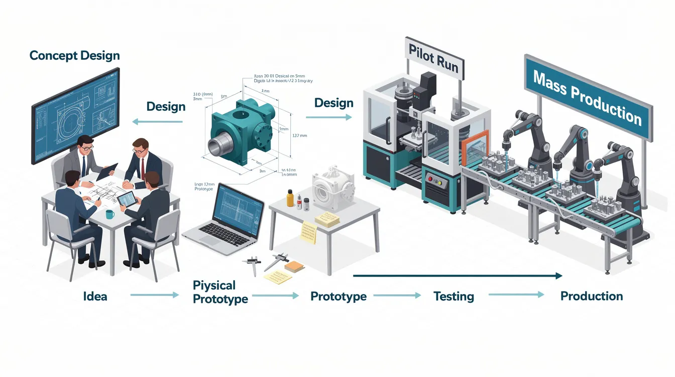
Prototyping Manufacturing: From First Concept to Final Production
Introduction to Prototyping Manufacturing
Prototyping manufacturing is the practice of building physical parts from design data to validate shape, fit, function, and manufacturability before committing to full-scale production. For OEMs and design engineers, it is a foundational step in the manufacturing process that directly determines whether a product reaches the market on time and within budget.
The backbone of modern prototype manufacturing includes processes like CNC machining, 3D printing, and injection molding-each suited to different stages of the product development process. At Anebon Metal Products Limited, we support projects from first concept models through to final production parts, providing precision CNC machining, die casting, sheet metal fabrication, and DFM consulting under one roof.
The payoff of investing in prototyping is clear: prototyping improves time-to-market by identifying flaws early in development, minimizes risks associated with launching new products, and reduces product development costs and timelines. Rather than discovering a critical interference or tolerance issue after tooling is complete, structured prototyping catches those problems when fixing them costs a fraction of what it would later.
Key Aspects of Prototype Manufacturing
In concrete terms, prototype manufacturing means creating physical samples to validate design, function, and manufacturability before mass production. Prototypes help validate ideas and assumptions early in development, giving engineering teams tangible evidence rather than relying solely on CAD renderings and simulation outputs. Physical prototypes engage stakeholders better than digital renderings, which is why even teams with sophisticated CAE tools still build parts.
Different fidelity levels serve different purposes at different stages:
-
Looks-like prototypes focus on visual appearance, proportions, and ergonomics. Materials and internal structure may differ from production intent.
-
Works-like prototypes test core technologies and functions of a product-mechanical performance, thermal behavior, sealing. Materials and processes are closer to production.
-
Pre-production prototypes are built using production tools, materials, and processes. They should be nearly indistinguishable from the final product.
The key to effective prototyping is aligning your prototype goals with the intended actual manufacturing process. If the end product will be injection molded, the prototype geometry should already include draft angles and appropriate wall thicknesses-even if the prototype itself is CNC machined. This alignment prevents a common trap where teams prototype a shape that cannot be economically molded.
Design for manufacturability feedback plays a critical role here. DFM saves time and costs during production by catching geometry issues, overly tight tolerances, and material mismatches before they become expensive tooling changes. Anebon provides structured DFM reviews as part of our prototyping services, evaluating features like internal radii, pocket depths, and tolerance appropriateness against the target production process.
Prototype Types Along the Product Development Cycle
The prototyping process follows a clear progression through the development cycle. Each stage has a distinct purpose, and feedback from one stage feeds directly into the next iteration-tightening tolerances, refining materials, and improving geometry.
|
Prototype Type |
Purpose |
Typical Methods |
|---|---|---|
|
Proof-of-Concept (PoC) |
Validate feasibility of a basic idea or mechanism |
FDM 3D printing, simple CNC, hand fabrication |
|
Concept Models |
Evaluate aesthetics, proportions, ergonomics |
SLA printing, CNC machined visual models |
|
Engineering Prototypes |
Test strength, thermal performance, tolerances, assembly |
CNC machining in production metals/plastics, SLS |
|
Pre-Production / Final Prototypes |
Mirror final production specs for regulatory and production validation |
Injection molding (bridge tooling), die casting, full CNC |
Proof-of-concept prototypes validate ideas and assumptions early. They answer “does this mechanism work?” without worrying about surface finish or exact material properties. Looks-like prototypes represent the final product at an abstract level-useful for market appeal assessments and stakeholder reviews. Works-like prototypes test core technologies and functions, while engineering prototypes are designed for manufacturing and user testing under realistic conditions.
Consider a practical example from the automotive industry. Early prototypes for an interior control panel might be 3D printed in ABS to test packaging and ergonomic fit within the dashboard. Engineering prototypes are then CNC machined in production-grade PC/ABS blends to evaluate snap-fit retention, thermal expansion, and vibration resistance. Final prototypes come from bridge injection molds so the team can validate assembly behavior, surface texture, and color matching before committing to hardened production tooling.
This iterative process is what makes prototyping an iterative design cycle for product enhancement. Multiple prototypes allow exploration of design options without costly tooling, and each round of user feedback sharpens the design before large capital is committed.
Manufacturing Technologies Used in Prototyping
No single technology fits all prototypes. Engineers routinely combine additive manufacturing and subtractive methods across a project’s lifecycle, selecting processes based on fidelity needs, material requirements, timeline, and budget. Prototyping in manufacturing has evolved from manual crafting to advanced digital methods, and today’s toolkit includes CNC machining, various additive processes, injection molding with rapid tooling, die casting, and sheet metal fabrication. Casting is also a common prototyping method for metal housings and structural components.
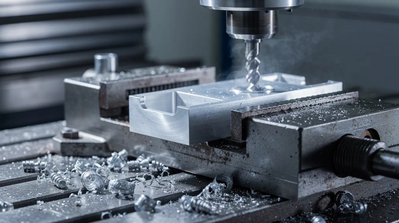
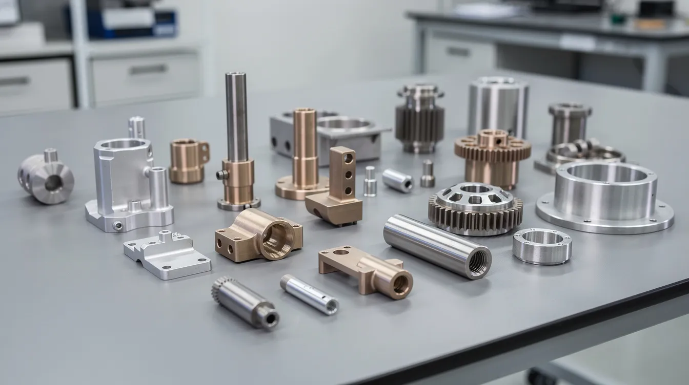
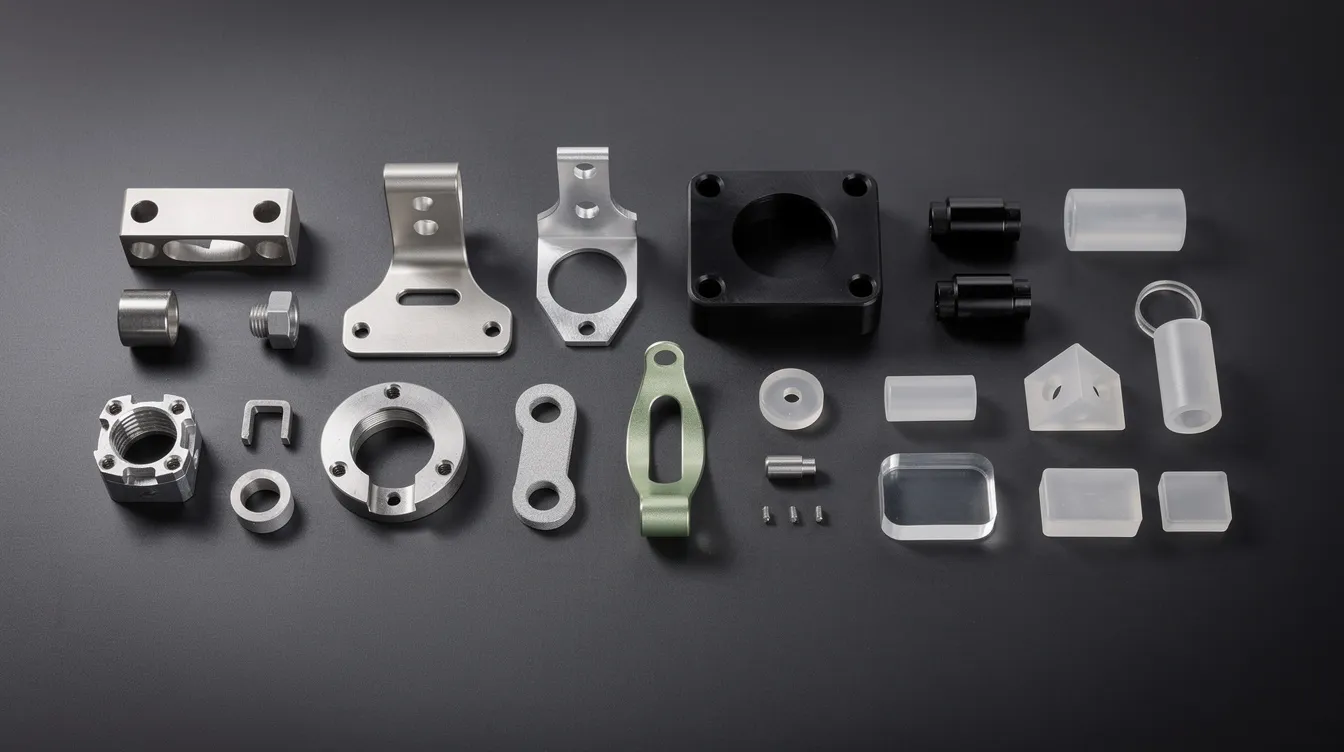
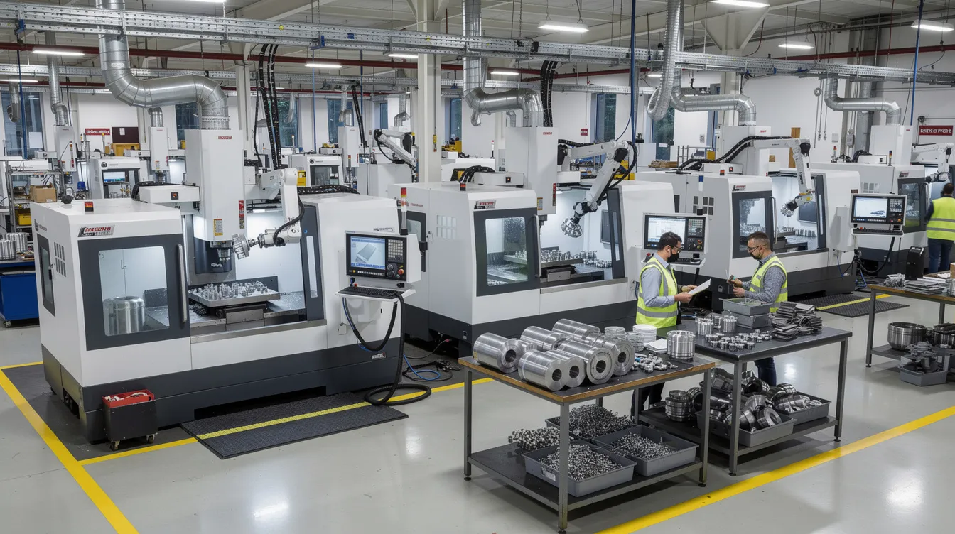
CNC Machining for Prototype Manufacturing
CNC machining is a subtractive manufacturing process that removes material from a solid block to create precise components. For prototype manufacturing, CNC milling and CNC turning are used to produce parts in production-equivalent metals and plastics-aluminum alloys (6061-T6, 7075), stainless steels (304, 316), titanium (Ti-6Al-4V), and engineering plastics like PEEK and nylon.
Where CNC prototyping excels:
-
Functional testing where strength, heat resistance, or tight tolerances are critical
-
Medical device and aerospace parts requiring biocompatible or high-performance materials
-
Situations where the prototype material must match the production grade for valid test data
Standard CNC prototype tolerances sit around ±0.13 mm (±0.005 in), with precision features held to ±0.025–0.05 mm. At Anebon, our high-precision capabilities reach ±0.002 mm for critical features like bearing seats, sealing surfaces, and optical alignments. Surface finishes of Ra 1.6–3.2 µm are achievable on aluminum prototypes without secondary polishing.
5-axis machining handles complex geometries and undercuts that simulate final production features more accurately, reducing the gap between prototype and production part behavior. A common path: customers start with CNC prototypes to validate fit and function, then transition to die casting or injection molding for volume production once the design stabilizes.
3D Printing and Additive Manufacturing
3D printing is an additive manufacturing process that builds parts layer-by-layer from a CAD model, and it is largely synonymous with rapid prototyping. It enables quick iterations for design validation and allows teams to create prototypes overnight that would take days via conventional methods.
The most common processes include:
-
Fused deposition modeling (FDM): The most widely used 3D printing method. Cost effective for quick functional checks and early prototypes, though surface finish is coarse and mechanical properties are limited.
-
Stereolithography (SLA): Offers the highest resolution among 3D printing technologies, producing fine details and smooth surfaces ideal for detailed visual models and concept models.
-
Selective laser sintering (SLS): Produces strong, functional prototypes in engineering grade thermoplastics like nylon, suitable for usability testing and mechanical evaluation.
-
Direct metal laser sintering (DMLS): Builds metal parts for situations requiring complex internal channels, lattice structures, or weight-optimized designs that cannot be machined conventionally.
Additive manufacturing helps explore complex geometries-internal cooling channels, organic structures, lattice infill-that would be impossible or prohibitively expensive with subtractive methods. Rapid prototyping allows for greater product customization, letting teams test multiple design variants in parallel.
However, additive processes have clear limitations. Anisotropic strength means printed parts behave differently depending on build orientation. Layer lines affect surface finish. Material characteristics often differ from injection molded or machined equivalents. When a project requires production-representative mechanical properties, validated sealing performance, or cosmetic surfaces, it is time to transition from 3D printing to CNC machining or injection molding.
Injection Molding and Rapid Tooling
Injection molding is the go-to manufacturing process for high-volume plastic parts once designs stabilize. But it also plays a critical role during late-stage prototyping through rapid tooling and bridge tooling.
Rapid tooling uses aluminum or soft-steel molds with fewer cavities and simplified tool bases. These prototype tools can be completed in 1–4 weeks, compared to 6–12+ weeks for hardened production tools. Tool life ranges from 1,000 to 50,000 shots depending on material and geometry-sufficient for engineering validation, pilot builds, and early market testing.
The injection molded parts produced from bridge tooling allow accurate functional testing of:
-
Snap-fits, living hinges, and clip retention
-
Assembly behavior with mating components
-
Surface texture, color matching, and cosmetic appearance
-
Material behavior under thermal cycling and chemical exposure
This approach is specifically relevant for consumer electronics housings, automotive interior components, and medical device enclosures where the difference between a CNC-machined prototype and a molded part-gate marks, weld lines, shrinkage patterns-directly affects validation accuracy.
Material Selection and Design Considerations
Material selection in prototypes must reflect both immediate testing needs and eventual production constraints. Choosing a prototype material close to the final production grade improves the accuracy of functional testing and life testing results. Prototyping allows for final testing and validation using intended materials, which is why production-equivalent material choices matter.
Common metals used at Anebon:
|
Material |
Key Properties |
Typical Applications |
|---|---|---|
|
6061-T6 Aluminum |
Lightweight, machinable, good strength |
Structural frames, housings, brackets |
|
7075 Aluminum |
High strength-to-weight ratio |
Aerospace, high-load components |
|
304/316 Stainless Steel |
Corrosion resistance, durability |
Medical instruments, food-contact parts |
|
Ti-6Al-4V Titanium |
Biocompatible, high strength, heat resistant |
Implants, aerospace, high-temp applications |
Common plastics: ABS, polycarbonate (PC), PEEK, nylon, PC/ABS blends, and liquid silicone rubber for overmolded or flexible components.
Key design considerations that affect both prototype accuracy and production feasibility:
-
Wall thickness: Consistent walls prevent warping in molded parts and reduce machining time in CNC prototypes
-
Draft angles: Required for injection molded or die-cast parts to release from tooling; should be incorporated even in CNC prototype geometry
-
Tolerances: Critical features get tight tolerances; non-critical features stay looser to reduce costs. Standards like ISO 2768 or GD&T provide a structured framework
-
Anisotropy: 3D printed and SLS parts exhibit directional strength differences that must be accounted for when interpreting test results
Detecting and Resolving Design Flaws Early
Physical prototypes reveal design flaws not visible in CAD-interference between mating parts, assembly difficulty, ergonomic issues, and tolerance stack-up problems. Prototyping helps identify design flaws before mass production, when fixing them is orders of magnitude cheaper.
Consider a common scenario: a consumer electronics enclosure has a mounting boss designed to accept a self-tapping screw. In CAD, the boss clears surrounding features with adequate margin. During trial assembly of the first physical prototype, an engineer discovers that the boss interferes with a cable routing channel when the PCB is installed at a slight angle-something that was invisible in the 3D model because the cable was modeled as a rigid body.
This kind of discovery is exactly why prototyping minimizes design errors and risks in product development. Iterative prototyping with small design adjustments-moving the boss 2 mm, adding a cable guide rib-resolves the issue before any injection mold steel is cut.
Anebon’s DFM review process serves as a structured feedback loop. Our engineers evaluate geometry (access, pockets, thin walls), specification (tolerance appropriateness, finish requirements), material choices, and process context. This approach supports cost efficiency by reducing redesigns and recalls downstream.
Functional Testing, Validation, and Certification
Prototypes serve a purpose beyond visual confirmation. Functional prototypes evaluate how a part performs under stress, thermal loads, vibration, and environmental exposure. Prototypes facilitate direct user testing and feedback, and iterative testing improves product reliability before market launch.
Engineering validation typically follows structured phases:
-
EVT (Engineering Validation Testing): First-round functional testing on engineering prototypes. Checks mechanical performance, thermal behavior, sealing.
-
DVT (Design Validation Testing): Testing with production-intent processes and materials. Includes environmental exposure (humidity, UV, temperature cycling), load testing, and safety evaluations.
-
PVT (Pilot Validation Testing): Pre-production units tested for assembly line compatibility, quality control consistency, and regulatory compliance.
Specific tests vary by industry. Automotive components face NVH (noise, vibration, harshness) and crash simulations. Medical devices undergo sterilization cycling and biocompatibility evaluation. Aerospace parts require certification-grade documentation of every material lot and dimensional inspection.
Using production-equivalent processes-CNC machining, die casting, injection molding-increases the relevance of functional testing results. A 3D-printed housing cannot replicate the weld lines, gate vestiges, or crystallinity of a molded part, and those differences affect mechanical properties and long-term durability.
From Concept Models to Production-Ready Units
There is a meaningful difference between low-fidelity concept models built for appearance and basic ergonomics and high-fidelity, production-intent prototypes that must match the final product in every measurable way.
Early prototypes are typically 3D printed or loosely machined-fast, inexpensive, and disposable. As designs converge through multiple iterations and user feedback, the prototyping process shifts to CNC machined or injection molded parts with tighter dimensional control and production-grade materials. This progression turns innovative ideas into production quality parts.
Anebon helps customers navigate this shift. Our rapid prototyping services cover early-stage concept pieces machined in days, and our production capabilities extend to tightly controlled pre-production parts with full inspection documentation. Prototyping enhances communication and collaboration among stakeholders because each successive physical prototype gives everyone-engineering, procurement, quality, and the end customer-a shared reference point.
Documenting test results and design changes at each stage is critical for traceability. Industries with regulatory requirements-medical devices, aerospace, automotive-require this documentation for certification submissions. Prototyping enables tangible testing of product ideas before investment in production tooling, and the records generated during prototyping become part of the product’s quality file.
Transitioning from Prototype to Mass Production
The transition from prototype manufacturing to mass production is a critical, high-impact stage where design decisions meet production economics. Transitioning to production requires optimizing processes and materials, and missteps here-selecting the wrong process, under-specifying tolerances, or skipping pilot validation-create delays and cost overruns.
Key steps in the transition:
-
DFM optimization: Finalize geometry for the chosen production process. Simplify features, reduce undercuts, standardize where possible.
-
Process selection: Decide between injection molding, die casting, sheet metal fabrication, or continued CNC machining based on volume, cost, and performance needs.
-
Tooling design and build: Commission production molds, dies, or fixtures. Hardened steel tools for injection molding support 100,000–500,000+ shots.
-
Pilot runs: Small-batch production (hundreds to low thousands) to validate the production process, assembly line, and quality controls.
-
First Article Inspection (FAI): Measure all critical tolerances, document results, and approve before scale production begins.
Anebon offers a continuous path through this transition: from rapid prototyping through process refinement to stable volume manufacturing. Our quality management systems-ISO 9001:2015 and ISO 14001:2015 certifications-provide the framework that overseas OEMs require for compliance and supply chain confidence. Prototyping aids in evaluating manufacturing processes before production, so the ramp-up to mass production carries less risk.
Cost, Lead Time, and Process Optimization
Every decision made during the design process and prototyping phase has downstream cost implications. Over-complex features increase tooling price and cycle time. Unnecessarily tight tolerances across all features-rather than only on critical datums-can double machining cost without functional benefit. Rapid prototyping reduces product development time significantly and allows for cost-effective testing of design concepts before expensive commitments.
When to move from CNC prototypes to dedicated tooling:
-
If projected volume exceeds 500–1,000 units, injection molding or die casting typically becomes more cost effective than per-part CNC machining
-
If part geometry requires features only achievable through molding (e.g., internal snap-fits, thin-wall sections under 1 mm)
-
If low volume production needs can be met with rapid tooling before investing in hardened steel tools
Early process simulations-mold flow analysis, finite element analysis, tolerance stack-up studies-reduce scrap rates and rework during ramp-up. These virtual tools cut down trial rounds from three or four to one or two, saving weeks of lead times and tens of thousands of dollars in tool corrections.
Anebon’s experience with overseas OEMs means we understand that competitive pricing and predictable delivery matter as much as precision. Early quoting, transparent lead time breakdowns, and proactive communication keep projects on schedule. A typical injection mold project-from RFQ through mold design, steel procurement, machining, trials, and first article-runs 8–16 weeks depending on complexity. Planning for this timeline from the start prevents last-minute pressure that compromises quality.
Industries, Use Cases, and Anebon’s Capabilities
Prototyping manufacturing serves every sector of the manufacturing industry where custom parts require validation before volume commitment. Rapid prototyping accelerates design iteration and testing processes across all of them, helping teams get to market faster with fewer surprises.
Industries we serve:
-
Aerospace: Tight tolerances, lightweight metals, complex structures, certification-grade documentation
-
Medical Devices: Biocompatible materials, sterilization compatibility, regulatory traceability
-
Automotive: Structural components, interior plastics, functional testing under vibration and thermal loads
-
Robotics & Industrial Machinery: Precise metal parts, long service life, heat and load resistance
-
Consumer electronics: High-volume plastic housings, small precision metal components, overmolded assemblies
Application examples:
-
Aluminum drone frames: CNC machined from 7075 aluminum to test structural rigidity and vibration modes during flight testing; later transitioned to die casting for production volumes
-
Surgical instruments: Early 3D printed prototypes for ergonomic evaluation with surgeons; final versions CNC machined in 316L stainless steel, polished and passivated to medical standards
-
Electronic enclosures: Bridge injection molds used for pilot programs and carrier approval testing; production molds in hardened P20 steel for 500K+ unit runs
Anebon’s core manufacturing capabilities:
-
Precision CNC prototype machining (milling, turning, 5-axis) with tolerances to ±0.002 mm
-
Die casting for aluminum and zinc alloy housings and structural parts
-
Sheet metal fabrication including laser cutting, bending, and welding
-
Additive-compatible DFM consulting for teams using 3D printing in early stages
-
Surface treatments: anodizing, plating, powder coating, polishing, passivation
-
Industry certifications: ISO 9001:2015 and ISO 14001:2015
Rapid prototyping enhances collaboration through digital models and physical samples, making it easier for distributed teams-your engineers in one country, our manufacturing partners in another-to stay aligned on specifications and expectations. Rapid prototyping companies and prototyping services providers vary widely in capability; what sets Anebon apart is the ability to deliver consistent results from a single prototype through pilot builds to stable production, without compromising quality at any stage.
Whether you need durable prototypes for environmental testing, produce parts for a pilot program, or scale production to tens of thousands of units, our specialized services cover the full product development cycle. We work with teams at the early stage of a design process through final production, ensuring that each development cycle moves the project closer to a validated, manufacturable product.
Ready to move your project forward? Request a quote or share your CAD model files with our engineering team for a feasibility assessment and DFM feedback. We respond within 24 hours with preliminary guidance on process selection, material recommendations, and realistic timelines for your custom parts.