Essential Guide to Pin Molding: Techniques and Tips for Success
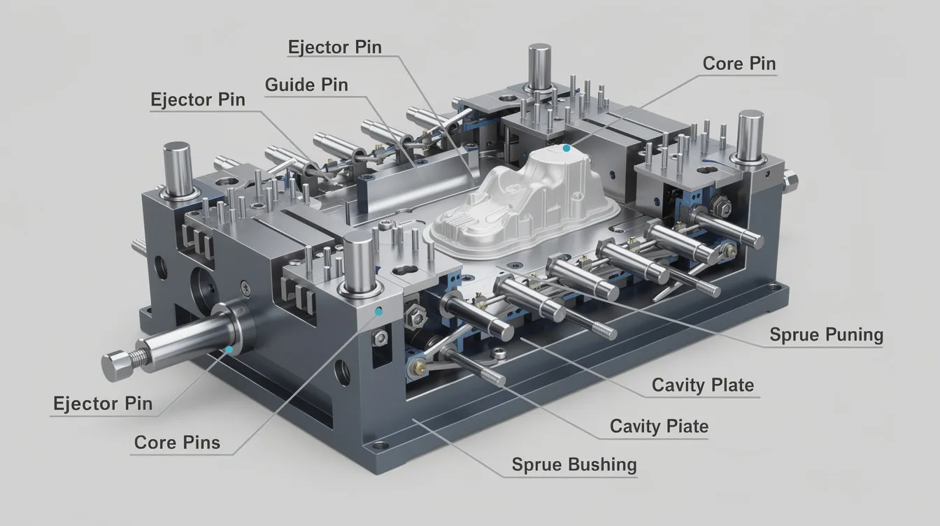
Pin Molding: Ejector Pins, Core Pins, and Critical Mold Components
Introduction to Pin Molding in Injection Molding
Pin molding refers to the design and use of specialized metal pins-ejector pins, core pins, ejector sleeves, and related mold components-to form internal features, eject finished parts, and control surface quality in the injection molding process and in die casting. Pin molding is foundational for mass-producing precise, detailed components across industries. The automotive industry relies on pin molding for durable inner components, electronics manufacturing uses pin molding for plastic casings and connectors, and medical devices require extreme precision and often use pin molding. Pin molding is also used to produce common consumer goods like toys and containers, and is crucial for creating complex components for aerospace applications.
Pin design directly affects molded parts quality, visible ejector pin marks, cycle times, and mold life. Black ejector pins, core pins, and ejector sleeves each solve different problems-from forming screw bosses in automotive connectors to creating tiny through-holes in medical housings. Anebon Metal Products Limited, an ISO 9001:2015 and ISO 14001:2015 certified precision manufacturer in Dongguan, China, supplies custom mold components and finished molded parts to overseas OEMs, with tolerances as tight as ±0.002 mm.
What you will learn:
-
Core concepts and terminology behind pin molding
-
Pin types, materials, and surface treatments
-
Design guidelines for ejector pin placement and sizing
-
How to manage ejector pin marks and prevent pin failures
-
Differences across plastics, liquid silicone rubber, and die casting
What Is Pin Molding? Core Concepts and Terminology
Pin molding informally covers all that goes into selecting, placing, and treating pins inside injection molds. Injection molding relies on custom-machined steel or aluminum molds split into an A-side (the cavity that defines external geometry) and a b side mold half (the core side housing ejector systems). Pin molding uses specialized metal pins to create internal shapes, while injection molding produces components with minimal waste and high material versatility.
-
Ejector pins push molded parts out of the mold once cooled plastic has solidified. They are located in the b side of the mold, secured in the ejector plate, and pins extend through bores to contact the part surface when the mold opens.
-
Core pins are fixed or semi-fixed pins that displace material during injection. Mold core pins create voids or intricate shapes within molded parts-holes, slots, and threads.
-
Ejector sleeves are hollow sleeves that slide around a core pin to distribute part ejection force evenly around bosses.
-
Return pins facilitate mold reset after part ejection, ensure precise alignment of mold halves, and enhance cycle efficiency by reducing downtime. High-quality return pins improve productivity in injection molding and must endure thousands of cycles in high-pressure environments.
-
Leader pins guide the two mold halves together during closing, maintaining alignment perpendicular to the parting line.
Ejector pins minimize manual handling during the demolding cycle. In a 4-cavity mold for ABS electronic housings, for example, each cavity may use 6–10 ejector pins on interior walls plus ejector sleeves around screw bosses, with core pins forming internal mounting holes.
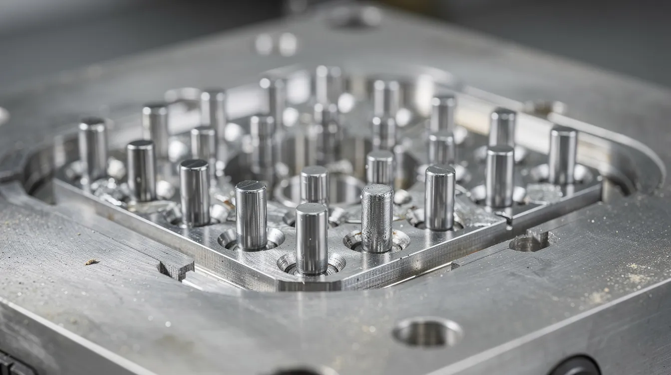
Types of Pins Used in Injection Molding
Different pin type selections depend on resin choice, temperature, part geometry, and production volume. Core pins and ejector pins are essential for precision and efficiency in manufacturing; choosing the right shape and diameter for each feature determines whether parts eject cleanly.
Standard ejector pins are straight, solid rods-common pin diameter ranges from 1.5 mm to 25 mm (roughly 1/16 inch to 1 inch). Typical hardness values sit at 58–62 HRC per DIN 1530. In most cases, ejector pins push cooled plastic off the core using a flat face.
Core pins form internal features. Core pins can be straight, tapered, or have replaceable tips, depending on the hole geometry. A contoured pin variant may be used when the internal shape is non-cylindrical. Insert molding binds metal pins to plastic by placing them in the mold cavity before injection, creating a mechanical bond.
Ejector sleeves surround a core pin and distribute force around a boss, reducing the likelihood of deformation. Ejector pads and ejector blocks serve a similar role for large, flat plastic area sections, providing enough surface area to prevent puncturing thin walls. Blade-style pins handle thin ribs and rib edges where round pins won’t fit.
Materials and Surface Treatments for Ejector Pins and Core Pins
Material choice controls wear, corrosion resistance, hardness, and the risk of pin breakage across millions of cycles.
H13 / SKD61 tool steel is the workhorse-heat-treated to HRC 48–52 for through-hard applications. Through-hard ejector pins maintain consistent hardness throughout their diameter, making them suitable for standard molding process temperatures below about 200 °C. High speed steel variants offer additional toughness for the longest pins with high aspect ratios.
Nitride H13 ejector pins feature a surface layer of HRC 65–70 over a softer, tougher core. Nitride H13 ejector pins withstand temperatures up to 600 °C, making them ideal for engineering resins and aluminum die casting tools where thermal cycling is severe.
Black ejector pins-coated with DLC or PVD-can endure temperatures up to 1000 °C. They reduce friction and galling in multi-cavity molds running abrasive glass-filled resins. Anebon recommends them for high-volume tooling but not for soft elastomers where coatings may degrade.
For corrosive resins (PVC, flame-retardant grades) or humid environments, stainless tool steels (420, 440C) provide corrosion resistance. Anebon helps customers balance cost and durability when selecting pin materials.
Design Guidelines for Ejector Pins in Pin Molding
Poor ejector pin placement causes 70% of mold wear issues and leads to sticking parts, pin breaks, and cosmetic defects. Getting placement right early addresses major part design concerns.
Ejector pins need a flat surface to push against. Place them on the heaviest wall sections, away from critical areas and cosmetic surfaces, and mirror part geometry to spread more force evenly. Several factors affect pin placement-wall thickness, draft angle, and proximity to ribs or other mold components. On a 150 × 100 mm panel, 8–12 pins of 4–6 mm diameter spaced every 20–30 mm is a practical starting point.
-
Do: Use enough surface area per pin; distribute pins symmetrically; specify clearance of 0.01–0.02 mm for resins like PP and nylon, up to 0.03 mm for PC/ABS.
-
Avoid: Placing pins on gloss surfaces; using high-aspect-ratio pins without stepped shoulders; ignoring pin movement stroke limits.
Softer resins may require wider ejector pins to prevent damage, and stickier resins need more pins or ejector sleeves. Ejector pins can reduce cycle times by 15% on average by enabling faster, automated part ejection-high-efficiency injection molding can produce a part in seconds once tooling is built. Ejector pins apply consistent force, improving product quality and overall efficiency. In the injection molding world, a pad or wider-face pin is often preferred on thin walls to minimize stress.
For liquid silicone rubber molds, conventional ejector pins are rarely used. LSR parts are very elastic and typically manually pulled from the mold or released with vacuum and peeling systems, since pin contact would leave marks or tears.
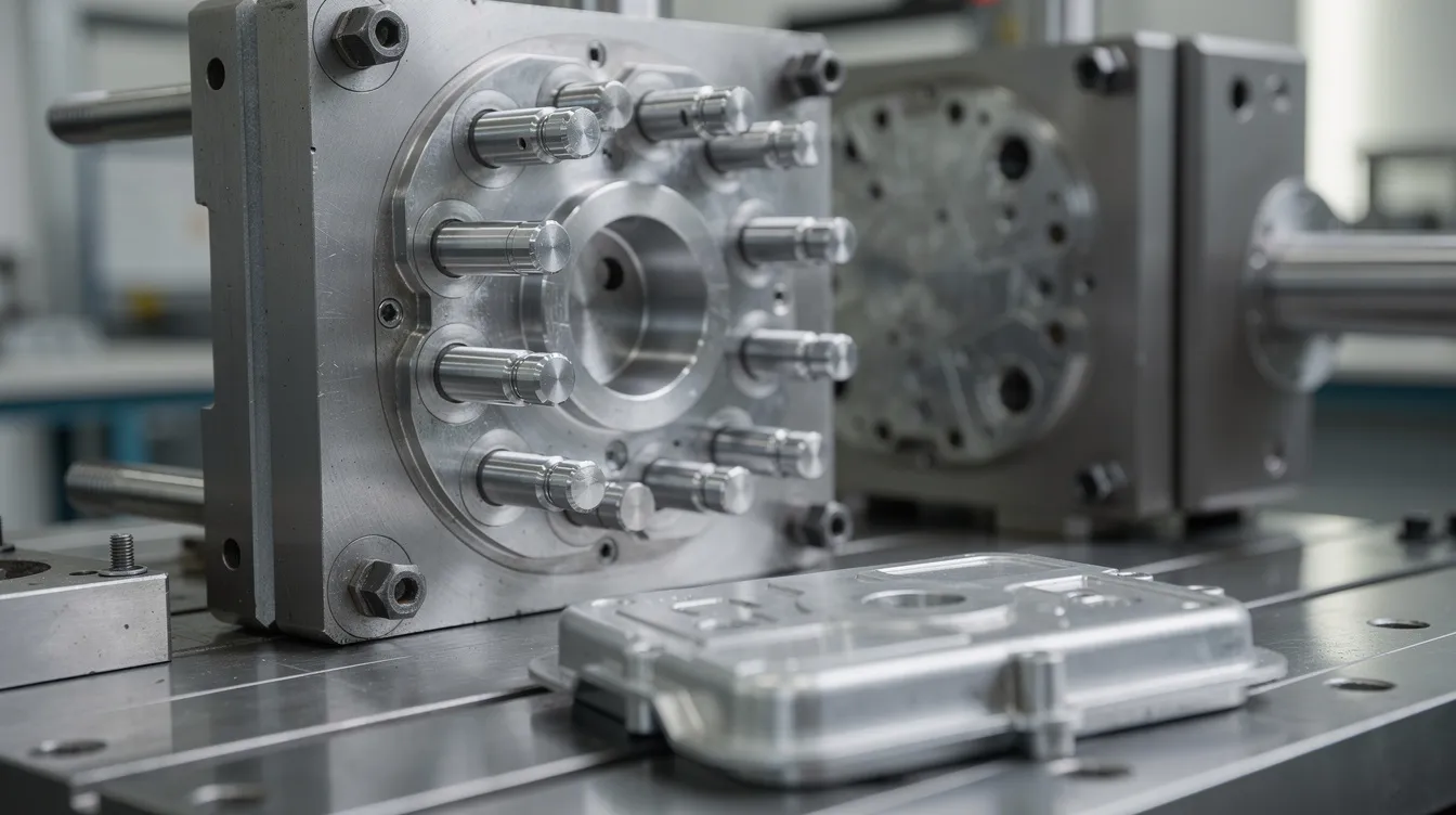
Managing Ejector Pin Marks and Surface Quality
Ejector pins can leave marks on molded parts during ejection-small witness circles or depressions on the part surface. Ejector pin marks can lead to cosmetic defects or cracks, especially on Class-A automotive or consumer electronics surfaces.
Pin face shape matters: flat faces maximize contact but leave sharper outlines; a slightly domed pad distributes force and reduces mark depth. Polished tips (Ra < 0.2 µm) produce a smooth surface with less visible marking. On a gloss PC automotive bezel, relocating 3 mm flat pins from the visible face to structural ribs at the rear-and switching to 6 mm radiused, PVD-coated pins-reduced cosmetic reject rates dramatically. Ejector pins are crucial for efficient part removal in molding, but reducing cycle times and marks requires thoughtful design.
Common Pin Failures and How to Prevent Them
Main failure modes include pin bending, breakage, galling in the bore, and corrosion. Mechanical causes: undersized diameter, too few pins to eject the part without excessive force, or misalignment between the ejector plate and guide pillars. When the machine applies ejection force through a warped plate, pins bind.
Thermal causes include running engineering resins or die casting alloys beyond a pin’s rated temperature, softening the steel.
Remedies: increase pin count, switch to nitrided or black ejector pins, add lubrication, and improve venting. Track failure data-resin, cycle count, pin location-to refine future designs. Pin molding provides exceptional strength through a mechanical bond with molten plastic, but only when pins survive millions of cycles.
Pin Molding with Different Materials: Plastics, LSR, and Die Casting
Standard thermoplastic injection molding runs at 60–120 MPa and 200–320 °C melt temperatures. Pin molding produces high-precision components across manufacturing sectors under these conditions, and automotive pin molding produces specialized fasteners and connectors in glass-filled nylons.
LSR molding avoids ejector pins almost entirely. Parts are elastic enough to be peeled or manually pulled from the mold, and Anebon designs LSR tooling to accommodate draft-based demolding.
Die casting subjects pins to molten aluminum at ~650–700 °C. Nitrided H13 or coated pins with internal cooling are essential. Precise medical components may require sub-2 mm core pin diameters with concentricity below 0.005 mm.
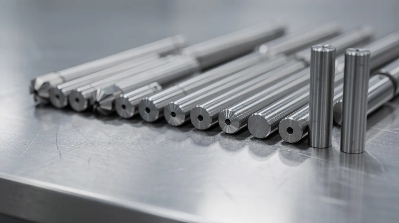
How Anebon Supports Precision Pin Molding Projects
Anebon Metal Products Limited machines ejector pins, core pins, and complex mold inserts using CNC machining and 5-axis CNC machining, holding pin diameters to ±0.002 mm. This precision improves ejection consistency and extends mold life.
Anebon supplies H13, stainless tool steels, DLC-coated black ejector pins, and matched ejector sleeves for multi-cavity tools. Engineering support includes DFM feedback on pin placement, resin-specific recommendations, and layout optimization during quotation. OEMs, design engineers, and R&D teams can share 3D models (STEP, IGES, native CAD) for a fast, no-obligation review. Since 2010, Anebon has helped overseas clients reduce costly tooling changes by getting pin design right before cutting steel.
Conclusion: Designing Better Pin Molding Systems for Reliable Production
Correct selection and design of ejector pins, core pins, and other mold components is the difference between a mold that runs trouble-free for a million cycles and one that causes constant downtime. Minimizing ejector pin marks, preventing failures, and matching materials to the molding process-whether plastic, LSR, or die casting-protects both part quality and production budgets.
Involve your manufacturing partner early. Contact Anebon for technical guidance, DFM support, and precision manufacturing of custom pins, molds, and molded parts-and turn pin molding from a design concern into a competitive advantage.