Essential Guide to Metal Shrinking Techniques for Precision Work
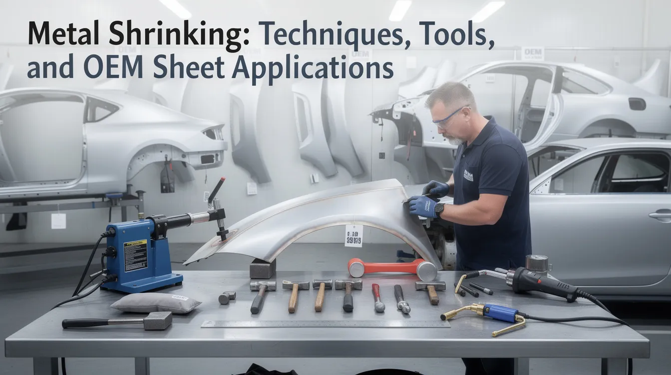
Metal Shrinking: Techniques, Tools, and OEM Sheet Metal Applications
Metal shrinking is one of the most overlooked yet critical skills in precision sheet metal fabrication. Whether you are restoring a classic car hood, producing aerospace skins, or manufacturing appliance panels at volume, knowing how to shrink metal properly can mean the difference between a cosmetically flawless part and an expensive reject. This guide covers the core techniques, the tools every fabricator should have in their tool box, and how modern OEM workflows minimize the need for manual correction.
What Is Metal Shrinking and Why It Matters in Sheet Metal Fabrication
Metal shrinking is the controlled reduction of surface area in a sheet metal panel. The process compresses and gathers metal fibers (the crystalline grains within the material) to remove excess area where the panel has been stretched, distorted, or over-formed. The result is a tighter, more accurate shape that meets design intent.
The distinction between stretching and shrinking is straightforward. Stretching pulls grains apart, making the panel larger or flatter. Shrinking pushes them together, reducing area and restoring contour. Think of it this way: if a panel has been stretched in one spot-say by a dent repair or a deep draw-that area now has more material than its neighbors. To fix it, you need to shrink that zone back into alignment with the surrounding metal.
Common use cases include:
-
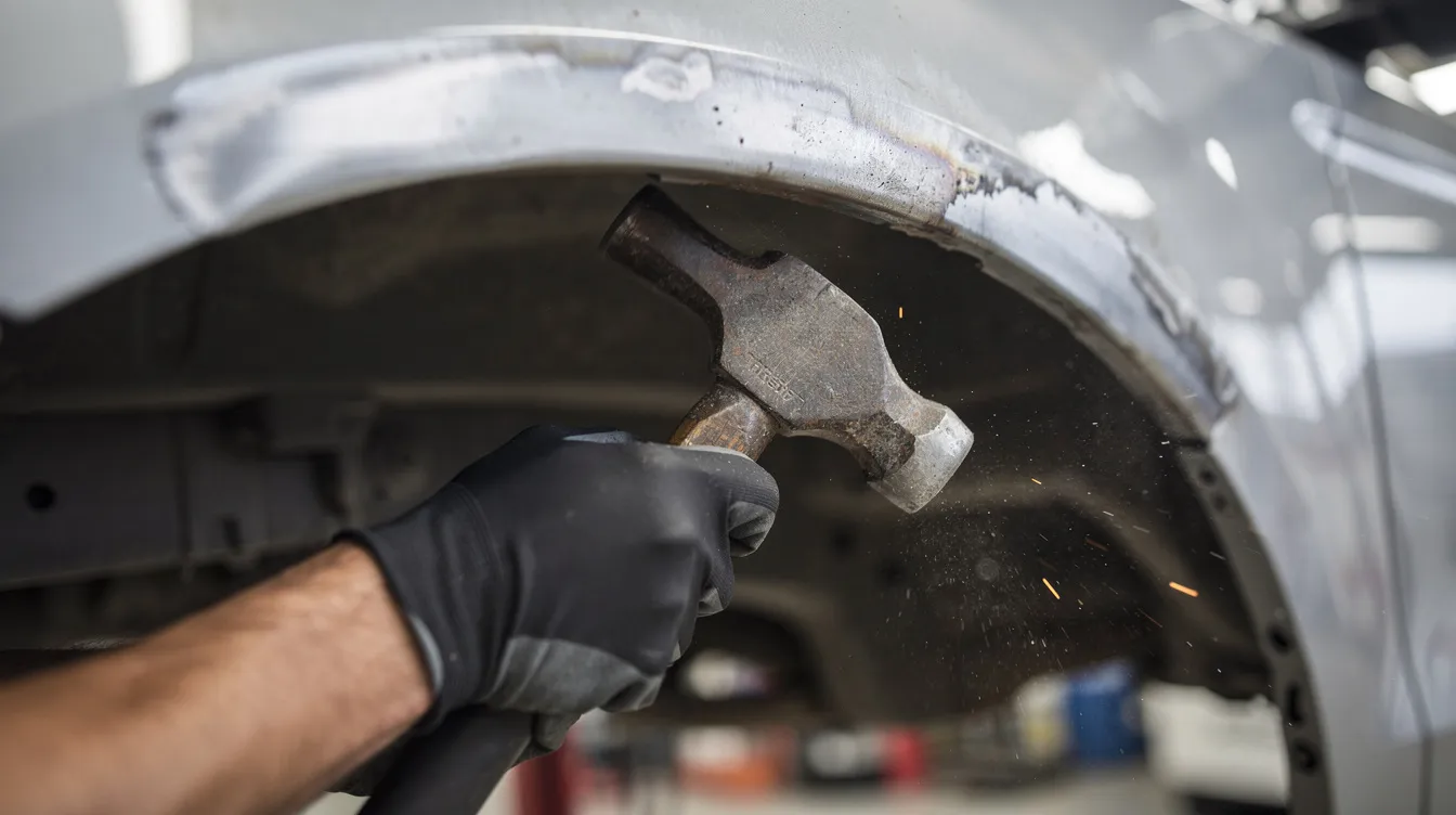
Automotive body repair and restoration – metal shrinking is used in automotive restoration to fix warping and oil canning on hoods, doors, and roof panels.
-
Aerospace skins – shrinking is essential in creating smooth curves and structural components in aerospace, where aerodynamic surfaces must be precise.
-
Appliance panels and precision enclosures – elevator interiors, machine guards, and electronics housings all demand flat, stable surfaces.
Shrinking is basically a foundational skill in forming and repairing complex metal pieces. The typical materials involved are low-carbon steel (0.9–1.2 mm thickness), aluminum alloys in the 5xxx and 6xxx series, and stainless steels-all commonly used in OEM sheet metal parts.
At Anebon Metal Products Limited, we handle these materials daily as an ISO-certified precision sheet metal and CNC machining supplier serving overseas OEMs across automotive, aerospace, electronics, and industrial sectors.
Common Causes of Panel Distortion and “Oil Canning”
Before selecting a shrinking process, you need to understand what created the distortion in the first place. Different root causes call for different correction methods.
Oil canning refers to the unstable waviness in large, flat sheet metal panels-areas that “pop” in and out under light pressure or shift visibly under changing lighting. It is one of the most common cosmetic defects in fabricated panels, and it signals that the panel lacks stiffness or carries residual stress.
Typical causes include:
-
Welding heat input – fusion welding introduces localized expansion followed by constrained contraction during cooling. The weld zone develops tensile residual stress while surrounding areas go into compression. In aluminum, the heat-affected zone can lose 30–50% of its yield strength.
-
Over-stretching during forming – deep drawing, stretching flanges, or aggressive metal shaping can exceed the elastic limit, leaving permanent deformation.
-
Residual stress from rolling or stamping – coil stock carries directional stresses from the mill. Research on 7050-T7451 aluminum plate showed that inherent residual stress fields alone can distort high-aspect-ratio parts beyond aerospace tolerances even before machining.
-
Improper bracing and fixturing – panels processed without strongbacks, copper backing bars for heat sinks, or adequate clamps will warp freely.
Consider a practical example: a 1.0 mm steel hood develops visible oil canning around a patch panel weld because the heat input was not balanced. The fix requires cold or hot shrinking-or both-to flatten the warped sheet metal before the part moves to paint.
For OEMs in automotive and appliances, distortion impacts cosmetic appearance (visible waviness ruins paint finish), NVH behavior (gaps and misalignment cause squeaks), and assembly alignment (doors and hood lines must lay flush).
Cold Shrinking Techniques for Sheet Metal
Cold shrinking methods avoid local heating entirely, relying on mechanical force to compress material. They are the go-to choice for thinner panels and precision work where preserving the alloy’s temper matters.
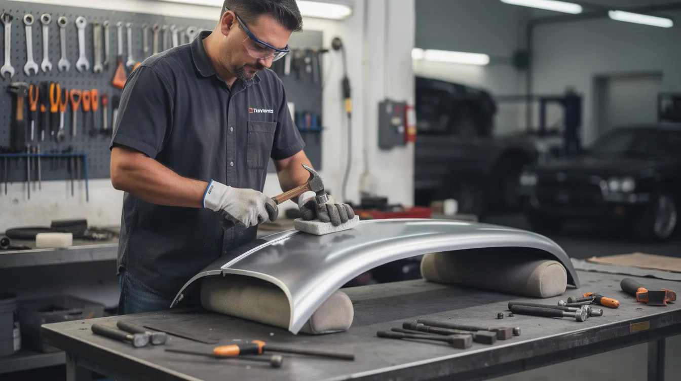
Hammer and Dolly Shrinking
The hammer and dolly method is the oldest and still one of the most effective ways to shrink metal by hand. The technique uses controlled off-dolly blows: the dolly supports the back side of the panel while shrinking hammers strike nearby-not directly over the dolly-to gather material and flatten a high spot. Hammer head shapes (spherical face, cross-pein) and dolly profiles (curved, flat, heel) are matched to the panel’s contour. This method works well on 0.8–1.5 mm steel or aluminum and can correct a dent or a subtle wave with precision.
Tuck Shrinking
Tuck shrinking shapes sheet metal panels effectively, especially along edges and flanges. A tucking fork-such as a Picard Tucking Fork, which is used for creating folds in metal-allows the fabricator to fold one edge of the material and hammer it into a small tuck. The Picard Tucking Fork is used for tucking sheet metal on window surrounds, wheel arches, and other complex profiles. The limitation is access: tuck shrinking works only on reachable edges, not the center of a large flat panel.
Mechanical Shrinker-Stretcher Machines
Cold shrinking also reduces surface area using machines like shrinking jaws or tucking forks. Mechanical shrinkers bite into metal to compress and gather the material, producing repeatable results on flanges and window openings in 0.8–2.0 mm aluminum and steel sheet. These machines are fast and consistent, and shrinking tools help correct warpage in sheet metal at production speed.
Advantages: Low risk of overheating, no change to metallurgy, repeatable results, suitable for precision work. Limitations: Slower throughput on large distortions, limited to accessible edges and small areas, and requires practice panels to develop operator skill.
Shrinking tools are essential for auto body repair-keep a selection of hammers, dollies, and a tucking fork in your shop at all times.
Hot Shrinking Process With Torch and Quench
When distortion from welding or heavy forming is too severe for cold methods alone, hot shrinking-also called torch shrinking-steps in. This method is common in body shops to remove warping after welding, and distorted metal can be corrected through heat shrinking after welding on mild steel panels.
Step-by-Step Process
-
Identify the high spot – use a straightedge or lay a flexible ruler across the panel. Mark peaks with a marker.
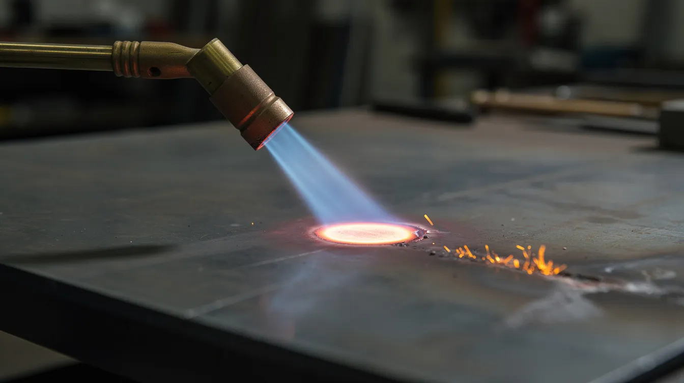
-
Heat locally – heat shrinking involves heating metal to a dull cherry red (approximately 600–700 °C for mild steel) with an oxy-acetylene torch. A propane torch can work on very thin stock, but oxy-acetylene gives better control. Basically, heat is applied to shrink metal effectively by softening the raised zone.
-
Hammer gently – using a shrinking hammer or cross-pein, work from the heated zone outward. Do not strike the center of the hot area directly. This compresses the softened fibers inward. Heat shrinking compresses the metal molecules together to increase thickness in the treated zone.
-
Quench immediately – grab a wet rag or damp rag and press it onto the heated spot. Rapid cooling causes the metal to contract, pulling the surrounding cooler material inward. You can also use cold water or compressed air to quench. The key is rapid cooling-without it, the process stalls.
-
Repeat and check – after each cycle, measure with a straightedge. Work in small areas to avoid introducing new waves.
Heat shrinking is effective for tightening warped areas of metal, but it carries risks. Applying too much heat can burn through thin panels below 0.8 mm thickness. Heat shrinking can lead to brittleness if not quenched properly after heating-always quench immediately and never let the panel air-cool slowly, as that can alter the grain structure. Using a torch on heat-treatable aluminum alloys (2xxx, 7xxx) is a bad idea because the thermal cycle destroys the temper.
Good advice: protect yourself with fire-resistant clothing, keep a rag and cold water at arm’s reach, and never leave a lit torch unattended.
Heat shrinking requires heating and rapid cooling of metal-this thermal cycle is what makes it work, but it also limits the method to low-carbon steel and non-critical alloy applications.
|
Factor |
Cold Shrinking |
Hot Shrinking |
|---|---|---|
|
Heat risk |
None |
High-flame control required |
|
Best for |
Thin panels, edges, precision work |
Severe distortions, weld repair |
|
Material limits |
Most alloys |
Mild steel only (avoid heat-treated Al) |
|
Skill level |
Moderate |
High |
|
Speed |
Slower per cycle |
Faster per cycle |
Using a Shrinking Disc on Sheet Metal Panels
A shrinking disc is a stainless steel disc-typically a Shrinking Disc is 4 ½ inches in diameter-mounted on a standard angle grinder. It has become a favorite tool for metal finishing and precision surface correction because it bridges the gap between torch shrinking and hand work.
How It Works
A shrinking disc creates localized heat through friction for shrinking metal. Because the disc only contacts the highest points on the panel surface, it selectively heats those spots. The surrounding metal stays cool, acting as a natural clamp.
Workflow
-
Coat the panel with layout dye or marker ink. Use a sanding block across the surface to reveal highs and lows-marker wipes off raised areas, stays in low spots.
-
Run the disc lightly over marked high spots at 1,500–3,000 RPM for steel (1,000–2,200 RPM for aluminum with a phenolic disc). The friction heats the peak until the metal turns blue at the contact point.
-
Quench with a damp rag, compressed air, or cold water.
-
Repeat: re-mark, disc, quench, check. Each pass pulls the high spot down a bit more.
A shrinking disc is 4.5 inches in diameter, making it maneuverable enough for tight contours but broad enough to cover a reasonable area per pass. Compared to torch shrinking, the disc is more forgiving, offers better control on thin skins, and carries less risk of burn-through or warping. Use a torch when a high spot exceeds roughly 1.6 mm in height; finish with the disc for the final smooth profile.
Typical use cases include final correction of oil canning on automotive hoods, elevator interior panels, and machine guards before painting or powder coating. If you need to shrink sheet metal on a production line, a disc is often faster than hand work and more precise than flame.
Controlling the Shrinking Process for Accuracy
Uncontrolled shrinking can push material where you do not want it, creating new distortion. In OEM production, every part that leaves the shop floor verifies against a tolerance specification-much like how a security service on a website blocks malicious bots by performing security verification before granting access. In fabrication, your quality system acts as that checkpoint: each shrinking cycle must be checked, and only when verification successful against the drawing does the part move forward. Think of it as a respond ray id for traceability-every correction logged, every measurement recorded, every panel tracked so no defective part slips through like a bot past a security filter.
Marking and Measuring
Use straightedges, flexible profile gauges, and scribe lines to track material movement. After every hammer strike, disc pass, or heat cycle, lay the gauge back on and check. If a formerly flat zone now has a new high spot, you have over-corrected.
Work in Small Zones
Do not try to shrink an entire panel at once. Localize your corrections. After each cycle-whether you used a hammer, disc, or torch-check before moving to the next zone. Working in small areas gives you control and prevents cascading distortion.
Simulation and Fixture Design
At Anebon, our engineers use FEA simulation of forming and welding operations to predict where residual stress and distortion will appear. Recent research showed that a trailing hybrid gas-fluid cooling field during aluminum welding reduced deflection distortion by approximately 83.76% compared to conventional methods-dropping from 11.02 mm to 1.79 mm. Robust fixture design further minimizes the job of post-weld shrinking.
Tolerance Considerations
Aerospace customers may request flatness within ±0.05 mm over a span; electronics and medical device enclosures often specify ±0.2 mm over 300 mm. The shrinking process must maintain or help achieve these numbers-over-shrinking to fill a wave only to create a new hole in tolerance compliance defeats the purpose.
Metal Shrinking in Modern OEM Fabrication Workflows
Shrinking is one tool among many in the full fabrication process-from prototyping to mass production. It sits downstream of cutting, bending, and welding, but upstream decisions heavily influence how much shrinking a panel will need.
Upstream Stress Introduction
Laser cutting introduces thermal stress along cut edges. CNC bending creates spring-back and residual stress through the bend radius. Welding-especially on aluminum-can push or pull adjacent material out of shape. Each of these steps can leave stuff behind that the finishing team must deal with. Understanding the full sheet metal fabrication chain lets engineers plan for distortion rather than react to it.
Reducing Shrinking Work at Volume
In volume production, the goal is to engineer shrinking out of the process as much as possible. Robust fixturing (using copper backing bars for heat sinking, strongbacks, and clamps), controlled heat input during welding, and automated weld sequencing all reduce the amount of manual correction needed. When shrinking is necessary, modern shops may use induction heating or stud-welder shrinking tips instead of an open flame for better precision.
Anebon’s Capabilities
Anebon Metal Products Limited operates an ISO 9001:2015 and ISO 14001:2015 certified facility in Dongguan, Guangdong, China. Founded in 2010, we handle CNC machining, die casting, and sheet metal fabrication with tolerances as precise as ±0.002 mm on machined features. Our quality system acts like a security verification page-each part is inspected, each process step documented, and the result must pass before shipment.
If your design team is dealing with oil canning, warpage, or flatness issues on custom sheet metal parts, request a quote or DFM review on our website. We provide feedback on manufacturability before a single piece of material is cut.
Design Tips to Reduce the Need for Manual Shrinking
This subsection targets design engineers at overseas OEMs who want to solve distortion problems on the drawing, not on the shop floor.
Add stiffening features. Large flat panels are inherently unstable. Adding ribs, beads, flanges, or a slight crown increases stiffness dramatically and resists oil canning. Even a shallow pressed feature running from one edge to the opposite side can transform a floppy skin into a stable panel. Do not rely on a wood fixture or post-process grinding to fix what geometry can prevent.
Choose the right thickness and alloy. Using 0.7 mm stock for a large access door on industrial machinery is asking for trouble. Bump to 1.2–1.5 mm where the application allows. Aluminum 5xxx series is more forgiving during forming; 6xxx requires attention to heat exposure. Stainless steel 304 has high thermal expansion-plan for it.
Optimize weld placement and sequence. Avoid long continuous welds across a panel face; use intermittent or stitch welds instead. Place welds symmetrically so warpage forces cancel. Use backstep sequencing, and consider copper backing bars to pull heat away from the weld zone. Trying to shrink metal after an aggressive, poorly sequenced weld is always harder than preventing the distortion in the first place.
Collaborate early. The best time to address potential shrinking issues is during DFM review-not after tooling is built. Anebon’s engineers regularly advise on overcoming warping and tolerance challenges before production begins. Early feedback on geometry, material selection, and weld strategy saves rework time, reduces filler and putty use, and delivers a smooth, stable part that meets spec on the first run.
Whether you need to shape a complex aerospace bracket or simply flatten a hood panel without introducing new distortion, the right combination of cold shrinking, heat shrinking, and disc work-backed by smart design-gets the job done. Reach out to Anebon for a DFM review or quote, and let our team help you engineer distortion out before it starts.