Essential Guide to Machining for Manufacturing Processes
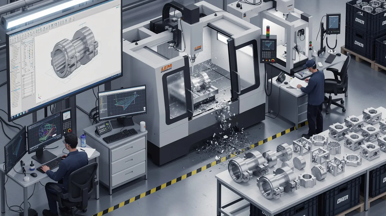
Machining for Manufacturing: From CAD File to Finished OEM Parts
Introduction: Why Machining Still Powers Modern Manufacturing
Machining for manufacturing remains the backbone of precision parts production across aerospace, automotive, medical devices, electronics, and industrial equipment. The aerospace parts manufacturing market alone was estimated at $1,003 billion in 2025, and the global precision machining market was valued at $123.54 billion in the same year – projected to reach $228.75 billion by 2033. These numbers reflect a simple reality: when parts must meet exact specifications, machining is how they get made.
At its core, machining is a subtractive manufacturing process. A cutting tool removes material from a raw material – bar stock, plate, or a casting – to produce components with precise dimensions, tight tolerances, and controlled surface finish. Whether it’s a five-axis CNC mill carving an aluminum aerospace bracket or a CNC lathe turning a stainless-steel shaft, the principle is the same: controlled material removal until the workpiece reaches its desired shape.
OEMs sourcing precision parts globally face recurring problems: late deliveries due to multiple supplier handoffs, out-of-tolerance features caused by poor machine setup, surface finish defects, and missing material certifications that stall regulatory submissions. Robust machining processes – backed by documented workflows and consistent quality control – prevent these issues before they reach your assembly line.
Anebon Metal Products Limited, founded in 2010 in Dongguan, China, is an ISO 9001:2015 and ISO 14001:2015 certified precision CNC machining and fabrication partner serving overseas OEMs. Anebon combines CNC machining, die casting, and sheet metal fabrication under one roof, with tolerances as tight as ±0.002 mm across 75+ materials.
Here’s what this article covers:
-
What machining is and where it fits among manufacturing methods
-
The CAD-to-finished-part workflow
-
Core and advanced machining operations
-
Cutting tools, materials, and machinability
-
Machine setup, quality assurance, and process control
-
Real-world industry applications and DFM guidelines
-
How to choose the right machining partner for OEM production
What Is Machining in Manufacturing?
Machining is a family of subtractive processes that remove material from a workpiece to meet specific dimensions, tolerances, and surface finishes. Standard machining operations achieve tolerances of ±0.05 mm for general features, while precision machining can hold ±0.01 mm – and in some cases ±0.002 mm on critical geometries. Surface roughness after conventional cutting typically falls between 1.6–3.2 µm Ra, with finishing passes reaching 0.8 µm Ra for sealing surfaces. Machining tools date back to 1200 BC, and John Wilkinson invented a boring machine in 1775 that enabled precision bore work for early steam engines – the concept of controlled removal has been refined for centuries.
Machining refines rough surfaces left by raw fabrication methods like casting, forging, or stamping. OEMs often combine these approaches: a part may be die cast for near-net shape, then machined on critical faces to achieve the dimensional accuracy that the casting alone cannot deliver. Additive manufacturing began to complement machining in the 2000s, and today 3D printing handles complex internal geometries while machining handles the tight-tolerance interfaces.
|
Method |
Process Type |
Typical Tolerance |
Best For |
|---|---|---|---|
|
CNC Machining |
Subtractive |
±0.01–0.002 mm |
Precision features, sealing faces, bores |
|
Additive (3D Printing) |
Additive |
±0.1–0.3 mm |
Complex internal geometries, prototyping |
|
Die Casting |
Forming |
±0.05–0.2 mm |
High-volume near-net-shape parts |
|
Forging |
Forming |
±0.5–1.0 mm |
High-strength structural components |
Machining applies to metals, engineering plastics, and some composites. It is especially important for tight-tolerance features like bearing fits, sealing faces, and precision bores. For overseas buyers, well-documented machining processes simplify PPAP, FAI, and regulatory submissions – every dimension is traceable to a specific machine, operator, and inspection report.
From CAD Model to Chips: How the Machining Workflow Actually Works
The path from a customer’s computer aided design file to a finished precision part follows a predictable sequence. Understanding each stage helps OEM engineers anticipate lead times, catch design issues early, and communicate effectively with their machining partner.
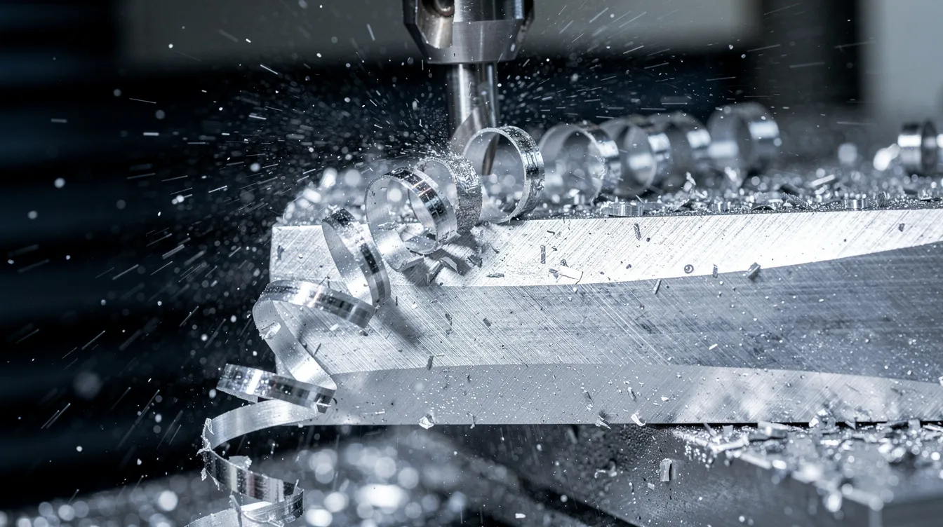
Here is the step-by-step workflow:
-
DFM Review: Engineers analyze the CAD model (STEP, IGES, or native format) for manufacturability – flagging features that are difficult or expensive to machine and suggesting alternatives.
-
CAM Programming: Using computer aided manufacturing software, programmers define stock dimensions, select machining tools, generate toolpaths (roughing, semi-finishing, finishing), and post-process G-code for the specific CNC controller (Fanuc, Siemens, Heidenhain).
-
Machine Setup: The operator selects workholding (vise, chuck, soft jaws, or custom fixture), establishes the zero-point datum, loads tool length and diameter offsets, and configures coolant delivery. Robust machine setup is critical for hitting micron-level tolerances.
-
Roughing: High material removal rate passes – often using trochoidal or adaptive milling – clear the bulk of unwanted material. Typical roughing feeds range from 0.4 to 1.25 mm/rev. Cutting speeds in roughing are lower than in finishing to manage tool load and generate heat without damaging the workpiece.
-
Finishing: Lighter passes at finishing feeds of 0.0125 to 0.04 mm/rev bring the part to its final size and surface finish. This is where machinists create precise parts that meet drawing requirements.
-
First-Article Inspection (FAI): The first completed part is fully measured against the drawing before production continues.
-
Production Run: Once FAI is approved, the batch proceeds with in-process checks at defined intervals.
-
Final QA, Packing, and Shipping: Full dimensional reports, material certificates, and packaging per customer specification.
Each step in this manufacturing process carries its own risk. Missing a tool offset by 0.01 mm during setup, for example, can scrap an entire batch. That’s why CNC programming and documented procedures matter.
CNC Machining: The Core Technology Behind Modern Machine Shops
CNC machining – computer numerical control machining – is the principal machine tool technology behind modern manufacturing. CNC machines use programmed instructions to automate tool movement, replacing the hand cranks and manual dials of traditional machining with digital precision. CNC machining operates 75–300% faster than manual methods, and CNC machines can produce complex geometries with minimal operator intervention.
The difference between manual machining and CNC machining is stark. A machinist running a manual knee mill might spend 45 minutes setting up and cutting a single aluminum bracket. The same part on a CNC vertical machining center runs in under 10 minutes once programmed – and produces identical results on the hundredth part as on the first. CNC machining automates tool paths and reduces manual intervention, which is why it dominates production environments.
Common CNC machine types include:
-
CNC milling centers (3-axis, 4-axis): the workhorse for housings, brackets, and flat surfaces
-
CNC lathes and turning centers: for cylindrical parts like shafts, pins, and hydraulic cylinders
-
5-axis machining centers: for complex 3D surfaces and undercuts in a single setup
-
Mill-turn machines: combining milling and turning to reduce re-clamps and tolerance stack-up
CNC machining achieves tolerances of ±0.025 mm as standard, with tighter holds possible on specific features. Modern machine shops run 24/7 lights-out machining with automatic tool changers, bar feeders, and pallet systems, maximizing production efficiency.
Anebon uses multi-axis CNC machining – including 5-axis capability – for both rapid prototyping and full production runs. This allows engineers to move from a single prototype to thousands of precision parts without changing the fundamental process.
Key Machining Operations Used in Manufacturing
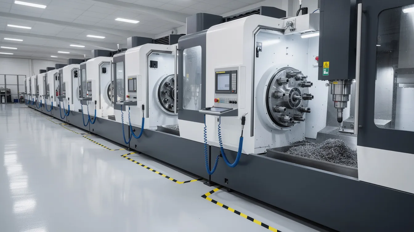
Most machined parts are produced with a combination of standard machining operations on CNC machines. The best machining technique depends on part geometry, material, and production volume. Here are the core operations and where they apply:
-
Turning: The workpiece rotates while a single point tool or cutting tool removes material to create cylindrical features. Turning rotates the workpiece while a cutting tool removes material – used for shafts, pins, bushings, and medical implant screws. CNC lathes are the principal machine tool for this operation.
-
Milling: A rotating cutting tool moves across the workpiece to remove material. Milling uses a rotary cutting tool for flat surfaces, complex 3D contours, slots, and pockets – applications include automotive gearbox housings, electronics enclosures, and aerospace brackets. Milling machines and milling tools handle everything from rough pocketing to mirror-finish surfacing.
-
Drilling: Creates holes using a rotating bit brought axially into the workpiece. Drilling tools – twist drills, step drills, gun drills – create round holes for fasteners, fluid passages, and sensor mounts. You can also cut round holes in sheet metal using specialized approaches.
-
Boring: Enlarges an existing hole to precise dimensions using a single point tool, critical for bearing bores and cylinder liners.
-
Reaming: A finishing operation to bring round holes into tight tolerance bands with improved surface finish on the internal surface.
-
Tapping and Threading: Cuts internal threads for fastener engagement – essential for virtually every assembled product.
-
Counterboring and Countersinking: Creates stepped recesses for fastener heads to sit flush with a rotating cutting surface or specialized tooling.
Combining multiple machining operations in one setup – for example, on a mill-turn machine – improves dimensional accuracy and reduces cost. Fewer re-clamps mean less stack-up error, and the part spends less time traveling between machines.
Advanced and Non-Traditional Machining Processes
When geometry, tolerances, or material hardness push beyond what conventional cutting tools can achieve, non-traditional machining processes step in.
Electrical discharge machining (EDM) uses controlled electrical sparks to erode conductive materials without mechanical contact. Wire EDM cuts complex profiles in hardened tool steels and mold components; sinker EDM creates sharp internal corners and intricate cavities impossible for any rotary cutting tool. Discharge machining works only on conductive workpiece material – it won’t cut ceramics or plastics – but it handles hardened steels above 60 HRC where milling tools would shatter.
Laser cutting uses a focused laser beam to cut sheet metal profiles without hard tooling. It’s ideal for electronics enclosures, brackets, and chassis components in steel, stainless, and aluminum. Complex 2D shapes that would require expensive stamping dies for mass production can be laser-cut economically in low-to-mid volumes.
Water jet cutting (waterjet cutting) is a cold-cutting method complementary to laser cutting. Waterjet cutting is ideal for materials that are difficult to cut thermally – thick aluminum, composites, and heat-sensitive alloys that would warp under a laser beam.
Anebon combines CNC machining with laser cutting, EDM, and surface grinding to move from flat laser-cut blanks to fully machined, formed, and finished assemblies – all under one roof.
Cutting Tools, Drilling Tools, and Grinding Tools: The “Sharp End” of Machining
Tool selection determines whether a job hits its cost, quality, and reliability targets. The cutting tool is where the physics of machining actually happen – tool geometry, material grade, and coating directly affect surface finish, tool life, and cycle time.
Key cutting tool categories:
-
Single-point tools: Used on CNC lathes for turning. The tool geometry of the insert determines chip formation and achievable surface quality.
-
Multi-point tools: End mills, face mills, and other milling tools with multiple cutting edges. A rotating cutting tool with more flutes can handle higher feed rates but may struggle in deep pockets.
-
Drilling tools: Twist drills, step drills, and gun drills. Standard drilling tools create round holes; gun drills handle deep-hole drilling in hydraulic cylinders and firearm barrels.
-
Grinding tools: An abrasive wheel removes micro-layers of material after heat treatment or EDM. Grinding uses abrasive wheels to achieve very low surface roughness – for example, Ra 0.2–0.4 µm on hydraulic shafts or medical device components where an abrasive wheel is the only practical finishing method.
In production, the choice between indexable carbide inserts and solid carbide tools matters. Indexable inserts suit high-volume steel turning where an edge can be rotated four times before replacement. Solid carbide end mills are preferred for high-precision micro-features in titanium or plastics where tool rigidity is paramount. Specialized tooling is often required for exotic alloys and other materials.
Modern CNC machines use tool life monitoring, tool presetters, and in-machine probing to keep dimensions stable throughout long production runs – maintaining tight tolerances without stopping the machine.
Materials and Machinability: Matching Process to Workpiece
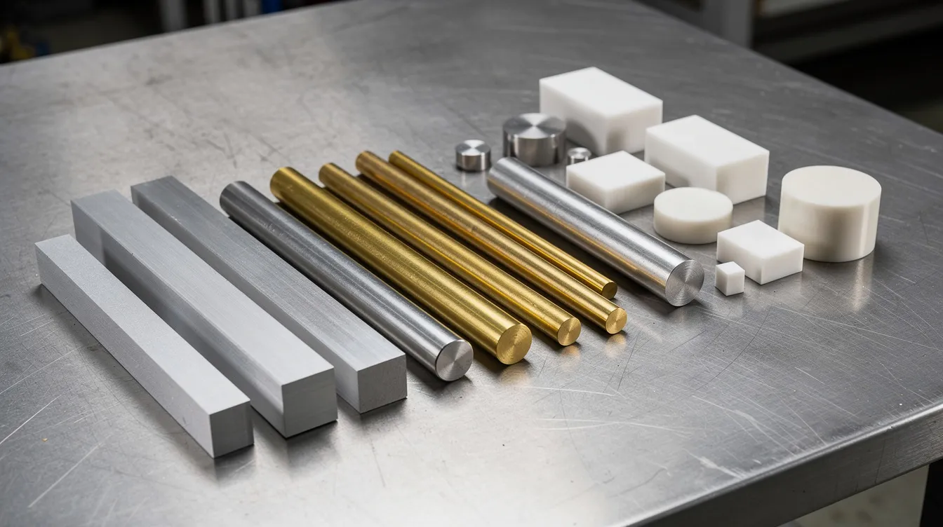
Machinability strongly influences cycle time, tool wear, and achievable tolerances. Material versatility allows machining of metals and non-metals, but OEM engineers should select materials with both performance and manufacturability in mind. Machining supports a wide range of materials including metals and plastics.
|
Material Group |
Common Grades |
Typical Processes |
Key Industries |
|---|---|---|---|
|
Aluminum alloys |
6061-T6, 7075-T6 |
CNC milling, turning |
Aerospace, robotics, electronics |
|
Stainless steels |
304, 316L, 17-4PH |
CNC turning, milling, grinding |
Medical, food processing |
|
Carbon steels |
1045, 4140 |
Turning, milling, grinding |
Automotive, industrial machinery |
|
Brass and copper |
C360, C110 |
CNC turning, milling |
Electronics, plumbing |
|
Titanium |
Ti-6Al-4V |
5-axis milling, turning |
Aerospace, medical implants |
|
Engineering plastics |
POM, PEEK, nylon, ABS |
CNC milling, turning |
Medical, electronics |
|
Alloys metals (Inconel, Hastelloy) |
718, X |
EDM, grinding, slow milling |
Aerospace, energy |
Metals like steel and aluminum are commonly machined materials. Titanium is strong, lightweight, and machinable but expensive – it requires specialized tooling and reduced cutting speeds. Engineering plastics such as PEEK and nylon are machinable but present challenges: heat buildup, burrs, and dimensional shifts require sharp cutting tools and optimized feeds. Ceramics and composites can also be machined with specialized tools, though they often demand diamond-coated tooling.
Material choice drives process selection: very hard alloys metals may require EDM or grinding to shape metals effectively; softer aluminum alloys allow aggressive CNC milling and turning; thin sheet metal is often cut by laser cutting then machined locally on critical features.
Machine Setup, Fixturing, and Process Control on the Shop Floor
Machine setup is a critical step that bridges CNC programming and actual chip cutting. Selecting the right CNC machine, fixtures, and operation sequence minimizes setups and protects critical tolerances. Machining requires proper setup for dimensional accuracy.
Workholding methods include:
-
3-jaw and 4-jaw chucks for cylindrical parts on lathes
-
Collets for small-diameter high-precision turning
-
Vises with precision parallels for prismatic parts on milling machines
-
Custom fixtures for complex or thin-walled components
-
Vacuum fixtures for thin plates prone to deflection
-
Zero-point clamping systems for quick changeovers during mixed production
Precise fixture design and tool offset management reduce scrap and rework during mass production. When fixtures locate parts consistently on the same datum planes, every part in a batch meets the same exact specifications. Modern CNC machining achieves tolerances as tight as ±0.025 mm when setup procedures are followed rigorously.
Process control on the shop floor includes in-process measurement, SPC charts for critical dimensions, tool wear compensation, and controlled cutting parameters – speed, feed, depth of cut, and coolant delivery. ISO 9001:2015-certified shops like Anebon document machine setups and control plans so repeat orders years later can match the original parts exactly. This is what separates a reliable manufacturing process from a one-off success.
Quality Assurance in Machining for Manufacturing
High-precision machining is only as good as the inspection that verifies it. Precision parts destined for OEM assemblies must be backed by traceable quality control data.
Key inspection tools used in a modern machine shop:
-
Digital calipers and micrometers for quick dimensional checks
-
Bore gauges and height gauges for internal features and datum references
-
CMMs (Coordinate Measuring Machines) for full 3D verification of complex geometries
-
Optical comparators for profile inspection
-
Surface roughness testers for verifying Ra values on critical faces
For overseas OEM work, typical QA processes include incoming material inspection with mill certificates, in-process checks at defined intervals, first-article inspection with full dimensional reports, and final inspection before packing. ISO certifications ensure quality and environmental standards for machining services – they’re not just wall decorations.
Industry-specific documentation matters too: PPAP packages for automotive, material and biocompatibility traceability for medical devices, and FAI reports per AS9102 for aerospace. Machining data – tool paths, offsets, inspection results – feeds directly into these submissions. Anebon’s ISO 9001:2015 and ISO 14001:2015 systems ensure consistent machining quality and environmentally responsible processes from prototype to mass production.
Where Machining Shows Up in Real Products and Industries
Machined parts are often hidden inside assemblies, but they are critical for performance and safety. Machining is essential for aerospace, automotive, medical, and electronics industries. Here’s where machining for manufacturing delivers the most value:
-
Aerospace and Defense: Machined titanium structural fittings, aluminum drone frames, and Inconel turbine components. The aerospace industry demands the tightest tolerances and full traceability.
-
Automotive and E-Mobility: Transmission housings, brake caliper bodies, EV motor components – all requiring dimensional accuracy across high production volume runs.
-
Medical Devices: Machining is essential for medical equipment manufacturing requiring tight tolerances. Titanium orthopedic implants, surgical instrument handles, and fluidics manifolds in 316L stainless steel.
-
Electronics: Aluminum heat sinks, connector housings, and EMI shield enclosures machined from custom components specifications.
-
Robotics and Industrial Machinery: Precision gears, linear guide mounts, and actuator housings. Industrial equipment relies on machined components for operational efficiency.
-
Food Processing: Food-grade applications require machined parts from FDA-compliant materials – typically 316L stainless steel with fine surface finish to prevent bacterial traps.
Anebon focuses on OEM and R&D projects where small design iterations and rapid prototyping via CNC machining are needed before scaling to full production. Machining provides superior surface finishes compared to other methods, which is why even die-cast parts often receive secondary machining on mating surfaces.
Design for Manufacturability (DFM) in Machined Components
Thoughtful design choices can dramatically cut machining cost and lead time while maintaining functionality. This is especially important for overseas OEM projects where each design revision adds shipping time and communication cycles.
Practical DFM guidelines for machined parts:
-
Tolerances: Only apply tight tolerances where functionally required. Specifying ±0.01 mm everywhere when ±0.05 mm would work multiplies cost with zero performance benefit.
-
Hole sizes: Standardize to match standard drilling tools – non-standard diameters require custom reamers or boring setups.
-
Internal corners: Add generous radii (at least matching the end mill radius) instead of sharp corners that require electrical discharge machining to achieve the desired form.
-
Deep cavities: Keep depth-to-width ratios below 4:1 where possible. Deeper pockets need longer tools that risk deflection and chatter.
-
Wall thickness: Maintain minimum 0.8 mm for metals and 1.5 mm for plastics to ensure rigidity during cutting. Thin walls vibrate, producing poor surface finish and out-of-tolerance dimensions.
-
Datum selection: Design for consistent datum planes that match assembly requirements. Locating critical features in a single setup reduces accumulated error.
Part orientation and fixture strategy should be considered during design, not after. A part that requires five setups could often be redesigned for two – cutting cost and improving accuracy.
Anebon’s engineering team provides DFM feedback before machining begins, reviewing customer CAD data to flag risk areas and suggest cost-effective changes. This front-end investment routinely saves 15–30% on production costs.
Choosing a Machining Partner for OEM Manufacturing
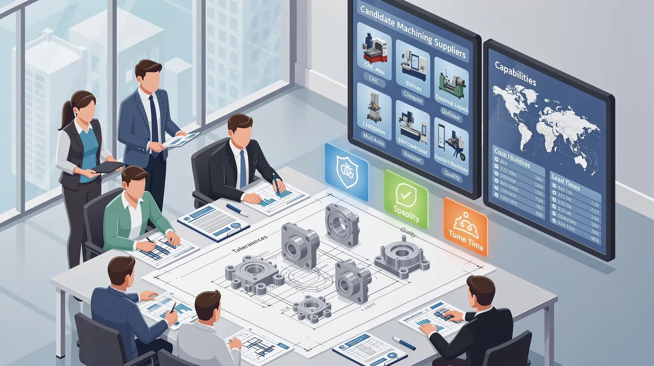
Selecting the right machining vendor is one of the highest-leverage decisions an OEM engineering team makes. Here’s what to evaluate:
Technical capability:
-
Range of CNC machines (3-axis through 5-axis), age and condition of equipment
-
In-house vs. outsourced processes – EDM, laser cutting, grinding, and surface treatments
-
Supported materials and maximum part size
-
Machining is ideal for producing complex geometries and features – make sure your partner can handle yours
Quality and documentation:
-
ISO certifications (9001 for quality, 14001 for environmental management, 13485 for medical)
-
Inspection equipment (CMM, surface testers, optical)
-
FAI and PPAP experience for your specific industry
Logistics and communication:
-
Sample and production lead times
-
Packaging standards for international shipping
-
English-speaking engineering contacts for DFM discussions
-
Experience with customs documentation
Working with an integrated manufacturer that offers CNC machining, die casting, and sheet metal fabrication under one roof reduces handoffs between suppliers. A European medical device OEM that consolidated from three suppliers to one integrated partner reported a 35% reduction in time to market and dramatically improved quality consistency.
Anebon Metal Products Limited offers exactly this integration. To get started, send your CAD files and specifications for a detailed CNC machining quote with DFM feedback.
FAQ: Practical Questions About Machining for Manufacturing
What is the difference between CNC machining and manual machining for production? Manual machining relies on an operator to control feeds and movements by hand, which limits repeatability and speed. CNC machining uses programmed instructions to produce identical parts with minimal operator intervention. CNC machines run 75–300% faster than manual methods and maintain tolerances of ±0.025 mm across entire production runs.
What tolerances can Anebon typically hold on CNC machined parts? Standard precision parts are held to ±0.01 mm on critical dimensions. On suitable geometries and materials, Anebon achieves tolerances as tight as ±0.002 mm. Modern machining achieves tolerances of ±0.025 mm as a baseline across most operations.
When should I choose electrical discharge machining instead of standard cutting tools? Choose EDM when you need sharp internal corners, very fine features in hardened steels (above 55 HRC), or geometries that no rotary cutting tool can reach. EDM uses controlled electrical sparks to erode material without mechanical force, making it ideal for mold cavities and thin-wall features.
Can you combine laser cutting and CNC machining on the same part? Yes. Laser cutting handles 2D profiles in sheet metal efficiently, and CNC machining adds precision features – tapped holes, counterbores, and machined datum surfaces. Anebon routinely produces parts using both processes.
How do machining costs change between prototype and mass production? Prototypes carry higher per-unit cost due to programming, setup, and FAI time spread across one or a few parts. In mass production, these fixed costs amortize, and production efficiency increases with optimized toolpaths and fixtures. Production volume directly influences unit cost.
Which CNC machines are best for complex 3D surfaces? Five-axis machining centers allow the cutting tool to approach the workpiece from virtually any angle, eliminating multiple setups and producing complex 3D contours in a single clamping. They shape materials into their desired form that would require three or four setups on a 3-axis machine.
Sending a 3D model and quantity estimate is the fastest way to get accurate DFM feedback and pricing from Anebon Metal Products Limited. Request a quote today.