Essential Guide to Fabricated Sheet Metal: Processes and Applications
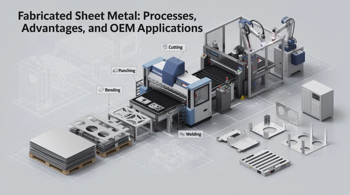
Fabricated Sheet Metal: Processes, Advantages, and OEM Applications
Introduction to Fabricated Sheet Metal
Fabricated sheet metal is a process of turning flat metal sheets into functional parts that power everything from industrial machinery enclosures to the chassis inside your smartphone. This article answers two core questions: what fabricated sheet metal is and how the sheet metal fabrication process works from raw material to finished component.
Metal fabrication is a family of processes – cutting, forming, joining, and finishing – applied to thin metal sheets typically ranging from 0.3 to 6 mm in material thickness. These operations transform simple flat stock into precision parts with complex features, tight tolerances, and application-specific finishes. With the global sheet metal fabrication market projected to exceed £15 billion by 2030, understanding these processes is essential for any OEM design team evaluating manufacturing partners.
Anebon Metal Products Limited is an ISO 9001:2015 and ISO 14001:2015 certified precision metal fabrication partner founded in 2010 in Dongguan, China. From rapid prototyping through full-scale production, Anebon serves overseas OEMs with sheet metal fabrication capabilities that include laser cutting, CNC bending, welding, surface treatment, and integration with CNC machining and die casting.
-
What this sheet metal guide covers: definitions, core processes, materials, DFM rules, and applications
-
Who it’s for: OEM design engineers, R&D teams, and purchasing managers evaluating fabrication partners
-
Key theme: how to move from concept to end use production efficiently and cost effectively
What Is Fabricated Sheet Metal?
Fabricated sheet metal refers to the transformation of flat metal sheets into functional sheet metal components via metal fabrication processes such as laser cutting, mechanical cutting, bending, welding, and surface finishing. Common methods in sheet metal fabrication include laser cutting and CNC machining, often combined in a single production routing.
The distinction matters: “sheet metal” describes the raw material form – flat stock delivered in coils or blanks. “Fabricated sheet metal” describes the finished or semi-finished sheet metal parts ready for assembly or end use production. These parts can be tailored for specific mechanical or aesthetic requirements depending on the application.
Typical thickness ranges vary by industry. Consumer electronics housings often use 0.5–3.0 mm stock, while enclosures for industrial machinery may call for material up to roughly 6 mm. Sheet metal fabrication is widely used for enclosures, brackets, and structural components across nearly every manufacturing sector.
Common fabricated sheet metal products include:
-
Brackets and mounting plates – sensor mounts, motor brackets, wall-mount hardware
-
Enclosures and chassis – control cabinets, server housings, metal boxes for electronics
-
EMI/RFI shields – conductive enclosures that block electromagnetic interference
-
Bus bars – copper or brass conductors for power distribution
-
Structural frames – welded assemblies for robotic arms, machine bases, and automotive substructures
-
Storage tanks and containers – sheet metal fabrication produces containers for food and chemicals
Key Advantages of Sheet Metal for OEM Designs
The advantages of sheet metal explain why it dominates so many industries, from automotive to aerospace. Sheet metal fabrication produces highly durable parts that combine structural performance with manufacturing efficiency in ways few other processes match.
High strength-to-weight ratio is a key advantage of fabricated sheet metal. Folded geometries, ribbed panels, and strategic bends create stiffness without adding excessive mass, which is why over 50% of car parts are made from sheet metal. Design flexibility is another draw: cut-outs, louvers, embosses, and mounting features can be added without expensive dedicated tooling, making custom sheet metal projects cost effective even at moderate volumes.
-
Strength and stiffness – bent or formed sheet metal structures rival heavier alternatives in load-bearing performance
-
Design flexibility – features are programmed digitally, not machined into hard tooling, so design changes are fast and inexpensive
-
Scalability – the same design can move from 1–10 prototype pieces to 10,000+ production parts with consistent quality
-
Rapid turnaround – sheet metal fabrication allows for rapid prototyping and production, compressing development timelines
-
Recyclability – metals like aluminum and stainless steel are highly recyclable; nesting software for laser cutting can yield 70–90% material utilization, though the process can generate scrap waste during cutting
-
Finish compatibility – sheet metal accepts powder coating, anodizing, plating, and other treatments for both functional and decorative elements
Core Metal Fabrication Processes for Sheet Metal
Fabricated sheet metal relies on multiple metal fabrication processes often combined into a single routing to produce the final geometry. Designers use CAD software to create 3D models, which are then translated into machine instructions through CAM programming before any raw materials are touched.
The main stages in a typical sheet metal fabrication process are:
-
CAD/CAM design – 3D modeling, flat-pattern development, and nesting for material yield
-
Cutting – laser cutting, mechanical cutting, or plasma cutting to shape the blank
-
Forming and bending – press brakes, rollers, and stamping to create 3D features from flat stock
-
Joining and assembly – welding, riveting, or hardware insertion to combine sheet metal parts into metal structures
-
Surface finishing – powder coating, anodizing, chem film, plating, or standard painting methods for protection and aesthetics
Anebon integrates CNC machining and die casting where needed, creating hybrid assemblies that combine fabricated sheet metal components with machined precision parts or cast housings. Different industries emphasize different steps: a structural frame for industrial machinery demands heavy welding and load testing, while a small consumer electronics bracket may skip welding entirely and rely on self-clinching hardware. Fabrication processes like stamping and laser cutting become economical for medium to large production runs, while CNC-based methods keep low volume prototypes viable.
Cutting Processes: Laser Cutting vs Mechanical Cutting
The cutting step is critical because it establishes the dimensional accuracy, edge quality, and downstream fit of every fabricated sheet metal part. Poor edge quality leads to weld defects, misaligned bends, and rejected assemblies, so material selection for the cutting method matters as much as the material itself.
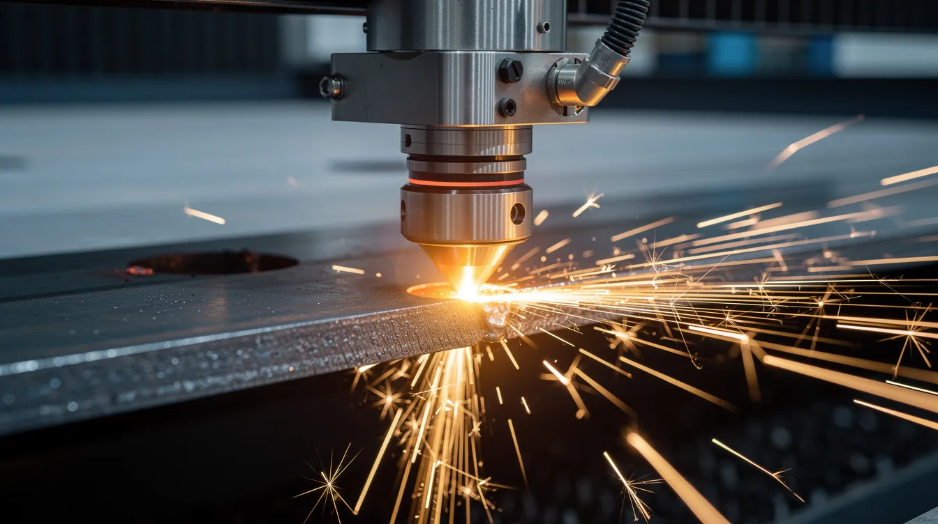
Laser cutting uses a CNC-controlled fiber laser to trace complex 2D profiles with minimal burr and tight tolerances (typically ±0.1–0.25 mm on flat dimensions for thin sheet). A laser cutter can cut steel sheet metal and aluminum with a narrow kerf and clean finish. Laser cutting can cut through metals up to 30 mm thick, though most sheet metal fabrication work stays below 6 mm. The cutting head follows programmed contours with no dedicated tooling, making it ideal for prototypes and design iterations.
Mechanical cutting – shearing, punching, and turret punching – excels at high volume production runs with simple, repetitive features like holes, slots, and straight axis cuts. Tooling cost is higher upfront but amortizes quickly over thousands of parts. Waterjet cutting can cut metals up to 300 mm thick, making it suitable for thicker materials that exceed what lasers handle efficiently.
Key comparisons between these sheet metal fabrication techniques:
-
For complex 2D profiles and quick design changes, laser cutting is usually more cost effective than building dedicated punch tooling
-
Mechanical cutting avoids the heat-affected zone (HAZ) that thermal processes introduce, preserving material properties at the cut edge
-
Plasma cutting offers lower hourly rates (~$40–80/hr) but delivers looser tolerances and rougher finishes than laser
-
Punching is faster per piece in high volumes once tooling is amortized, making it preferable for creating parts with many identical features
-
Laser cutting requires very little thickness-specific tooling, while punch dies must match each feature geometry exactly
Forming, Bending, and Other Sheet Metal Fabrication Processes
Once blanks are cut, forming operations transform flat metal sheets into three-dimensional sheet metal components. This is where a part gains its desired shape – the flanges, channels, and enclosure walls that define its function. Complex geometries are difficult to achieve with sheet metal compared to casting or machining, but experienced sheet metal fabricators use a combination of techniques to push the limits of what’s possible.
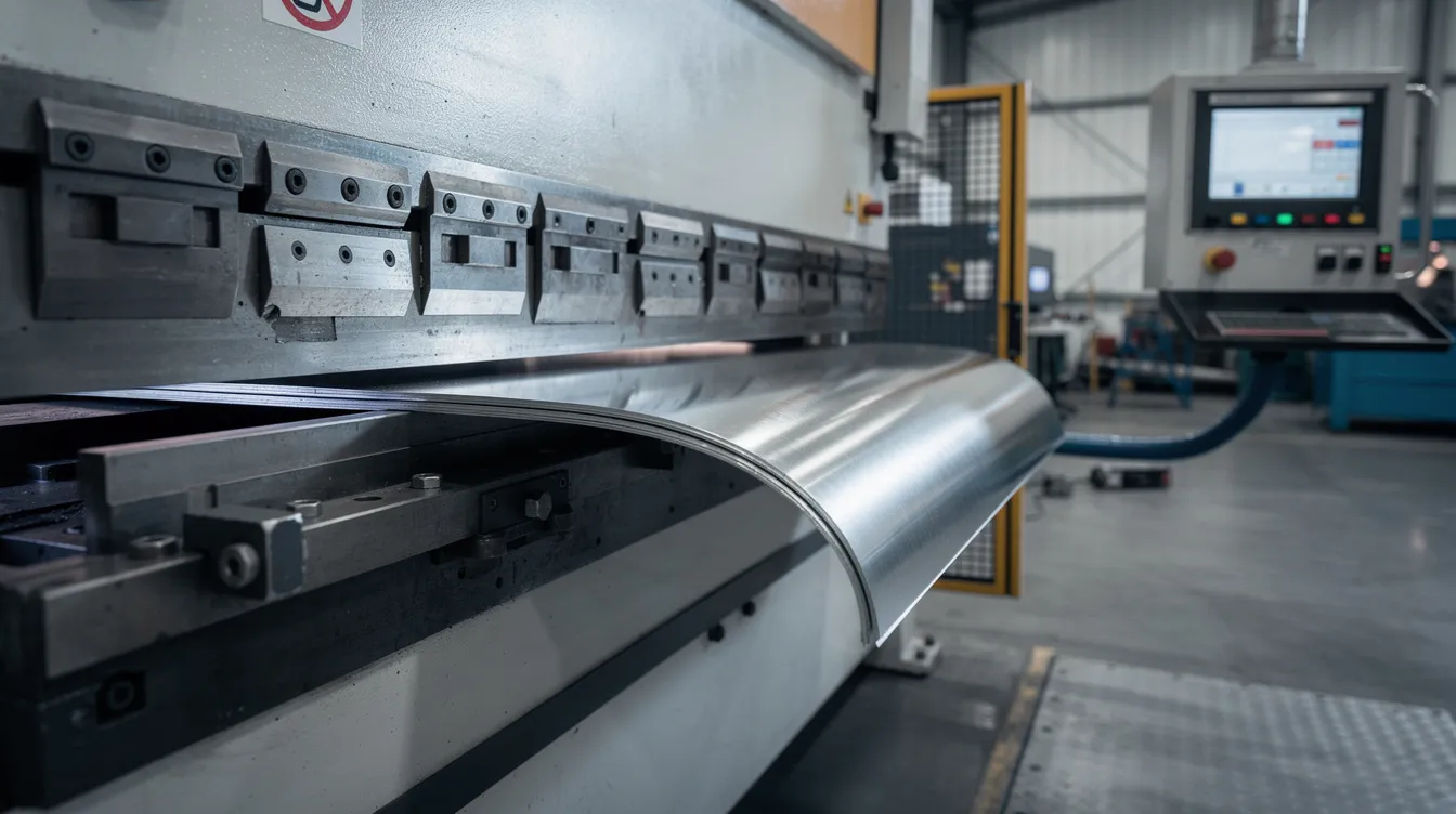
Press brake bending is the most common forming operation. A punch presses the workpiece into a die along a straight axis, producing bends at programmed angles. Bend radii must be carefully managed during sheet metal fabrication to avoid cracks; inside radius is typically specified as 1× to 2× the material thickness. Bending techniques include V-bending, U-bending, and roll bending, each suited to different flange lengths and angles. Understanding which tool is used to bend sheet metal helps engineers select the right approach for their part geometry.
-
Springback – after the punch retracts, elastic recovery shifts the bend angle. This anisotropic springback behavior must be compensated for to achieve precise angles in bending, typically by overbending or using angle-sensing feedback on CNC press brakes
-
Stamping – sheet metal stamping presses a shape into a workpiece using a die, ideal for high-volume runs where tooling cost can be spread across thousands of units
-
Rolling – curves blanks into cylindrical or conical forms for storage tanks, ductwork, and similar round structures
-
Embossing and deep drawing – create stiffening ribs, decorative elements, or deep cup-shaped features from flat blanks
-
Anebon’s approach – CNC press brakes and automated bending cells deliver repeatable angles and rapid changeovers, supporting both prototypes and production volumes with consistent results
Joining and Assembly of Fabricated Sheet Metal
Fabricated sheet metal parts frequently require assembly into chassis, housings, and larger metal structures. The joining method directly affects strength, appearance, cost, and serviceability, so OEM engineers must choose carefully based on the application.
Common joining methods include:
-
TIG welding – tungsten inert gas welding delivers clean, precise welds on thin materials including stainless steel and aluminum; preferred for visible seams and parts requiring a high desired aesthetic
-
MIG welding – metal inert gas welding is faster and more cost effective for thicker joints and longer seams; welding sheet metal with a MIG welder is common in structural assemblies
-
Spot welding – fast, automated resistance welding for overlapping steel sheets; widely used in automotive body panels
-
Riveting and bolted joints – mechanical fastening preferred when parts need disassembly for servicing, or when joining dissimilar metals
-
Self-clinching hardware (PEM inserts) – pressed into the part surface to provide threaded mounting points without welding
Welding joins metal parts by melting joint edges to fuse them, but thin sheet metal requires care. Parts are often tack welded first, then sequentially welded to distribute heat and minimize distortion. In some cases, post-weld straightening or heat treatment is necessary to restore flatness. When heat input must be avoided entirely – near sensitive electronics or coatings – mechanical fastening is the better path.
Anebon delivers fully fabricated assemblies, including integration with CNC machined and die cast metal components, reducing the number of vendors an OEM must manage.
Surface Treatments: From Powder Coating to Chem Film
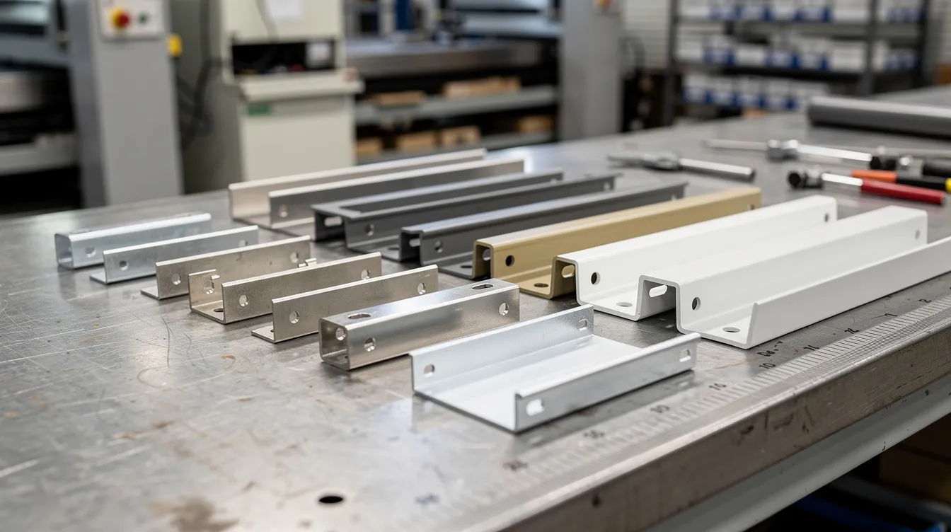
Surface treatment is essential for corrosion resistance, aesthetics, and electrical performance. A bare fabricated sheet metal part is rarely ready for deployment without some form of protective or functional finish. Surface finishing options include powder coating, anodizing, and plating for protection and aesthetics, as outlined in this sheet metal surface treatment manual.
Powder coating applies electrostatically charged powdered paint to the part surface, which is then cured in an oven at 150–200°C. The result is a 50–100 µm thick corrosion resistant finish with wide color options. Powder coating creates a durable, corrosion resistant layer that outperforms standard painting methods in scratch and UV resistance. It’s the go-to for industrial machinery panels, outdoor enclosures, and any part requiring a tough decorative finish.
Anodizing is specific to aluminum. Anodising produces a corrosion resistant oxide layer on metals through an electrochemical process:
-
Type II anodizing is decorative, with thickness ranges from 0.0025 mm to 0.0013 mm, offering color options and moderate wear protection for consumer electronics housings and architectural trim
-
Type III anodizing (hardcoat) creates a thicker, wear resistant layer ranging from 25 to 125 µm, providing superior abrasion and corrosion resistance for demanding environments
Chromate conversion coating (chem film) is a thin chemical treatment applied to aluminum, zinc, or magnesium surfaces. It provides a corrosion resistant layer while preserving electrical conductivity – a critical requirement for grounding-critical parts and EMI shields. Coatings conform to MIL-DTL-5541, with Class 1A offering maximum corrosion protection and Class 3 prioritizing lower electrical resistance.
Other finishes Anebon provides:
-
Electroplating – deposits a thin layer of metal onto surfaces for wear resistance or conductivity; nickel and zinc plating are common
-
Brushing and polishing – brushed stainless steel (#4 finish) for visible consumer electronics surfaces; mirror polishing for copper or brass
-
Laser marking – permanent part identification for traceability without affecting the part surface integrity
-
Bead blasting – plastic beads or glass media create a uniform matte texture before coating
Materials and Material Thickness Selection
Performance and cost in any sheet metal fabrication project depend heavily on material selection and material thickness. The choice of materials impacts factors like strength, weight, and corrosion resistance in fabrication, so getting this right early in the design phase prevents expensive revisions later.
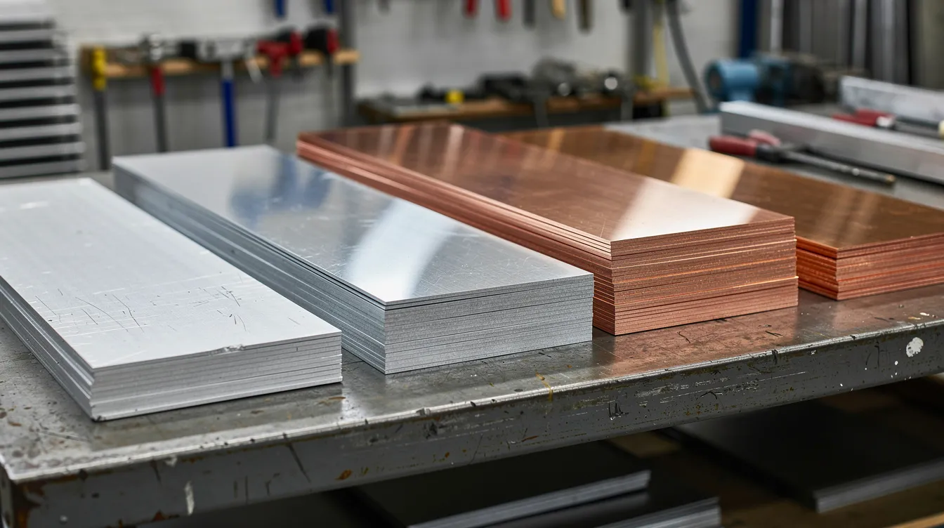
Materials used in sheet metal fabrication include steel, aluminum, copper, and brass. Here’s how each stacks up:
-
Carbon steel and cold-rolled steel – steel is commonly used for its strength and durability in various applications; hot rolled steel works for structural frames, while cold-rolled offers better surface quality; both require coating for corrosion resistance
-
Galvanized steel – pre-coated with zinc for moderate corrosion protection; cost effective for enclosures and brackets
-
Stainless steel (304, 316) – stainless steel is ideal for structural components due to corrosion resistance; harder to cut and bend, with more springback, but excellent for medical, food, and marine environments; learn about the differences between 316 and 316L stainless steel for critical applications
-
Aluminum alloys (5052, 6061-T6) – aluminum is lightweight and corrosion-resistant with good thermal conductivity, making it the default for weight-sensitive applications in aerospace, consumer electronics, and EV components
-
Copper – copper is highly conductive, suitable for electrical applications like bus bars and RF shielding; it has good conductivity properties but lower stiffness
-
Brass – brass is excellent for low-friction applications and artistic uses; common in decorative elements and specialty connectors
Material thickness directly impacts stiffness, weight, bendability, and minimum bend radii. Consumer electronics and IT housings typically use 0.8–1.5 mm stock, while machine guards and engine blocks may require 3–6 mm for structural integrity. As a general rule, thinner material bends more easily but offers less rigidity, while thicker materials demand larger bend radii and more powerful press brakes.
Anebon provides DFM feedback to help customers optimize thickness and alloy grade, balancing performance against manufacturability and cost.
Design for Manufacturability (DFM) in Custom Sheet Metal
Good DFM can reduce cost and lead time for custom sheet metal parts by 20–40% in many cases. Sheet metal design must consider thickness and material type from the earliest engineering drawings, because decisions made in CAD ripple through every downstream operation. Design for manufacturability feedback improves part quality and reduces the risk of rejected parts.
Key design rules every engineer should follow:
-
Minimum hole size – holes should be at least equal to the material thickness in diameter; smaller holes increase tool wear and risk deformation
-
Hole-to-edge distance – minimum hole to edge distance is 2× material thickness to prevent tear-out during punching or bending
-
Bend-to-hole spacing – maintain at least 2× thickness plus the bend radius between a hole and a bend line to avoid distortion
-
Relief cuts – inside corners need relief notches to prevent tearing during forming
-
Standard bend radii – use radii that match available tooling; non-standard radii add cost and lead time
-
Bend angle tolerance – bend angle tolerance is typically ±1.0° for bends under 24 inches; tighter tolerances require slower operations and additional inspection
-
Minimum flange length – flanges should be at least 3–4× material thickness for strength and to allow the press brake die to grip properly
-
Designs must account for manufacturing tolerances to prevent issues during production – especially when multiple bends interact to define the final geometry
Anebon’s engineers routinely review OEM CAD models and provide DFM suggestions before cutting or bending begins. Understanding bend allowance and material consumption for complex folding sequences is part of this process. The goal: eliminate surprises on the shop floor and keep your sheet metal fabrication project on schedule.
From Prototype to End Use Production
The same fabrication route that produces a single prototype can scale to thousands of production parts – the key is planning the transition intentionally rather than treating prototyping and production as separate worlds.
Digital workflows compress this transition. CAD upload, automated quoting, CAM programming, and preliminary DFM feedback happen before a single blank is cut. Anebon supports iterative design: quick prototype runs let R&D teams validate fit and function, followed by design revisions, then locked specifications for production orders.
-
Low volume prototypes need speed and flexibility – manual correction is acceptable, tolerances can be slightly relaxed, and the focus is on proving the concept
-
End use production demands process capability, repeatability, first-article inspection, documented quality control, and optimized nesting for material yield
-
Tooling decisions shift at scale – what works for 10 pieces (laser-only routing) may not be the most cost effective approach for 10,000 pieces (progressive stamping or dedicated punch dies)
-
Anebon’s range spans single prototype units through mass production, with stable tolerances and consistent surface treatments across production volumes
Applications of Fabricated Sheet Metal by Industry
Fabricated sheet metal is foundational across sectors from aerospace to robotics. Wherever metal products must combine structural integrity with precise geometry and manageable weight, sheet metal fabrication techniques are typically involved. Here’s how key industries use these capabilities:
-
Aerospace – sheet metal is used for aircraft bodies and engine components, as well as avionics enclosures, brackets, and ducting; EMI shields with chem film finishes maintain electrical conductivity for sensitive equipment
-
Automotive – over 50% of car parts are made from sheet metal, including body panels, brackets, exhaust heat shields, and EV battery pack enclosures (aluminum and steel welded trays introduced in vehicles launched after 2020, such as next-generation platforms from major automakers)
-
Industrial machinery – machine guards, control cabinets, base frames, and mounting plates; often powder coated for corrosion resistance in factory environments
-
Medical devices – equipment panels, surgical cart frames, and instrument housings; may require ISO 13485:2016 certification for medical device quality management
-
Consumer electronics – laptop chassis, smartphone frames, rack-mount server enclosures, and heat sinks leveraging thermal conductivity of aluminum
-
Marine – sheet metal is essential for marine vehicles like ships and submarines, where corrosion resistant stainless steel and specialized coatings protect against saltwater
-
Food and chemical processing – sheet metal fabrication produces containers for food and chemicals, including high volume production runs of stainless steel vessels and storage tanks
Cost Drivers in Fabricated Sheet Metal
Price in fabricated sheet metal is driven by material type, part size, material thickness, geometry complexity, and secondary operations. Understanding these drivers helps OEM purchasing teams and engineers make informed trade-offs during the design phase rather than after quotes arrive.
-
Material cost – stainless steel and copper cost significantly more per kilogram than carbon steel or aluminum; choosing the right grade prevents over-specifying
-
Cutting method – laser cutting rates run approximately $100–200/hour, CNC punching $80–150/hour, and plasma cutting $40–80/hour; for high volume production runs, the breakeven point for investing in punch tooling versus no-tool laser methods typically falls in the 2,000–5,000 unit range
-
Number of bends – each bend adds a setup or tool change on the press brake; reducing unnecessary bends directly reduces cost
-
Joining labor – welding is labor-intensive; reducing weld length, using self-clinching hardware, or designing snap-fit tabs can cut assembly time
-
Surface treatment – multi-step finishes (e.g., conversion coating plus powder coating) add cost; specifying only what the application demands keeps pricing lean
-
Tolerances – tighter tolerances require slower operations, additional inspection, and sometimes secondary machining; specifying ±0.1 mm where ±0.25 mm would suffice inflates cost without adding value
Anebon provides itemized quotations that break down each cost driver and can suggest design tweaks – such as increasing hole sizes slightly or consolidating bend operations – that reduce fabrication time without compromising performance.
Quality Assurance and Inspection for Fabricated Sheet Metal
Anebon operates under ISO 9001:2015 certification, which ensures quality management standards are maintained across every production run. Calibrated metrology equipment and documented inspection plans govern every stage of the manufacturing process.
Quality control for fabricated sheet metal spans multiple checkpoints:
-
Visual inspection identifies surface defects such as scratches, dents, weld spatter, and finish inconsistencies before processing continues
-
Dimensional inspection ensures parts meet specified tolerances using calipers, micrometers, and coordinate measuring machines (CMMs); critical dimensions are verified against engineering drawings
-
Weld inspection – penetration depth, bead consistency, and distortion are evaluated visually and, for critical parts, via non-destructive testing that detects internal defects without damage
-
Coating verification – thickness of powder coating, anodizing, and chromate conversion coating is measured using eddy current or coulometric methods; adhesion tests and salt-spray testing confirm the corrosion resistant finish meets specification
-
First-article inspection (FAI) – critical parts may receive FAI reports or PPAP-style documentation with full material traceability, including mill certificates for alloy verification
For medical device OEMs, quality management may extend to ISO 13485:2016 certification requirements. For high-volume production, statistical process control and in-line gauging help maintain consistency across thousands of precision parts.
Why OEMs Choose Anebon for Fabricated Sheet Metal
Since 2010, Anebon Metal Products Limited has served as a precision sheet metal and CNC manufacturing partner for overseas OEMs who need reliable, certified fabrication without managing multiple vendors. Our sheet metal fabrication capabilities span the full workflow from design consultation through final assembly and shipping.
What sets Anebon apart as one of the top sheet metal fabrication companies for OEMs:
-
Integrated services – sheet metal fabrication, CNC machining, and die casting under one roof, enabling hybrid assemblies and reducing coordination overhead
-
Tight tolerances – as precise as ±0.002 mm on machined features, with competitive sheet metal tolerances (laser-cut flat features ±0.05–0.1 mm, bend angles ±0.5–1°)
-
Certifications – ISO 9001:2015 for quality management and ISO 14001:2015 for environmental management
-
Industry breadth – aerospace, automotive, medical devices, consumer electronics, robotics, and industrial machinery
-
Full lifecycle support – from low volume prototypes and rapid iteration to high volume production runs with documented quality control and consistent surface treatments
-
DFM feedback – our engineers review your CAD models before production, flagging potential issues and suggesting optimizations that save time and cost
-
Flexible batch sizes – whether you need 5 prototype pieces or 50,000 production parts, the same quality standards apply
Fabricated sheet metal remains one of the most versatile and cost effective routes from concept to production-ready metal components. Whether you’re developing a new product line or optimizing an existing design for manufacturability, the right fabrication partner makes the difference between a smooth launch and costly delays.
Ready to get started? Upload your CAD or STEP files to Anebon for a free DFM review and detailed quotation. Our team is equipped to handle all your manufacturing needs – from first prototype to full-scale production. Request a quote today and see how precision fabrication should work.