Essential Guide to CNC Machining: Processes and Benefits Explained
CNC Machining: A Practical Guide for Engineers, OEMs, and CNC Machine Operators
CNC machining is one of the most versatile processes in the manufacturing industry, yet choosing the right approach for a given project still trips up experienced engineers. This guide covers the core technology, machine types, materials, design rules, and quality practices you need to make informed decisions on your next CNC machining project.
What Is CNC Machining? (Answer the Core Question Immediately)
CNC machining is a subtractive manufacturing process in which pre programmed computer software directs cutting tools to remove material from solid stock, producing finished metal parts or plastic components. CNC stands for computer numerical control-a method that replaced manual control of machine tools with digital computers and, eventually, completely electronic control systems. Where earlier shops relied on analog computers and hand-wheel adjustments, today’s CNC system uses pre programmed software and G code to achieve extreme precision with minimal human intervention.
The CNC machining process starts with a computer aided design (CAD) model that defines part geometry. That model feeds into computer aided manufacturing (CAM) software-often called aided manufacturing CAM software-which acts as a code generator, producing G code instructions the machine follows. The machine then drives milling machines, CNC lathes, or other CNC equipment along multiple axes to cut away raw materials and reveal the finished shape. CNC machining is an automated manufacturing process controlled by computer software, and it is widely used in aerospace and automotive industries, as well as medical, electronics, and robotics sectors.
What makes precision CNC machining valuable is its repeatability. CNC machining achieves tolerances of ±0.001 inches or better, and it produces complex shapes with high accuracy-results that would be nearly impossible to replicate manually on conventional machining equipment. This level of consistency is why industries using CNC machining include aerospace, automotive, medical, and electronics. For a deeper introduction, see Anebon’s overview of what CNC machining is and how it works. Throughout this guide, we use Anebon Metal Products Limited-a Dongguan-based precision CNC machining, die casting, and sheet metal fabrication provider-as a practical example of modern CNC manufacturing capabilities.
How a CNC Machine Works: From CAD File to Finished Part
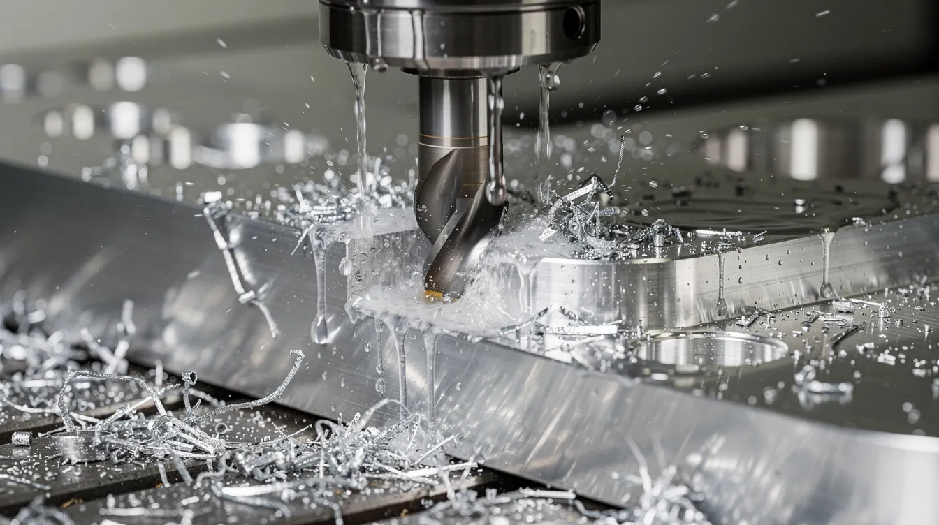
Imagine an engineer in 2026 needs a motor housing machined from 6061-T6 aluminum. She drafts a 3D CAD model-mounting bosses, ventilation slots, assembly interfaces-and imports it into CAM software such as Mastercam or Fusion 360. CAD software creates precise 2D or 3D vector models of components, and the CAM environment translates those designs into G code for the CNC machine. The software simulates roughing passes to strip bulk material, semi-finishing, and finishing passes to hit the specified surface quality. It checks for collisions, calculates spindle RPM, feed rates, and depth of cut, and outputs a program file ready for the shop floor.
The CNC machining process follows a sequence from design to execution. On the machine, a CNC machinist loads the stock into a vise or fixture, mounts cutting tools in the tool changer, zeros the axes, and uploads the program. The CNC system interprets G code line by line, directing servo motors along the X, Y, and Z axes-and rotational axes if the machine supports them. CNC machines can operate along three linear axes and more, depending on the configuration. Modern high-precision CNC machinery uses a closed loop system where encoders feed positional data back to the controller, correcting deviations in real time. This is what separates precision parts from rough cuts.
Who does what? A CNC programmer designs toolpaths in CAM. A CNC machinist handles setup, tooling, offsets, and troubleshooting. A CNC machine operator runs pre-set programs, loads and unloads parts, monitors alarms, and performs basic inspection. CNC machine operators conduct test runs before production starts to verify dimensions, making adjustments before committing to a full batch. For more on how CNC machining works, Anebon maintains a detailed walkthrough.
Main Types of CNC Machines Used in Precision Manufacturing
Different types of CNC machines are optimized for different geometries and production volumes. Many CNC machines in a facility like Anebon’s Dongguan shop run as a mixed fleet-CNC mills alongside turning machines, EDM units, and grinders-so that complex parts can be completed without outsourcing operations.
Here is a breakdown of the primary CNC machinery categories:
-
3-Axis CNC Mills: CNC mills operate on a three-axis system (X, Y, Z). Best for prismatic parts-brackets, plates, housings. Simple CNC programming, low cost, but multiple setups needed for multi-face work.
-
4-Axis CNC Mills: Add one rotational axis for indexing, letting the machine access side features without re-clamping.
-
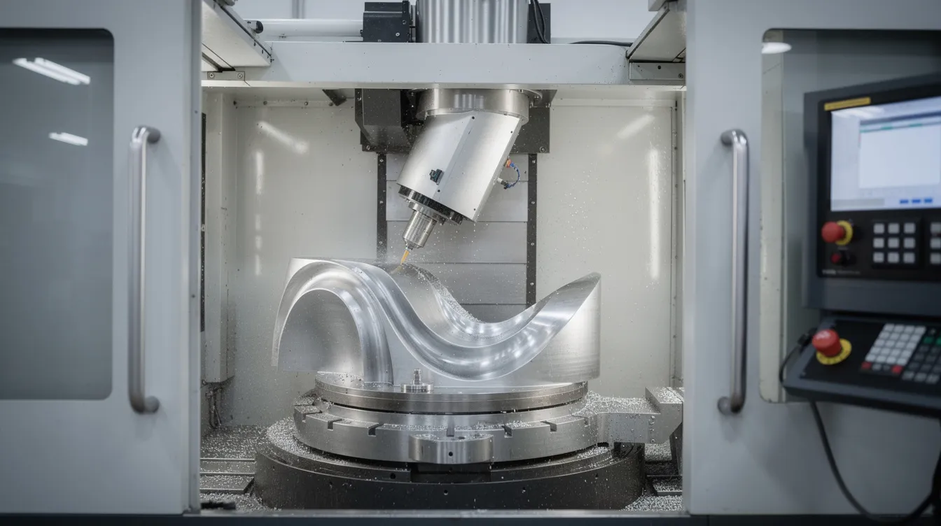
5-Axis CNC Mills: Three linear plus two rotational axes enable multi axis machining of complex geometries-turbine blades, impellers, implant surfaces-in a single setup. Anebon runs 3-axis, 4-axis, and 5-axis machining centers to handle complex OEM components efficiently. Today’s machines combine milling and contouring capabilities that previously required multiple setups on separate CNC equipment.
-
CNC Lathes / Turning Centers: Stock rotates while cutting tools remain stationary or move along linear axes. CNC lathes are used for producing cylindrical parts-shafts, bushings, hydraulic fittings. Live-tool turning machines add cross-drilling and milling on turned parts. Anebon’s CNC precision turned components page shows typical examples.
-
Mill-Turn Centers: Combine turning and milling in one spindle, reducing setups and positional error from re-clamping-a clear example of complex machinery serving advanced jobs.
-
CNC Grinding Machines: Surface, cylindrical, or centerless grinders finish hardened surfaces to mirror-quality roughness and extremely tight tolerances.
-
EDM (Wire EDM & Sinker EDM): Electric discharge machines shape metals using electrical sparks-sometimes called spark machining. Wire EDM threads a thin wire through the workpiece; sinker EDM plunges a shaped electrode. Both excel at hardened steels, sharp edges, and fine slots that conventional cutting tools cannot reach.
-
CNC Routers, Laser Cutting, Plasma Cutters, and Waterjet Cutters: CNC routers handle wood, plastics, and soft metals in large-format sheets. Laser cutting provides precise profiles in sheet metal. Plasma cutters use a plasma torch to cut metal at high speed-common CNC plasma cutters handle thick steel plate. Water jet cutters use high-pressure water (often with abrasive) to cut materials without heat-affected zones.
Common CNC machines include mills, lathes, and plasma cutters, but a comprehensive guide to CNC machining techniques shows how these factory tools work together in a modern shop.
CNC Milling vs. CNC Turning: Choosing the Right CNC Manufacturing Process
Most CNC machining projects use either milling, turning, or a combination. Understanding when each manufacturing process excels saves time and cost.
In CNC milling, the workpiece is fixed while the tool rotates and moves along multiple axes. Milling machines handle contours, pockets, slots, and surface finishing. CNC machining can produce intricate 3D contours and deep pockets that would be impractical on a lathe. A 5-axis milled aluminum heatsink with thin, uniform fin geometry is a typical example.
In CNC turning, the workpiece rotates while a tool moves radially and axially. Turning is ideal for cylindrical symmetry-threads, tapers, grooves, internal bores. A stainless steel hydraulic shaft turned on a live-tool lathe, then cross-drilled, demonstrates the process well. CNC machining is ideal for producing complex shapes consistently, whether through milling, turning, or both.
Rules of thumb for designers: if your part has rotational symmetry-shafts, pins, bushings-start with turning. If it features flat faces, cavities, angled surfaces, or complex contours, milling or multi axis machining is the better CNC process. Involving a partner like Anebon early prevents design choices that force unnecessary operations on separate machines.
The CNC Machining Process Step-by-Step (Engineer-Friendly Flow)
This section is a practical, chronological guide for engineers and buyers planning a CNC machining project with an overseas OEM partner. Following today’s CNC protocols ensures nothing falls through the cracks.
-
RFQ Submission: The customer sends CAD files (STEP/IGES), 2D drawings with tolerances, material callouts, quantity, and surface finish requirements.
-
DFM Review: Anebon’s engineering team assesses features that drive cost-overly deep pockets, thin walls, tight tolerances on non-functional faces-and provides feedback. This stage is where CNC machining makes or breaks project economics.
-
Material Selection: Engineer and manufacturer agree on the alloy or plastic, weighing strength, corrosion resistance, machinability, and cost.
-
CAD/CAM Programming: A programmer uses computer aided manufacturing CAM software to generate toolpaths: roughing, semi-finish, finish. The software simulates tool motion, checks collisions, and optimizes cycle time before any chips are cut. CNC programming at this stage defines spindle speed, feed rate, and depth of cut-parameters tuned very differently for aluminum versus titanium versus engineering plastics.
-
Tooling & Fixturing: Custom fixtures hold the part rigidly, allow tool reach, and minimize deflection.
-
First Article / Trial Cut: A single part is machined and inspected against the drawing. CNC machines can run multiple parts quickly after setup, but only after the first article is confirmed.
-
In-Process Inspection: Probe cycles, tool breakage detection, and dimensional checks during long runs.
-
Final Inspection, Surface Treatment & Packaging: All tolerances are verified; surface finishes applied; parts cleaned, documented, and shipped.
Automation in CNC machining reduces production lead times and labor costs across every step. CNC machining improves efficiency and minimizes waste through optimized processes-especially when CAM simulation catches errors before metal is cut. Anebon typically provides DFM feedback on feature simplification (fillets instead of sharp inside corners, realistic tolerances) to reduce cost and lead time.
Materials for CNC Machining: Metals and Plastics Anebon Works With
CNC machines can process most engineering materials including plastics, and CNC machining can produce parts from a variety of materials, including composites. However, performance, cost, and cycle time vary widely. CNC machines utilize materials such as aluminum, steel, and engineering plastics-here is how the main families compare.
Metals:
-
Aluminum Alloys (6061, 7075, 2024): Aluminum 6061 is often the most cost-effective CNC material-excellent machinability, corrosion resistance, easily anodized. 7075-T6 offers higher strength for lightweight aerospace brackets.
-
Stainless Steels (304, 316, 17-4PH): Good corrosion resistance and biocompatibility. Stainless steel increases machining time due to its hardness and tendency to work-harden, requiring slower speeds and rigid setups.
-
Tool Steels: Used for wear surfaces and tooling; often finished by EDM or grinding after heat treatment.
-
Brass, Bronze, Copper: Brass machines easily-ideal for fittings and connectors. Copper offers high conductivity but is soft and gummy.
-
Titanium (Ti-6Al-4V): Titanium is commonly used for its strength and durability, plus corrosion resistance and biocompatibility. It demands special tooling, low cutting speeds, and frequent tool changes. Used for aerospace brackets and medical implants.
Plastics:
-
ABS, POM (Delrin), Nylon (PA66), PC (Polycarbonate): General-purpose, moderate strength, good for functional prototypes and electrical insulation.
-
PEEK: High strength, temperature and chemical resistance-used in aerospace and medical.
-
Acrylic (PMMA): Transparent, used for optical components and display windows.
Specific examples: 7075-T6 is the go-to for lightweight aerospace brackets machined to tight tolerances; 316 stainless suits surgical instruments requiring biocompatibility. Anebon supports customer-specified alloys and advises on trade-offs between machinability, strength, corrosion resistance, and cost.
Designing for CNC: Practical DFM Guidelines for Better Parts
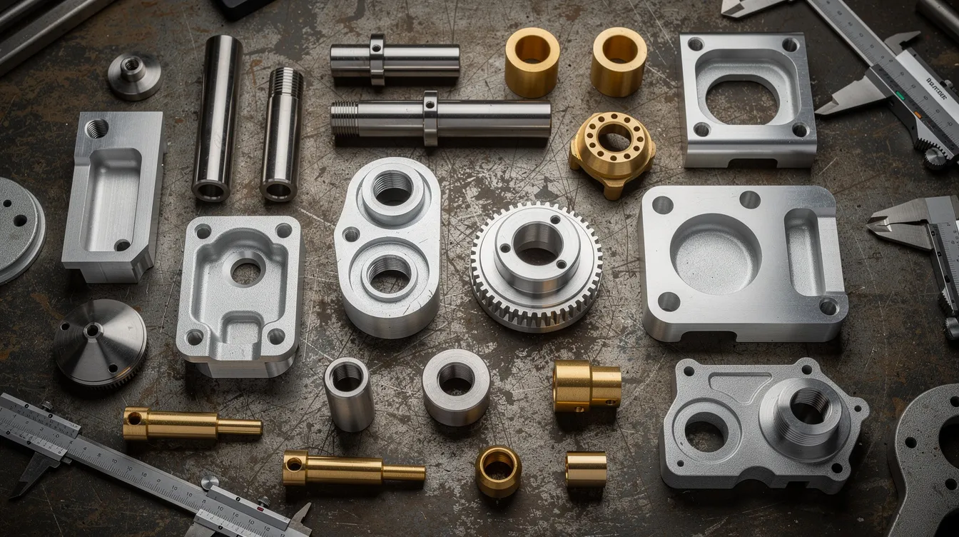
Studies consistently show that 80% of manufacturing costs are determined during the design stage. DFM guidelines simplify product production and reduce costs by catching expensive features before they reach the shop floor. DFM merges product design with production methods, and effective DFM reduces design rework and maintains quality. DFM can apply to designing parts or components of any complexity-from simple brackets to multi-feature housings.
Key geometric rules:
-
Internal radii: Sharp inside corners require tool diameters that match. A 6 mm end mill means a minimum 3 mm internal radius. Avoid features requiring extreme length-to-diameter ratio tools-they deflect and chatter.
-
Wall thickness: Minimum ~0.5–1 mm for aluminum; 2–3 mm for plastics to resist vibration and tool pressure. Thin walls risk warping.
-
Pocket and hole depth: Limit hole depth to 3–5× diameter. Deep pockets require longer tools that increase cost and deflection risk. Avoid unnecessary sharp edges in pocket floors.
-
Tolerancing: Call out tight tolerances only where function demands it-mating surfaces, bearing fits, sealing faces. Use general tolerances (ISO 2768) elsewhere. Every unnecessarily tight callout adds inspection time and scrap risk.
-
Datums and GD&T: Choose logical datum features. Specify flatness, perpendicularity, and true position via GD&T rather than stacking linear dimensions.
-
Surface finish: Avoid specifying fine finishes on hidden or non-functional areas.
Anebon frequently provides DFM feedback before production, especially for complex 5-axis components, helping overseas OEMs avoid redesign loops. Exploring Anebon’s guidance on small-batch CNC machining services offers additional practical tips.
Surface Finishes and Post-Processing for CNC Machined Parts
As-machined surfaces typically show tool marks, scalloping, or minor burrs. Post-processing addresses aesthetics, wear resistance, and corrosion protection.
Common finishes:
-
Bead blasting / shot peening: Produces a uniform matte finish; removes tool marks; improves fatigue life through work-hardening.
-
Brushing / polishing: Directional grain or high-luster mirror finish for visible surfaces.
-
Anodizing (Type II & Type III): For aluminum only. Type II provides decorative color and corrosion protection. Type III (hard anodizing) adds wear resistance at ~50 µm thickness. Note: thickness adds to dimensions-tight fits must account for it. Anebon’s anodizing finishing services detail available options, and their article on anodizing effects on surface quality covers dimensional impacts.
-
Powder coating / electrostatic paint: Durable color finish; requires proper surface prep.
-
Electroplating (Ni, Cr): Adds corrosion resistance and decorative quality.
-
Passivation: Chemical treatment for stainless steel to restore corrosion resistance after machining.
-
Black oxide: Thin cosmetic and corrosion-resistant layer for steel.
-
Laser engraving: Logos, serial numbers, traceability marks.
Use-case examples: Black hard-anodized 7075 drone frame components for scratch and wear resistance; bead-blasted and clear-anodized aluminum enclosures for consumer electronics. Anebon integrates machining and surface treatment through qualified partners, managing quality control across the full process chain.
Quality Assurance, Tolerances, and Certifications
Consistent quality is non-negotiable for overseas CNC machining projects, especially when precision parts go into safety-critical systems. CNC machining often requires in-process audits for quality control to catch deviations before they compound.
Metrology equipment in a modern shop:
-
CMMs (Coordinate Measuring Machines) are used to verify dimensions and tolerances in CNC parts
-
Height gauges, digital calipers, micrometers
-
Profilometers for surface roughness (Ra)
-
Thread gauges, optical comparators, hardness testers
Operators check part dimensions using various measuring tools at multiple stages. CNC machining can achieve tolerances of ±0.001 inches, with select critical dimensions reaching ±0.002 mm (approximately 0.0001 inches or 0.0025 mm) on features like sealing surfaces and bearing interfaces.
ISO certifications like ISO 9001:2015 and ISO 14001:2015 are important in CNC manufacturing. ISO 9001:2015 is a common quality management standard in CNC machining, and quality management systems ensure compliance with ISO standards. Anebon holds both ISO 9001:2015 and ISO 14001:2015 certifications, with documented QMS and environmental management. For aerospace or medical OEMs, typical quality documentation includes inspection reports, material certificates (CMTR), and first article inspection (FAI). Anebon’s approach to ISO-certified quality in metal manufacturing outlines their process in detail.
Roles in CNC Machining: CNC Machinists, CNC Machine Operators, and Engineers
Behind every precision part are people with specific metalworking skills and responsibilities.
CNC machinists are the technical backbone. They handle CNC programming, machine setup, tool selection, offset adjustments, and troubleshooting issues like chatter or thermal drift. They optimize feeds, speeds, and toolpaths to hit tolerances and surface finishes. CNC machinists often carry years of hands-on experience with CNC technology plus formal training.
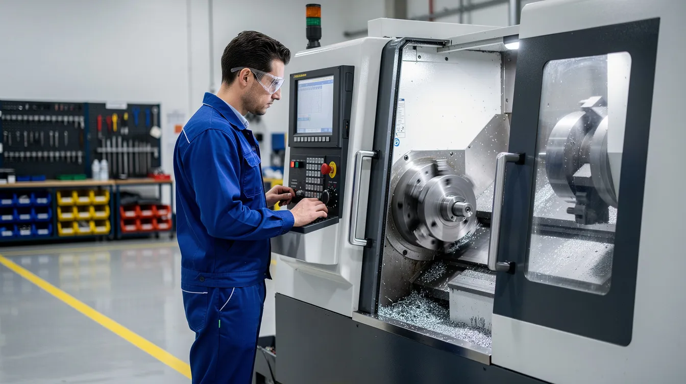
CNC machine operators (also called CNC operators) run pre-established programs, load and unload parts, perform basic inspection, swap cutting tools, and respond to alarms. Operators are responsible for loading, unloading, and inspecting parts throughout a production run. CNC machine operators must be proficient in technical drawings to interpret dimensions and GD&T callouts. CNC operators often require postsecondary training for proficiency-typically certificates or associate degrees in machining or manufacturing technology.
Design and manufacturing engineers work upstream and alongside the floor. Design engineers define dimensional tasks-tolerances, surfaces, materials. Manufacturing engineers handle DFM, fixture design, process flow, and cycle-time reduction. Collaboration between engineers and shop-floor staff is what makes complex parts come out right.
Anebon invests in ongoing operator training and cross-functional communication to keep overseas CNC machining reliable and repeatable for OEM clients.
Advantages, Limitations, and When CNC Beats Other Processes
CNC machining versus other manufacturing methods comes down to volume, geometry, and material requirements.
Advantages:
-
CNC machining achieves tolerances of ±0.001 inches or better, with exceptional repeatability in part production.
-
CNC machining reduces human error in production processes through automation and closed-loop control.
-
Strong, isotropic material properties because parts are cut from homogeneous stock-not layered or cast.
-
Wide material choice: metals, plastics, composites.
-
No dedicated tooling (molds, dies) needed, making it ideal for low to medium volume production.
-
Rapid prototyping and full-scale production are both achievable on the same CNC equipment-parts that once required complex machinery and weeks of setup can now move from CAD to first article in days.
-
CNC machining can produce complex shapes with high accuracy that would be impossible to replicate manually.
Limitations:
-
Per-part cost is higher than injection molding or die casting at very high volume production runs (once mold tooling cost is amortized).
-
Internal geometries (complex channels, enclosed cavities) are difficult or impossible-unlike additive methods or die casting, where molten metal fills intricate mold shapes.
-
Hard-to-machine materials like titanium and superalloys increase cycle time and tool wear.
-
Reliance on skilled CNC machinists and programmers.
Where CNC is the clear winner:
-
Aerospace brackets in batches of 50–500 units requiring tight tolerances and full traceability
-
Medical device housings needing ±0.01 mm fits and biocompatible materials
-
Robotics end-effectors iterated during R&D, where mass production tooling isn’t justified
-
Electronics enclosures in aluminum that need both structural integrity and aesthetic finish
Anebon frequently combines CNC machining with die casting and sheet metal fabrication, selecting the most cost-effective route as volumes and designs evolve. For custom CNC machining solutions at low-to-medium volumes, this hybrid approach often delivers the best balance of precision, speed, and cost.
Partnering with Anebon for Your Next CNC Machining Project
Anebon Metal Products Limited was founded in 2010 in Dongguan, Guangdong, China, and specializes in precision CNC machining, die casting, and sheet metal fabrication for overseas OEMs. The company holds ISO 9001:2015 and ISO 14001:2015 certifications and serves customers in aerospace, medical devices, automotive, electronics, and industrial robotics. With computer components and CNC technology advancing every year, Anebon keeps its fleet current to meet evolving demands.
Typical engagement flow:
-
NDA (if needed)
-
RFQ with CAD files and drawing package
-
DFM feedback from Anebon’s engineering team
-
Quotation with lead time
-
Sample run and first article inspection
-
Scale-up to production
Core capabilities: 3- through 5-axis CNC machines, rapid prototyping, tight tolerances down to approximately ±0.002 mm on critical features, wide materials and finishes, and ISO-certified quality systems. Application sectors include aerospace precision components, medical device parts, automotive sensor housings, and industrial robotics hardware.
Ready to start? Send your CAD files or contact Anebon’s engineering team to discuss manufacturability, costs, and lead times for your CNC machining project. Getting DFM feedback early is the fastest way to reduce cost and avoid surprises during production.