Essential CNC Part Guide: Choosing the Right Components for Success
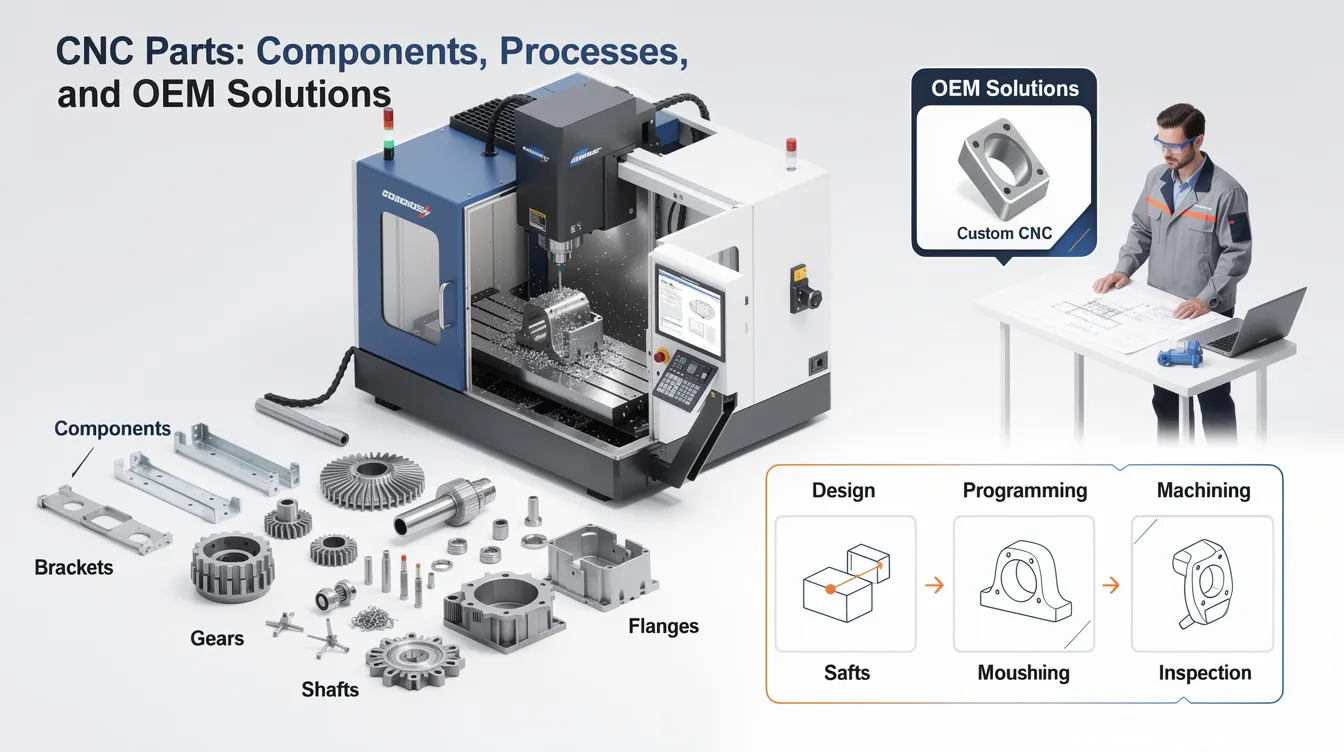
CNC Parts: Components, Processes, and OEM Solutions
Every precision product – from a surgical instrument to an electric vehicle drivetrain – depends on parts that meet exact specifications. In 2026, the ability to source reliable, repeatable cnc machine parts is what separates competitive OEMs from those struggling with quality escapes and delivery delays. This guide covers the full landscape: what a cnc part actually is, how the machining process works, which materials and tolerances matter, and how to order custom parts with confidence.
Quick Overview of CNC Parts and Our Services
A cnc part is any custom metal or plastic component produced on a computer numerical control machine – whether through cnc milling, cnc turning, 5-axis machining, or cnc routers. These parts are foundational across almost every major industry, including aerospace, automotive, medical devices, electronics, and industrial robotics.
Anebon Metal Products Limited is an ISO 9001:2015 and ISO 14001:2015 certified cnc machining services provider founded in 2010 in Dongguan, Guangdong, China. We serve overseas OEMs across Europe, North America, and Asia-Pacific with a full suite of precision manufacturing processes.
Core capabilities:
-
Cnc milling (3-axis through 5-axis machining centers)
-
Cnc turning (CNC lathes and Swiss-type lathes with live tooling)
-
5-axis cnc machining for complex geometries
-
Die casting and sheet metal fabrication
-
Rapid prototyping through full-scale production runs
-
Surface treatments: anodizing, electroplating, powder coating, bead blasting, and more
CNC machining offers high precision with tolerances of ±0.001 inches (down to ±0.002 mm on critical features), and we apply comprehensive quality control to every order. CNC machining also reduces labor costs by automating production processes, making it viable for both prototype and volume work.
Ready to get started? Send your CAD files to our engineering team for a fast, no-obligation quote on your next cnc parts project.
What Is a CNC Part?
A cnc part is any metal or plastic component manufactured via computer numerical control on a cnc machine – lathe, mill, machining center, or cnc router. Unlike manual machining, where an operator controls every machine movement by hand, the cnc machining process relies on programmed digital instructions to perform operations with tight tolerances and full repeatability.
Here is what separates cnc parts from conventionally machined parts in practical terms:
-
Automation: The entire process – from tool changes to feed rates – is controlled by g code, not hand wheels.
-
Repeatability: Part #1 and part #10,000 come off the machine within the same tolerance band.
-
Tighter tolerances: CNC machining produces parts with tolerances of ±0.001 inches, which is difficult to achieve consistently with manual methods.
-
Digital workflow: CNC machines operate based on designs created with CAD software, enabling direct translation from engineering intent to finished part.
CNC parts are suitable for a wide range of metals and plastics. In fact, cnc machining can create parts from over 50 different materials, giving engineers broad design flexibility. CNC technology is essential for creating prototypes and high-volume production runs alike.
Real-world examples from recent OEM projects:
-
Aluminum 7075-T6 drone frame brackets (2024, aerospace startup)
-
Stainless steel 316L medical device housings (2025, surgical equipment OEM)
-
Alloy steel 4140 gearbox shafts (2023, industrial automation company)
-
POM/Delrin robotics spacers and insulators (2026, collaborative robot manufacturer)
Cnc parts can range from a single prototype to tens of thousands of production parts for the same drawing – all produced with consistent performance and dimensional accuracy.
Key CNC Machine Parts (Components of a CNC Machine)
Understanding the main parts of a cnc machine helps engineers design better cnc parts. When you know what drives precision and rigidity inside the machine, you can make smarter decisions about tolerances, features, and material selection for your components.
Control System Components
-
Control panel: The operator interface where programs are loaded, offsets are entered, and machining operations are monitored in real time.
-
Machine control unit (MCU): The brain of the cnc machine. The machine control unit interprets digital instructions – typically g code – and converts them into coordinated machine movements across all axes. The CNC machine’s control unit interprets g code to execute commands for spindle speed, feed rate, tool changes, and axis positioning.
-
Input device: USB ports, Ethernet connections, or DNC interfaces used to transfer cad file data and programs from external computers to the controller.
-
Feedback system: Encoders and linear scales that continuously report the actual position of each axis back to the control system, enabling closed-loop correction and high precision.
Mechanical Components
-
Machine bed: The foundation of the machine tool. The bed supports core components like the worktable and spindle assembly, and its rigidity directly affects achievable dimensional accuracy.
-
Linear guideways: Hardened rail systems that provide precise linear motion for cnc machine components, ensuring smoother surfaces and consistent cuts.
-
Ball screws: These convert rotary motion from servo motors into linear motion, positioning the table and spindle with micron-level accuracy. Ball screws are a critical element of power transmission within the driving system.
-
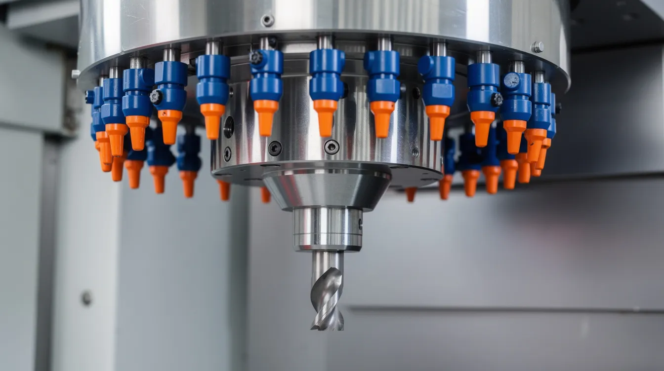
Spindle: The CNC spindle holds and drives the cutting tool during machining operations. Spindle speed, runout, and bearing quality all influence surface finish and tool life.
-
Tool magazine and automatic tool changer (ATC): Stores multiple tools and swaps them automatically mid-program, allowing the machine to perform operations like drilling, milling, and tapping without manual intervention.
Motion and Power Components
-
Servo systems: Precision motors that control axis movement. Servo systems receive commands from the MCU and work with the feedback system to achieve target positions accurately, forming the primary function of the driving system.
-
Coolant system: Delivers flood coolant or minimum quantity lubrication to manage heat and evacuate chips from the cutting zone, especially important for materials that generate high temperatures.
-
Lubrication system: Automatically distributes oil to guideways, ball screws, and bearings, reducing friction and wear for consistent performance over long production runs.
Safety and Usability
-
Safety interlocks and emergency stop: Prevent operation when doors are open and allow immediate shutdown.
-
Way covers and cable carriers: Protect precision surfaces from chips and coolant contamination.
-
Handwheel (MPG): Allows manual jog for setup, alignment, and troubleshooting.
All of these cnc machine parts work together as an integrated system. The control system sends commands, servo systems drive machine movements, the feedback system confirms position, and the mechanical structure provides the rigidity needed for precision machining – collectively delivering high quality parts run after run.
How CNC Machining Creates CNC Parts
The cnc machining process follows a defined sequence from digital design to inspected, finished component. Understanding each stage helps OEM engineers communicate requirements more effectively and avoid costly revisions.
Step 1: CAD Design
The process begins with cad modeling of the part. Engineers create 3D models and 2D drawings in software like SolidWorks, CATIA, or Fusion 360, defining dimensions, tolerances, critical surfaces, and material callouts. A well-prepared cad design with clear GD&T annotations speeds up everything downstream.
Step 2: CAM Programming
cam software converts the 3D model into toolpaths – the specific routes that each cutting tool will follow. During this step, programmers select machining operations (cnc milling, cnc turning, drilling, tapping) and generate g code. G-code is generated from CAD files for CNC machining, encoding every spindle speed, feed rate, and tool change into instructions the machine can execute.
Step 3: Machine Setup
The right cnc machine is selected based on part geometry and size – 3-axis mill, 5-axis machining center, Swiss lathe, or cnc routers for larger flat components. CNC machines can operate on multiple axes for complex shapes. Tools are loaded into the automatic tool changer, work offsets and tool length offsets are set, and a first piece is typically run for verification.
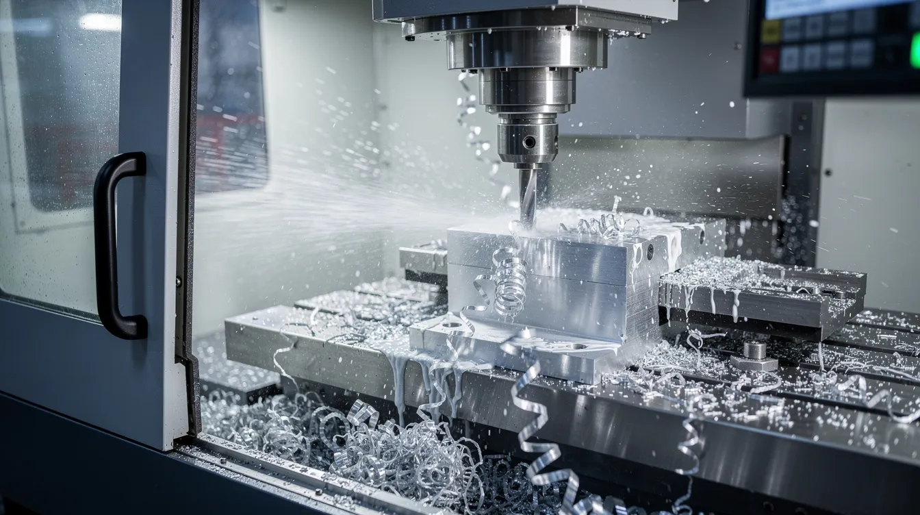
Step 4: Machining
During the actual subtractive manufacturing process, the machine tool removes material layer by layer. Spindle speeds, feed rates, and tool changes are all controlled automatically by the machine based on the programmed g code. Coolant is applied during machining to manage heat and debris – critical for maintaining dimensional accuracy and extending tool life, especially on materials with low thermal conductivity. This subtractive process generates metal parts with complex geometries directly from solid stock, minimizing material waste compared to many alternative manufacturing processes.
Step 5: Finishing Operations
After cutting, most cnc parts require secondary operations:
-
Deburring and edge breaking
-
Grinding or polishing for smoother surfaces
-
Anodizing (Type II or Type III) for aluminum
-
Electroplating (nickel, zinc, chrome)
-
Powder coating for corrosion protection and aesthetics
-
Bead blasting or brushing for uniform texture
Step 6: Inspection and Quality Control
The entire process concludes with comprehensive quality control. CMM checks verify critical dimensions, in-process gauging catches drift during long runs, and final visual inspection confirms surface finish and cosmetic requirements before packing and export. Documentation – inspection reports, material certificates, and first-article records – accompanies every shipment.
Main Types of CNC Parts by Process
Most cnc parts for OEMs are produced via cnc milling, cnc turning, or hybrid mill-turn machining operations. Each process suits different part geometries and production requirements.
CNC Milling Parts
CNC milling machines remove material using rotary cutters to produce prismatic components – housings, brackets, heat sinks, manifolds, and enclosures. CNC milling is used for complex geometries like helicopter rotor blade fittings, aerospace structural components, and intricate electronic housings. Machines range from 3-axis to 5-axis machining centers equipped with automatic tool changers that can hold 20–60+ tools.
CNC Turning Parts
CNC lathes produce precise cylindrical parts by rotating the workpiece against a stationary cutting tool. CNC turning is ideal for producing cylindrical parts like shafts, bushings, pins, fittings, and fasteners. Many modern lathes include live tooling for secondary milling, drilling, and tapping – creating cylindrical features along with cross-holes, flats, and keyways in a single setup. CNC Swiss lathes are designed for high-precision, small-diameter parts such as medical pins, watch components, and connector contacts.
CNC Routers
CNC routers carve and shape materials like wood, plastics, composites, and soft metals. They excel at larger flat parts – electronics enclosures, display panels, signage hardware – where material removal is extensive but tolerances are moderate compared to metalworking mills.
Other CNC Processes
Beyond the core milling and turning categories, several specialized cnc operations serve specific needs:
-
CNC EDM machines use electrical sparks to remove material from conductive workpieces, ideal for hardened tool steel and intricate mold cavities.
-
CNC laser cutting machines use lasers to cut and engrave materials with minimal kerf and no contact force.
-
Waterjet machines cut heat-sensitive or reflective materials without thermal distortion.
CNC machines can produce complex geometries efficiently, and combining multiple process types on a single project is common for complex parts.
Real-World Application Examples
|
Year |
Part |
Process |
Material |
|---|---|---|---|
|
2024 |
EV motor housing |
5-axis milling |
Aluminum 6061-T6 |
|
2025 |
Surgical instrument handle |
CNC turning + milling |
Stainless steel 316L |
|
2023 |
Industrial robot joint |
Alloy steel 4340 |
|
|
2026 |
RF antenna bracket |
CNC milling |
Brass C360 |
Custom surgical instruments and implants are produced using CNC parts in the medical industry, where biocompatibility, traceability, and tight tolerances are non-negotiable.
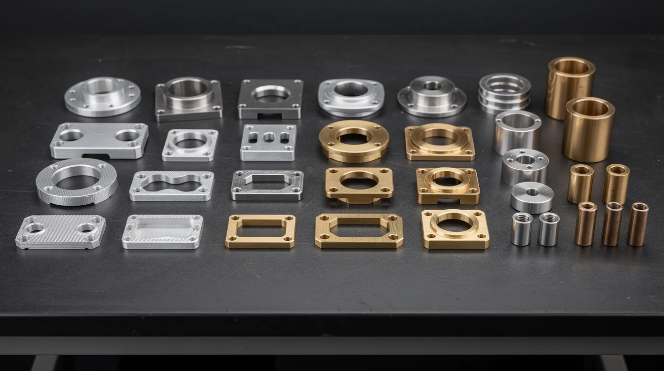
Materials Used for CNC Parts
Material selection is one of the most consequential decisions in any cnc machining project. Anebon machines both metals and engineering plastics, and the right choice depends on mechanical requirements, environment, regulatory standards, and budget.
Aluminum Alloys
Aluminum alloys like 6061 are popular for CNC machining because of their excellent machinability, low weight, and corrosion resistance. 6061-T6 delivers about 310 MPa (45 ksi) tensile strength with roughly 90% machinability relative to free-machining baselines. 7075-T6 offers higher strength for aerospace structural parts. These alloys are ideal for drone frames, consumer electronics housings, and custom irregular aluminum parts.
Stainless Steel
Stainless steel grades like 304 offer excellent corrosion resistance, making them standard for medical devices, food-processing equipment, and marine hardware. 316L adds molybdenum for improved pitting resistance. 17-4 PH provides high strength after heat treatment. Stainless steels tend to work-harden, requiring slower feeds and robust tooling, but they deliver good mechanical properties for demanding environments.
Steel Alloys
Alloy steel grades like 4140 and 4340 provide tensile strength in the 650–750 MPa range. These steel alloy options are selected when strength, wear resistance, and fatigue life are critical – gearbox shafts, power transmission components, and fixture tooling. Carbon steel and mild steel grades like 1018 offer a lower-cost option for structural or non-corrosion-critical parts. Tooling durability affects the choice of materials for CNC tooling, and harder steels demand carbide or coated inserts to maintain production efficiency.
Brass and Copper
Brass alloys like C360 are known for excellent machinability – they cut quickly, produce clean chips, and hold tight tolerances with minimal tool wear. Common applications include valves, connectors, and decorative hardware. Copper is highly conductive and used for electrical applications such as bus bars, heat sinks, and RF components, where electrical conductivity matters more than strength.
Titanium
Titanium is favored for its high strength-to-weight ratio. Ti-6Al-4V (Grade 5) is the workhorse alloy for aerospace and medical implant cnc parts. However, titanium costs 5–10× more than common aluminum alloys, has roughly 20–30% machinability relative to free-cutting steel, and exhibits low thermal conductivity – meaning heat concentrates at the cutting tool tip. Cutting speeds for Ti-6Al-4V typically run 18–46 m/min with high-pressure coolant. Despite these challenges, titanium CNC machining remains indispensable for parts requiring heat resistance and excellent corrosion resistance in aggressive environments.
Engineering Plastics
|
Plastic |
Key Properties |
Typical Applications |
|---|---|---|
|
POM (Delrin) |
Low friction properties, dimensional stability |
Gears, bearings, guides |
|
Nylon (PA) |
Good mechanical properties, chemical resistance |
Bushings, housings, spacers |
|
PEEK |
Heat resistance up to 260°C, high strength |
Aerospace seals, medical implants |
|
ABS |
Easy to machine, good impact resistance |
Prototypes, consumer products |
|
Polycarbonate |
High impact strength, optical clarity |
Lenses, guards, enclosures |
These plastics machine quickly but are sensitive to thermal deformation at high temperatures, and tolerances generally loosen compared to metal parts.
Critical Features of High-Quality CNC Parts
When engineers specify cnc machining services for production parts, quality criteria go far beyond “does it look right.” OEMs in aerospace, automotive, and medical sectors demand quantifiable, documented evidence that every cnc part meets specification.
Tolerances and Dimensional Accuracy
Dimensional tolerance impacts the cnc machining process significantly. Typical ranges for CNC milled metal parts:
-
Standard linear dimensions: ±0.05 mm
-
High-precision dimensions: ±0.02 mm with stable setups and high-rigidity machines
-
Reamed/bored holes: ±0.025 mm standard, down to ±0.01 mm with grinding
-
Anebon critical feature capability: ±0.002 mm on specific dimensions
CNC machining produces parts with tolerances of ±0.001 inches, but achieving this consistently requires proper machine calibration, thermal stability, rigid fixturing, and controlled tool wear – not just a capable machine.
Surface Finish
Surface finish targets vary by application. Standard as-machined surfaces fall in the Ra 0.8–3.2 µm range. Post-processing like grinding or polishing can push finishes to Ra 0.1 µm for optical or sealing surfaces, producing smoother surfaces that improve part function and appearance.
Geometric Accuracy
True position, concentricity, perpendicularity, and flatness are controlled through machine rigidity, fixturing strategy, and thermal management. Machine rigidity influences cutting depth and quality in CNC machining – a more rigid machine bed and structure produce tighter geometric tolerances across the part.
Batch Repeatability
For OEM clients ordering thousands of identical custom components each year, consistent performance across batches is essential. Statistical process control (SPC) with Cpk ≥ 1.67 on critical dimensions is now expected by demanding customers. The initial investment for CNC machines is typically high, but this investment pays for itself in repeatable, automated production that manual machining cannot match.
Design Limitations
CNC machining can struggle with interlocking and hollowed structures – internal undercuts, fully enclosed cavities, and features that cannot be reached by standard cutting tools. Recognizing these limitations early prevents costly redesigns.
Traceability
For regulated industries, lot numbers, inspection reports, and material certificates (ASTM, EN, or GB standards) must accompany every shipment. Full traceability from raw stock to finished cnc part is non-negotiable in aerospace (AS9100) and medical (ISO 13485) supply chains.
Design Tips for Better CNC Parts
Design-for-manufacturing (DFM) is where cost optimization and machinability improvements happen – long before the cutting tool touches metal. A few practical decisions at the cad design stage can significantly reduce cycle time, tooling cost, and scrap rate.
-
Tighten tolerances selectively. Specify tight tolerances only on mating surfaces, bearing bores, and functional interfaces. Every feature held to ±0.01 mm instead of ±0.05 mm increases machining time and inspection cost. Ask whether the function truly demands it.
-
Simplify geometries where possible. Avoid deep, narrow pockets with high depth-to-width ratios (greater than 4:1), extremely thin walls (under 0.5 mm for metals), and unreachable internal undercuts. These features raise cycle time, require special tooling, and increase the risk of scrapped parts.
-
Standardize hole sizes. Using common drill and tap sizes reduces the need for special tooling and allows the automatic tool changer to work with standard magazines.
-
Add internal radii. Fillets compatible with standard end mill sizes (e.g., R1.5 for a 3 mm end mill) reduce tool stress, improve chip evacuation, and extend tool life.
-
Design for fixturing. Include reference surfaces or clamping features that allow stable workholding – this directly improves dimensional accuracy and reduces setup time.
-
Leverage rapid prototyping first. Rapid prototyping allows for testing new designs before mass production. Running 5–10 prototype parts through actual cnc operations reveals machining challenges and tolerance stack-ups before you commit to production tooling.
Get DFM feedback from Anebon’s engineers before locking designs. For 2024–2026 development cycles, early collaboration on material selection, tolerance budgets, and process routing can shave 15–30% off unit costs.
Comprehensive Quality Control for CNC Parts
Aerospace, medical, and automotive OEMs do not just buy metal parts – they buy documented, traceable, statistically verified components. CNC parts are heavily utilized in the aerospace and automotive industries, where a single out-of-spec dimension can ground aircraft or trigger recalls. Anebon’s quality system is built to meet these expectations.
Certifications
Anebon holds ISO 9001:2015 (quality management) and ISO 14001:2015 (environmental management) certifications. These structure every element of process control – from incoming material inspection through final packing. For customers in regulated sectors, we support documentation aligned with AS9100D (aerospace), IATF 16949 (automotive), and ISO 13485 (medical) requirements.
Inspection Equipment
-
Coordinate measuring machines (CMM) for 3D dimensional verification
-
Height gauges and pin gauges for quick in-process checks
-
Thread gauges (go/no-go) for threaded features
-
Optical projectors for profile verification
-
Surface roughness testers for surface finish validation
-
Hardness testers for heat-treated or case-hardened cnc parts
In-Process and Final Inspection
Our quality control checklist covers three stages:
-
First-article inspection: The first piece off the machine is fully measured against the drawing before production continues.
-
Patrol inspection: During long runs, operators perform periodic gauging at defined intervals to catch drift before it produces scrap.
-
Final inspection: 100% visual inspection plus dimensional checks on critical features before shipment.
Documentation
Depending on customer requirements, we provide inspection reports, PPAP or FAIR (First Article Inspection Report), material mill certificates, and SPC data. Every inspection instrument is calibrated and traceable to national standards, maintaining high quality standards across all cnc operations.
Facility Conditions
Our Dongguan facility maintains stable temperature zones in precision machining areas, controlled humidity, and clean workstations – environmental factors that directly affect consistent performance and dimensional accuracy on high precision machining parts.
Why OEMs Choose Anebon for CNC Parts
CNC machining is widely used in aerospace, medical, and automotive industries – and OEMs in these sectors need more than a machine shop. They need a manufacturing partner who delivers high quality parts with documentation, engineering support, and reliable logistics. Here is why OEM teams choose Anebon:
-
15+ years of OEM experience: Since 2010, we have served overseas clients across Europe, North America, and Asia-Pacific with production parts and custom components.
-
One-stop capabilities: Cnc turning, cnc milling, 5-axis machining, die casting, and sheet metal fabrication under one roof – reducing supply chain complexity and lead time.
-
Fast prototyping: Rapid prototyping turnaround often within 5–7 working days, with scalable capacity for volume production orders.
-
Engineering support: DFM reviews, alternative material recommendations, and cost-optimization suggestions during the RFQ stage – before you spend a cent on tooling.
-
Certified quality: ISO 9001:2015 and ISO 14001:2015 certifications with comprehensive quality control applied to every project.
-
Export logistics: Stable shipping from Guangdong, handling Incoterms like EXW, FOB Shenzhen, and DAP for 2024–2026 projects.
Ordering Custom CNC Parts from Anebon
Getting custom cnc parts from Anebon is a straightforward process designed around production efficiency and clear communication.
-
Submit your RFQ: Send 3D CAD files (STEP, IGES, or equivalent cad file formats) plus 2D drawings with tolerances, material, quantity, and surface finish requirements. The more detail you include, the more accurate and faster the quote.
-
Receive your quote: Typical turnaround is 24–48 hours on working days. Our engineers may suggest alternative materials, tolerance adjustments, or process changes to reduce cost or lead time without sacrificing function.
-
Production flow after PO: Process planning → CAM programming → machine setup → machining → finishing (anodizing, plating, powder coating, etc.) → comprehensive quality control → export packing. You receive inspection reports and shipping documents with every order.
-
Shipping options: Air express for prototypes and urgent small batches; air freight or sea freight for larger, recurring cnc parts orders.
Whether you are sourcing a single prototype or scaling to thousands of production units, Anebon’s team is ready to support your project from the first cad design review to final delivery.
Contact Anebon today to request a quote on your next cnc parts project. Send your drawings, tell us the quantity and timeline, and our engineers will get back to you within 48 hours with a detailed proposal.
Conclusion
CNC parts produced via cnc machining, cnc milling, and cnc turning are essential for modern aerospace, medical, automotive, and electronics products. From aluminum drone brackets to alloy steel drivetrain shafts and titanium implant components, the right machine tool, material, and quality system determine whether your product succeeds or fails in the field.
Anebon Metal Products Limited brings wide material capabilities – aluminum, stainless steel, alloy steel, titanium, brass, copper, and engineering plastics – together with tight tolerances, automatic tool changer–equipped machines, and comprehensive quality control under ISO-certified processes. As OEM requirements grow more demanding in 2026 and beyond, partnering with a supplier that combines precision machining expertise, engineering support, and scalable capacity is not optional – it is how you stay competitive.