CNC Machining vs Die Casting Prototyping: Differences, Advantages, Disadvantages
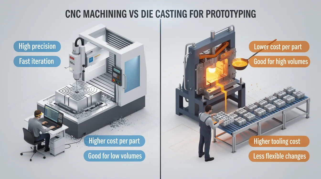
CNC Machining vs Die Casting for Prototyping: Key Differences, Advantages & Disadvantages
Choosing between cnc machining vs die casting for prototyping is one of the most consequential decisions an OEM design team will make. The wrong call burns budget, delays timelines, and produces parts that fail to validate your design. This guide breaks down the key differences, advantages, and disadvantages of both manufacturing methods so you can pick the right process for your current stage.
1. Fast Answer: When to Prototype with CNC Machining vs Die Casting
If you are building 1–500 prototypes and the design is still evolving, choose cnc machining. CNC machining is preferred for low-volume runs and prototypes because there is no tooling investment, lead times run 5–10 working days, and changing the cad model costs nothing beyond reprogramming. CNC machining is more cost-effective for production runs under 1,000 parts in virtually every scenario.
Die casting only makes sense for late-stage validation when the design is frozen, production volume is forecast above roughly 5,000 pieces per year, and the upfront tooling cost of $15,000–$50,000 or more can be amortized across enough units. Die casting is more cost-effective for high volume production once those conditions are met.
At Anebon Metal Products Limited, we routinely start with CNC prototypes in aluminum 6061, 7075, stainless steel, or engineering plastics, then transition customers to aluminum or zinc die casting plus secondary cnc machining when demand stabilizes.
Choose CNC machining when:
-
Order quantity is low (1–500 pieces) or the design is still changing
-
Extremely tight tolerances (±0.01 mm or better) are needed
-
You require a broad range of materials, including tough materials like titanium or stainless steel
-
Fast turnaround for iteration is a priority
-
Part geometry features sharp edges, deep pockets, or sharp internal corners
Choose die casting when:
-
Design is locked with minimal modifications expected
-
Annual volume forecast exceeds 1,000–5,000 units
-
Thin walls, integrated ribs, bosses, and complex shapes are central to the design
-
Lower per-part cost at scale and high repeatability are priorities
-
Prototypes need to replicate final production surface finish, texture, and part geometry
2. Overview: Manufacturing Techniques in Prototyping
CNC machining is a subtractive manufacturing process where computer controlled tools-mills, lathes, and 5-axis centers-cut metal parts and plastic components from a solid block of billet or plate. Die casting is a casting process that injects molten metal under high pressure into a hardened steel die cavity, producing near-net-shape parts after solidification.
In prototyping, these manufacturing techniques serve different roles. CNC machining provides rapid, flexible development and quick design iteration. Die casting serves near-production validation of geometry and manufacturing feasibility. Both can achieve high dimensional accuracy, but the same precision is more economical and repeatable with CNC on small batches than with a dedicated die casting process.
-
CNC machining workflow: CAD model → CAM toolpath generation → material removal from billet → deburring and finishing → optional surface treatment
-
Die casting workflow: die design (parting line, gating) → mold creation and tryout → molten metal injection → cooling and ejection → trimming → possible secondary machining → surface finishing → inspection
3. What Is CNC Machining for Prototyping?
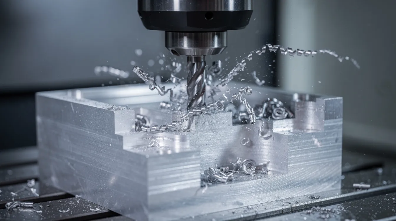
CNC machining is a programmable, subtractive process ideal for one-off and low-volume prototypes-typically 1–200 parts-in metals and plastics. The cnc machining process uses removing material from stock to achieve the desired shape with high precision. CNC machining is ideal for prototypes and small batches because it requires no dedicated tooling, and CNC machining allows for quick design changes without extensive setup.
At Anebon, typical prototype machine tools include 3-axis and 5-axis CNC milling centers, CNC turning centers, and mill-turn machines. These are well-suited for complex part geometry and tight tolerances down to ±0.002 mm in controlled setups. CNC machining offers high precision and tight tolerances across every run.
-
Workflow: Start with a computer aided design file, generate CAM toolpaths, machine from billet, deburr, then optionally anodize, plate, bead-blast, or paint
-
Materials: CNC machining supports a wide range of materials including metals and plastics-aluminum 6061/7075, stainless 304/316/17-4PH, titanium, brass, copper, and engineering plastics like PEEK, PC, ABS, and PA (nylon)
-
No tooling cost: CNC machining has no tooling investment, allowing quick part production and eliminating the cost barrier of mold creation
-
CNC machining provides excellent surface finishes directly from the machine, with optional post-processing for aesthetic or functional requirements
-
Speed: CNC machining is faster for small batches or prototypes, with lead times often under two weeks for 5–10 units
4. What Is Die Casting for Prototyping?
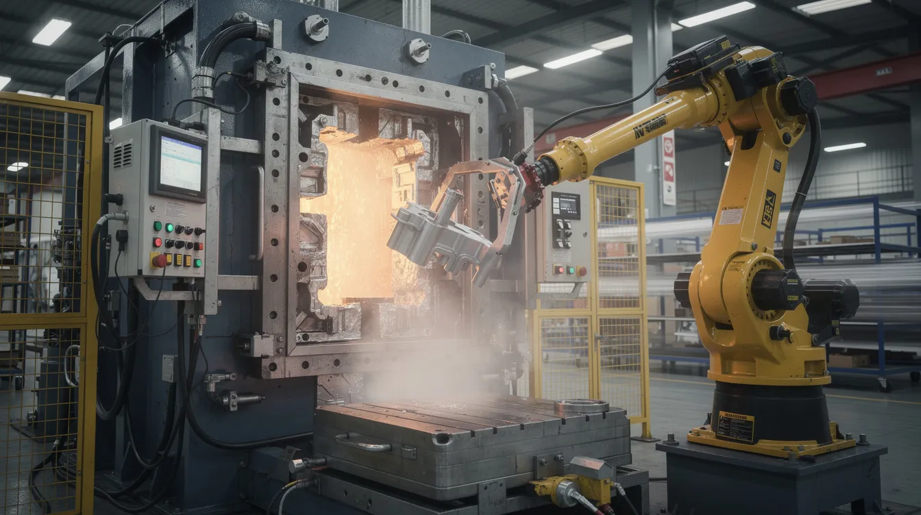
Die casting is a high-pressure casting process that pushes molten non-ferrous metals into precision steel dies. Die casting uses molten metal injected into molds to form complex shapes in a single shot. Common die casting materials include aluminum, zinc, and magnesium alloys-specifically aluminum A380/ADC12, A360, zinc Zamak 3/5, and magnesium AZ91D. Die casting typically requires materials with lower melting points and good fluidity.
Standard die cast tooling is optimized for tens of thousands to hundreds of thousands of shots, which is why traditional aluminum die casting is rarely used for very early prototypes. Die casting molds require significant investment and are expensive to modify. Die casting requires significant upfront investment for mold creation, making it impractical for just 10–50 parts.
For pre-production validation and pilot runs (1,000–20,000 parts of an automotive housing or electronics enclosure), teams may use production-intent dies or “soft” dies in aluminum or P20 steel.
-
Process sequence: die design and CNC machining of the mold cavity → die assembly and tryout → molten metal injection → cooling → part ejection → trimming flash and runners → possible secondary cnc machining on critical features
-
Die casting produces parts with complex geometries and internal features including thin walls, ribs, bosses, and complex internal geometries formed by cores and slides
-
High initial costs and long lead times characterize die casting due to tooling-typically 6–12 weeks for mold build alone
5. Key Process Differences: Subtractive vs Casting
The fundamental distinction between machining and die casting lies in how material becomes a finished part. CNC machining is a subtractive manufacturing process: computer controlled tools cut away material from a solid block until the desired shape emerges. Die casting works in the opposite direction-it is a process that injects molten metal into a mold, filling a die cavity where the cast metal solidifies into near-net shape. This core difference drives every downstream trade-off in prototyping.
Among modern manufacturing and casting methods-including sand casting, investment casting, and injection molding-die casting stands out for its production speed on non ferrous metals. But CNC machining remains the default for prototyping where flexibility matters more than cycle time.
-
How material is shaped: CNC achieves the desired shape through material removal; die casting works by flowing and solidifying cast metal in a mold cavity
-
Part geometry impact: CNC is limited by tool access, cutter reach, and minimum diameter; die casting is constrained by parting line placement, draft angles (1–3°), and flow path design
-
Internal features: CNC excels at machined channels, precision bores, and sealing faces; die casting enables complex internal geometries through cores and slides-geometries that CNC may not access at all
-
Cycle time: CNC prototypes take minutes to hours per piece depending on complexity; die casting cycle times are typically 30–90 seconds per part once tooling exists, but that tooling takes weeks to build
-
Material scope: die casting is limited to non-ferrous metals like aluminum, zinc, and magnesium alloys with good fluidity; CNC handles ferrous metals, non ferrous metals, and plastics alike
6. Prototype Precision, Tolerances & Surface Finish
Dimensional accuracy and surface finish determine whether a prototype can validate real-world function-think fit checks at mating interfaces, sealing surfaces, bearing seats, and optical alignment in the electronics industries.
-
CNC tolerances: CNC machining typically achieves tolerances of ±0.01 mm on standard features. Standard CNC machining tolerances are ±0.025 mm for general dimensions, CNC machining can achieve tolerances down to ±0.005 mm with moderate process control, and CNC machining achieves tolerances as tight as ±0.002 mm under optimized setups. At Anebon, we hold ±0.002 mm on critical features like bearing seats and sealing faces.
-
Die casting tolerances: die casting typically holds tolerances of ±0.1 mm per 25 mm of feature length for aluminum castings. Zinc tends to perform better. Die casting tolerances can be tighter with added process control, but this increases cost and may require secondary machining of critical surfaces.
-
Surface finish: CNC machining finishes can easily reach Ra 0.8–1.6 µm on functional surfaces; standard machined finishes sit around Ra 3.2 µm. As-cast die surfaces usually range Ra 1.6–6.3 µm and may show parting lines and ejector marks. Selecting the right surface roughness is critical for functional prototypes.
-
Hybrid approach: For many programs, we die cast bulk geometry, then CNC machine sealing faces, bores, and threads to CNC-level precision. This “die cast + CNC secondary” approach is common for EV motor housings and drone gimbal brackets where both cost and precision matter.
7. Part Geometry & Design Constraints in Prototyping
Part geometry is one of the most important factors when choosing between CNC and die casting for prototypes. Some features are trivial in one process and impossible in the other.
-
CNC machining: great for deep pockets, sharp edges, sharp internal corners, and complex 3D surfaces on 5-axis machines. However, tool reach and minimum cutter diameter limit access. Very thin walls (<0.5–1.0 mm in aluminum) are difficult due to vibration and deflection. CNC machining can handle high-strength materials like titanium and stainless steel for demanding applications like turbine blades or aerospace brackets.
-
Die casting: excels at thin walls (down to ~1.0 mm in aluminum, ~0.5 mm in zinc), integrated ribs, bosses, and complex shapes in a single shot. Requires draft angles (typically 1–3°), uniform wall thickness, and careful gating to avoid porosity. Flow simulation helps predict defects before production begins.
-
Internal geometry: fully enclosed cavities and undercuts are achievable with die cast cores and slides, creating complex molds that form features CNC cannot reach. CNC may require a multi step process involving EDM or multiple setups.
-
Example: Consider a 150 × 100 × 30 mm aluminum electronics enclosure. Early in development, 3–10 units are CNC machined to test fit and assembly. Before building die casting tooling, the design is adjusted: side walls receive 1–2° draft, wall thickness is made uniform, ribs and bosses are added for stiffness, and parting lines are defined. Without these changes, the casting process will produce defective parts.
8. Material Choices, Mechanical Properties & Material Waste
For prototypes, material selection and material waste both affect cost, lead time, and how well the prototype represents final performance.
-
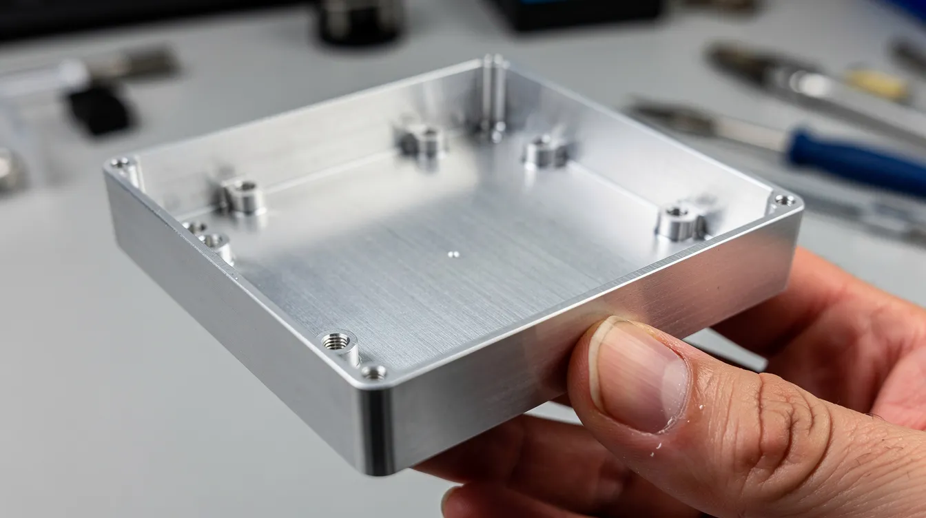
CNC materials: CNC machining works with hundreds of materials-aluminum 6061/7075, stainless steels (304, 316, 17-4PH), carbon steel, titanium, brass, copper, and plastics (ABS, PC, POM, PEEK). Prototypes can exactly match or exceed production-grade material strength. Wrought aluminum 6061-T6, for instance, delivers ~310 MPa tensile strength with predictable grain structure. Heat treatment options are available for most metals.
-
Die casting materials: limited to non-ferrous alloys-aluminum A380/ADC12, A360, A413, zinc Zamak 3/5, and magnesium AZ91D. You cannot die cast stainless steels or high-temperature alloys. Die casting typically requires materials with lower melting points and good fluidity.
-
Mechanical properties: cnc machined parts from wrought stock generally have higher strength, better fatigue resistance, and superior ductility compared to equivalent die cast parts. Die cast components may contain porosity from gas entrapment or shrinkage, reducing effective fatigue life. The mechanical properties of wrought versus cast versions of the same alloy can differ significantly.
-
Material waste: CNC machining generates 50–80% material waste during production, though chips are recyclable. Die casting produces less material waste than CNC machining since runners, gates, and sprues are re-melted. Understanding CNC machining cost drivers helps teams optimize their material choices.
-
Sustainability: moving from a machined-only prototype to a die cast design once geometry stabilizes reduces waste and energy per part at scale.
9. Production Volume, Cost Structure & Lead Time for Prototypes
Production volume-from one prototype to tens of thousands of units-is the single biggest driver of the economic choice between machining vs die casting.
-
CNC prototypes: no tooling cost. Cost scales nearly linearly with quantity. CNC machining typically has a lower upfront cost than die casting and remains economical for 1–500 units, often up to 1,000–2,000 parts depending on size and complexity. CNC machining can take months for large production runs of thousands of complex parts, making it impractical at scale.
-
Die casting prototypes: require upfront tooling investment ranging from roughly $8,000–$30,000 for a relatively simple single-cavity aluminum die, with 6–12 weeks to build. Die casting typically has lower per-part costs at high volumes-often dropping below a few dollars per piece. Die casting is cost-effective for production runs over 10,000 parts, and die casting is faster for producing thousands of units per day once tooling exists.
-
Break-even: for a mid-size aluminum enclosure, the crossover where casting becomes cheaper than CNC commonly occurs between 500–5,000 pieces, depending on tolerance, surface requirements, and whether secondary cnc machining is needed.
-
Lead time: CNC can ship first metal parts in 5–10 working days from finalized CAD. Die casting tooling plus first articles typically takes 6–10 weeks.
-
Typical OEM approach: many OEM customers validate early designs with 5–20 CNC prototypes, run a small pilot of 50–200 machined parts, then move to die cast production once demand and design are both stable. Die casting experts at Anebon guide this transition.
10. Advantages & Disadvantages of CNC Machining for Prototyping
Here is a quick-scan pros and cons breakdown for cnc machining in prototyping.
Pros:
-
Very high precision and repeatability on small batches-CNC machining achieves tolerances as tight as ±0.002 mm on critical features
-
Almost no restrictions on design changes; update the cad model and re-cut
-
Works with metals and plastics across hundreds of alloy and polymer grades
-
No die cost or mold creation required; the cnc machining process starts from a digital file
-
Supports complex 5-axis surfacing for complex parts like aerospace brackets, medical device housings, and robotics end-effectors
-
Shorter initial lead times (often under 2 weeks) and predictable per-part pricing
-
Excellent surface finish achievable directly from the CNC machine, with optional bead blasting, anodizing, or painting
Cons:
-
Material waste is high-CNC machining generates 50-80% material waste from removing material off the billet
-
Per-part cost remains relatively high as production volume grows beyond several hundred pieces
-
Machining time grows rapidly with complex 3D surfaces, deep cavities, or intricate internal features
-
Some geometries-sealed cavities, deep internal undercuts-are difficult or impossible
-
CNC prototypes may not reveal casting-specific defects (porosity, sink marks, flow lines) that will appear in a die cast part, so they don’t fully validate the die casting process
In industries like aerospace (structural brackets), medical devices (surgical instrument housings), and robotics (end-effectors), CNC machining is often kept as the final production method even beyond prototyping because volumes remain low and tolerance demands remain extreme.
11. Advantages & Disadvantages of Die Casting for Prototyping
Die casting is usually chosen not for first prototypes but for late-stage validation and production ramp-up when annual volumes justify tooling. Die casting is suited for high volume production after design finalization.
Pros:
-
Simulates mass production conditions: fill behavior, shrinkage, production speed, and typical die cast surface quality
-
Minimal material waste per part compared to CNC; very competitive unit cost at high volumes
-
Creates thin-walled, complex geometries in one shot-can die cast parts that would otherwise require multiple machined and assembled components
-
Many die cast parts achieve good as-cast surface finish suitable for powder coating, painting, or anodizing
-
High repeatability across tens of thousands of cast parts; die casting produces consistent results shot after shot
Cons:
-
High upfront tooling cost ($15,000–$80,000+) and long lead time (6–12 weeks for mold build)
-
Design changes after tooling require costly die modification or new inserts
-
Limited to specific alloys-no common stainless steels or high-temperature ferrous metals
-
Porosity and trapped gas can reduce strength and complicate pressure-tight or weldable designs
-
Small dimensional shifts due to tooling wear over long runs; minimizing shrinkage defects requires careful process control
Some OEMs bridge from CNC prototypes to full-scale casting by using temporary prototype dies-single-cavity P20 steel tools with shorter shot life-before investing in hardened H13 multi-cavity dies. This approach is common for automotive gearbox housings and LED lighting enclosures where the die casting process must be validated before committing to expensive production tooling.
12. Practical Prototyping Strategy: CNC First, Then Die Cast + CNC Secondary
Anebon’s recommended strategy for overseas OEMs: validate design with cnc machined parts first, then transition to die cast production using the same cad model optimized for the casting process, with critical features finished on CNC machines. This multi step process balances speed, cost, and production fidelity.
-
Step 1 – Concept & Early Validation: machine 3–10 prototypes in aluminum 6061-T6 or equivalent; test form, fit, and function; revise CAD as needed within days
-
Step 2 – Engineering Validation Test: produce 20–100 CNC-machined parts, possibly with different materials or coatings, to validate performance and assembly in pilot builds
-
Step 3 – DFM for Die Casting: collaborate with Anebon engineers to add draft, adjust wall thickness, define parting lines, add ribs, and minimize material waste in the future die cast part
-
Step 4 – Tooling & Pre-Production: build die casting tooling in Dongguan; run first article inspection; then apply secondary cnc machining to precision surfaces, threads, and tight-tolerance features on the die cast parts
-
Step 5 – Ramp to Volume: shift most volume to die casting for mass production cost efficiency while retaining CNC capacity for engineering changes, spare metal parts, and low-volume variants
Anebon holds ISO 9001:2015 for quality management and ISO 14001:2015 for environmental management. We provide CMM inspection and 2D/3D measurement reports on both CNC machined and die cast prototypes, ensuring dimensional accuracy at every stage.
13. How Anebon Helps You Choose: DFM, Quotes & Example Applications
Anebon Metal Products Limited, founded in 2010 in Dongguan, China, is a one-stop partner for CNC machining, die casting, and sheet metal fabrication-from rapid prototyping through full-scale OEM production.
-
DFM feedback: we review your designs for both cnc machined parts and die cast configurations, highlighting differences in draft, wall thickness, achievable tolerances, and cost impact before you commit
-
Industries served: automotive EV battery and motor housings, consumer electronics enclosures, medical equipment frames, robotics gearboxes, industrial machinery brackets-anywhere that cnc machining and die casting intersect
-
How to engage: send 3D CAD (STEP, IGES, native formats) and 2D drawings; receive comparative quotes for CNC machining casting vs pure die casting vs a hybrid route, complete with lead time estimates for each
-
Capacity: from a single prototype on a high precision 5-axis machine to multi-cavity die casting with secondary machining, surface finishing, heat treatment, and assembly
Ready to move forward? Send your designs to Anebon for a free manufacturability review. We will recommend whether to choose cnc machining, die casting, or a hybrid route based on your current prototyping stage, target production volume, and performance requirements. Request a quote today and let our die casting experts and CNC engineers guide your project from first prototype to high volumes.